Table of Contents
Advertisement
Installation and Operating Data
FOR YOUR SAFETY - This product must be installed and serviced by authorized
personnel, qualified in pool/spa heater installation. Improper installation and/or operation
can create carbon monoxide gas and flue gases which can cause serious injury, property
damage, or death. Improper installation and/or operation will void the warranty.
Installation and
Operation Manual
XL-3™
Oil-Fired Pool
and Spa Heater
Model DP3000
No.2 Fuel Oil Only
If these instructions are not followed exactly, a fire or explosion may result,
causing property damage, personal injury, or death.
Do not store or use gasoline or other flammable vapors and liquids in the
vicinity of this or any other appliance.
• Do not try to light any appliance.
• Do not touch any electrical switch; do not use any phone in your building.
• Immediately call your fuel supplier from a neighbor's phone. Follow the fuel
supplier's instructions.
• If you cannot reach your fuel supplier, call the fire department.
Installation and service must be performed by a qualified installer, service
agency or the fuel supplier.
WARNING
WHAT TO DO IF YOU SMELL FUEL
POOL PRODUCTS
Advertisement
Table of Contents
Troubleshooting

Related Manuals for Jandy DP3000


Summary of Contents for Jandy DP3000
-
Page 1: Operation Manual
Installation and Operation Manual XL-3™ Oil-Fired Pool and Spa Heater Model DP3000 No.2 Fuel Oil Only WARNING If these instructions are not followed exactly, a fire or explosion may result, causing property damage, personal injury, or death. Do not store or use gasoline or other flammable vapors and liquids in the vicinity of this or any other appliance. -
Page 2: Table Of Contents
TABLE OF CONTENTS SECTION 1. SECTION 6. General Information Electrical Introduction ........... 1 General Information ........14 Shipping Damage .......... 1 Main Power ..........14 Consumer Information and Safety ....1 Bonding ............14 1.3.1 Spa/Hot Tub Safety Rules ......1 Auxiliary Time Clock Wiring ...... -
Page 3: General Information 1.1 Introduction
SECTION 1. General Information 1.1 Introduction 1.3.1 Spa/Hot Tub Safety Rules WARNING WARNING NOTICE TO INSTALLER: Pregnant women take note! NOTE 1.2 Shipping Damage 1.3 Consumer Information and Safety WARNING... -
Page 4: Swimming Pool Energy Saving Tips
POOL PRODUCTS NOTE: 1.3.2 Swimming Pool Energy Saving Tips 1.5 Codes and Standards 1.6 Technical Assistance 1.7 Materials Installer Must Provide 1.4 Warranty 1.7.1 Materials for All Applications... -
Page 5: Materials Fro Special Applications
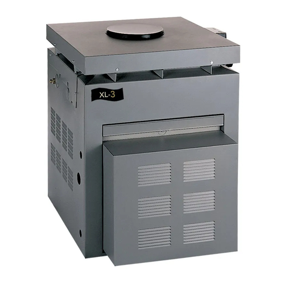
1.8.2 Dimensions 1.7.2 Materials for Special Applications 1.8 Specifications 1.8.1 General Specifications FRONT VIEW SIDE VIEW Figure 1. XL-3 Model DP3000 Oil-Fired Heater. -
Page 6: Installation Instructions
POOL PRODUCTS SECTION 2. Installation Instructions 2.1 Introduction WARNING CAUTION Figure 2. Inner Stack. 2.3 Location Requirements 2.3.1 Introduction CAUTION 2.2. Field Assembly or above... -
Page 7: Clearances
Table 1. Minimum Heater Clearances From Combustible Surfaces Note: Clearances listed in Table 1 are manufacturer's tested values. These are given as minimum values. Where local and national codes apply, and values are different than those listed in Table 1, use the greater value to ensure safe operation. -
Page 8: Outdoor Installation
POOL PRODUCTS 2.3.4 Outdoor Installation open, unroofed area 2.3.5 Indoor and Outdoor Shelter Installations WARNING United States Canada 2.3.5.1 Installing a Barometric Draft Control Figure 4. Outdoor Heater Installation. -
Page 9: Venting
SECTION 3. Venting 3.1 Combustion Air Supply Note: Table 2. Air Openings to Outside. Required Net Free Open Area* for Combustion Air Openings In Canada refer to the National Standard CAN1-B149.1 or .2 which differs from this table. Note: If using screens and/or metal louvers, compensate by adding 50% additional area to each opening If using wood louvers each opening must be at least four times the area indicated in the table above. -
Page 10: Exhaust Venting
POOL PRODUCTS WARNING 3.2 Exhaust Venting The only correct procedure for vent pipe sizing is to do so in accordance with these instructions and the applicable installation code as stated in the following "Danger" warning. DANGER 3.2.1 Outdoor Installations 3.2.2 Indoor and Outdoor Shelter Installations... -
Page 11: Fuel Connection
Figure 6. Venting, Indoor Installation. SECTION 4. Fuel Connections 4.1 Fuel Supply and Piping WARNING DO NOT ATTEMPT TO CONVERT THIS HEATER FOR USE WITH ANY OTHER TYPE OF FUEL. -
Page 12: Water Connection
POOL PRODUCTS Figure 8. Oil Filter Installation. SECTION 5. ONE-PIPE SYSTEM Water Connections 5.1 Water Piping TWO-PIPE SYSTEM Figure 7. One-Pipe and Two-Pipe Systems. Table 3. Fuel Line Sizes. Lift From Bottom of Total Tubing Total Tubing Storage Tank Length Allowed Length Allowed 5.2 Check Valve Installation to Fuel Pump... -
Page 13: Automatic Flow Control
Figure 9. Water Piping. 5.3 Automatic Flow Control Valve 5.4 Reversible Water Connections WARNING... -
Page 14: Connections At Heater
POOL PRODUCTS Figure 11. Connection Locations. 5.5 Connections at Heater Figure 10. Heat Exchanger Reversal. -
Page 15: Pressure Relief Valve
5.7 Auxiliary Components, Chlorinators, Ozone Generators, and Sanitizing Chemicals Figure 12. Water Connections. 5.6 Pressure Relief Valve Figure 13. Pressure Relief Valve. -
Page 16: Electrical
POOL PRODUCTS SECTION 6. 6.3 Bonding Electrical CAUTION CAUTION 6.1 General Information 6.4 Auxiliary Time Clock Wiring 6.2 Main Power The heater comes factory-wired intended for use with 115 VAC, 60 Hz, single phase field electrical supply (voltage may vary by ± 10%). Do not attempt to connect the heater to any other type of electrical source. -
Page 17: Operating Instructions
Figure 14. Wiring Diagram, 60 Hz Model. SECTION 7. Operating Instructions 7.1 Normal Operation... -
Page 18: Start Up
POOL PRODUCTS 7.2 Start-up WARNING CAUTION CAUTION CAUTION WARNING WARNING Figure 15. Inspection Hole Location. Figure 16. Heater's ON/OFF switch in OFF position. -
Page 19: Temperature Control
ONLY A QUALIFIED SERVICE TECHNICIAN MUST START THE OIL BURNER FOR THE FIRST TIME AND AFTER A PROLONGED PERIOD OF NON USE. Figure 17. Heater's Temperature control. 7.3 Temperature Control Important: 7.4 Lighting the Heater IMPORTANT: Caution... -
Page 20: Setting The Time Clock
POOL PRODUCTS 7.6 Adjusting the Water Pressure Switch CAUTION only Figure 18. Initial Air Adjustment. 7.5. Setting the Time Clock IMPORTANT: counterclockwise... -
Page 21: Temperature Rise
7.7 Temperature Rise Figure 19. Thermometer Placement. SECTION 8. Maintenance 8.1 Water Chemistry... -
Page 22: Seasonal Care
POOL PRODUCTS Water Pik does not warrant heat exchangers damaged by corrosive chemical levels or excess dissolved solids in pool or spa water. Table 4. Chemical Concentration Levels Test Recommended Level Figure 20. Heater Drains. 8.2.2 Winterizing The heater could be seriously damaged by freezing temperatures if it is not properly drained. -
Page 23: Spring Start-Up
8.3 Inspection and Service WARNING 8.3.1 Owner Inspection and Maintenance NOTE: 8.2.3 Spring Start-up... -
Page 24: Professional Inspection And Maintenance
POOL PRODUCTS NOTE 8.3.2 Professional Inspection and Maintenance Caution Caution DO NOT... -
Page 25: Trouble Shooting 9.1 Home Owner Trouble Shooting
9.1.4 Pool Water Overheating 9.2 Professional Troubleshooting Guide 9.2.1 Introduction SECTION 9. Troubleshooting 9.1 Home Owner Heater Troubleshooting WARNING 9.1.1 Oil Burner Does Not Fire 9.2.2 Initial Checks 9.1.2 Heater Does Not Maintain the Desired Water Temperature 9.1.3 Burner Operates, But There is Smoke or Pulsating Combustion... -
Page 26: Trouble Shooting
POOL PRODUCTS 9.2.3 Troubleshooting NOTE: Figure 21. Cad Cell and Primary Control. 9.2.3.1 Burner will not start (motor and transformer do not come on) 9.2.3.2 Burner Tries to Start, but the Primary Control Shuts Off (either motor or transformer or both come on) -
Page 27: Oil Burner Will Not Shut Off
9.2.3.4 Setting the Correct Fuel-Air Mixture Too Much Air Not Enough Air 9.2.3.3 Oil Burner Will Not Shut Off Figure 22. Electrode Adjustment. -
Page 28: Guide
POOL PRODUCTS 9.2.3.5. Control & Cad Cell SECTION 10. Troubleshooting Guide Replacement Parts Symptom Possible Cause 10.1 Ordering Information Burner runs all the time Defective primary control No combustion No power to the primary. Limit switch turned off. Defective limit switch. - Page 29 Model ORDER No. Description PART NO. FIRE BOX & JACKET COMPONENTS OIL BURNER PARTS & COMPONENTS (Not Shown) OPTIONAL EQUIPMENT...
-
Page 30: Exploded View
POOL PRODUCTS 10.3 Exploded View... - Page 31 NOTES...
-
Page 32: Limited Warranty
If the dealer is not available, you can locate a service center in your area by visiting www.jandy.com or by calling our technical support department at (707) 776-8200 extension 260. All returned parts must have a Returned Material Authorization number to be evaluated under the terms of this warranty.
Need help?
Do you have a question about the DP3000 and is the answer not in the manual?
Questions and answers