Table of Contents
Advertisement
IMPORTANT MANUAL
OWNER'S MANUAL
MODEL NUMBER:
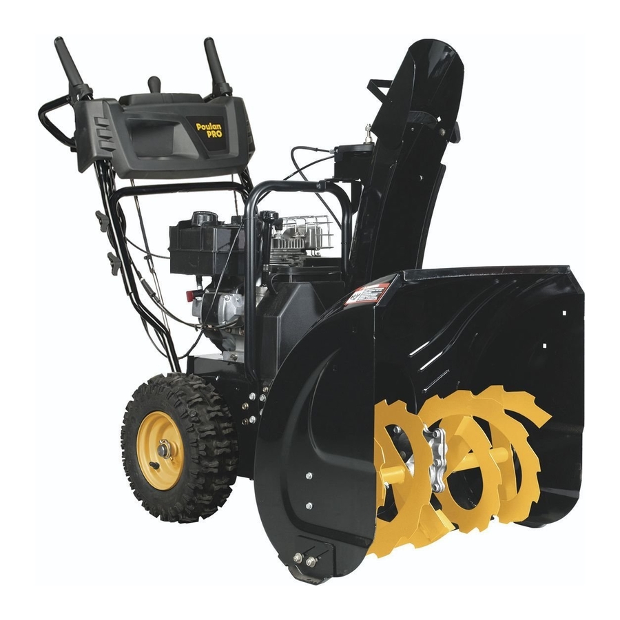
PR241
SNOW THROWER
Always Wear Eye Protection During Operation
Gasoline containing up to 10% ethanol (E10) is acceptable for use in this machine.
The use of any gasoline exceeding 10% ethanol (E10) will void the product warranty.
587 00 05-27 Rev. 2
Do Not Throw Away
WARNING:
Read the Owner's Manual and
fol low all Warnings and Safety
In struc tions. Fail ure to do so
can result in serious injury.
Advertisement
Table of Contents

Related Manuals for Poulan Pro PR241


Summary of Contents for Poulan Pro PR241
-
Page 1: Snow Thrower
Do Not Throw Away OWNER'S MANUAL MODEL NUMBER: WARNING: Read the Owner's Manual and PR241 fol low all Warnings and Safety In struc tions. Fail ure to do so can result in serious injury. SNOW THROWER Always Wear Eye Protection During Operation Gasoline containing up to 10% ethanol (E10) is acceptable for use in this machine. -
Page 2: Safety Rules
IMPORTANT Safe Operation Practices for Walk-Behind Snow Throwers This snow thrower is capable of amputating hands and feet and throwing objects. Failure to observe the following safety instructions could result in serious injury. WARNING: Snow throwers have ex- Look for this symbol to point out im- posed rotating parts, which can cause por tant safety precautions. -
Page 3: Table Of Contents
6. When cleaning, repairing or inspecting the snow 16. Never touch a hot engine or muffler. thrower, stop the engine and make certain the collector/ impeller and all moving parts have stopped. Disconnect Clearing a Clogged Discharge Chute the spark plug wire and keep the wire away from the Hand contact with the rotating impeller inside the discharge plug to prevent someone from accidentally starting the chute is the most common cause of injury associated with... - Page 4 PARTS PACKED SEPARATELY IN CARTON (1) MULTI- WRENCH (3) KNOB (180684) 581697501 (2) LOCKNUTS (2) SHEAR BOLTS 1/4-20 x 1-3/4 1/4-20 (585511801) (73800400) SAFTEY IGNITION KEY (S) (443059) (2) CARRIAGE BOLTS 5/16-18 x 2 1/4” (587359001) (1) LOCKNUT (1) CARRIAGE BOLT 5/16-18 5/16-18 x 5/8 (73970500)
-
Page 5: Assembly / Pre-Operation
ASSEMBLY / PRE-OPERATION Read these instructions and this manual in its entirety before you attempt to assemble or operate your new snow thrower. Reading the entire manual will familiarize you with the unit, which will assist you in assembly, operation and maintenance of the product. -
Page 6: Assembly / Pre-Operation
ASSEMBLY / PRE-OPERATION INSTALL DISCHARGE CHUTE / CHUTE ROTATOR HEAD INSTALL CHUTE DEFLECTOR REMOTE CONTROL (See Fig. 4 and 5) (See Figs. 6 and 7) 1. Install remote cable bracket to discharge chute with NOTE: The multi-wrench provided in your parts bag may 5/16-18 carriage bolt and 5/16-18 locknut as shown. -
Page 7: Operation
OPERATION KNOW YOUR SNOW THROWER READ THIS OWNER'S MANUAL AND ALL SAFETY RULES BEFORE OPERATING YOUR SNOW THROWER. Compare the illustrations with your snow thrower to familiarize yourself with the location of various controls and adjustments. Save this manual for future reference. These symbols may appear on your snow thrower or in literature supplied with the product. - Page 8 OPERATION DISCHARGE CHUTE CONTROL LEVER MUF FLER AUGER POWER CORD CONTROL PLUG GAS O LINE DRIVE SPEED LEVER FILLER CAP CON TROL LEVER ELECTRIC CHOKE START CON TROL DEFLECTOR BUTTON REMOTE ON / OFF CONTROL SWITCH LEVER TRACTION PRIM ER DRIVE CONTROL SAFETY...
- Page 9 OPERATION TO CONTROL SNOW DISCHARGE (See Fig. 11) The operation of any snow thrower can result in foreign objects thrown into the eyes, which WARNING: Snow throwers have ex- can result in severe eye damage. Always wear posed rotating parts, which can cause safety glasses or eye shields while operating severe injury from contact, or from ma- your snow thrower or performing any ad just-...
-
Page 10: Using The Clean-Out Tool
OPERATION USING THE CLEAN-OUT TOOL (See Fig. 13) TO MOVE FORWARD AND BACKWARD (See Fig. 14) In certain snow conditions, the discharge chute may SELF-PROPELLING, forward and reverse movement of become clogged with ice and snow. Use the clean-out tool the snow thrower, is controlled by the traction drive control to dislodge this blockage. -
Page 11: Before Starting The Engine
OPERATION BEFORE STARTING THE ENGINE TO ADJUST SKID PLATES (See Fig. 15) NOTE: The wrench provided in your parts bag may be CHECK ENGINE OIL LEVEL (See Fig. 16) used to adjust the skid plates. The engine on your snow thrower has been shipped from Skid plates are located on each side of the auger housing the factory already filled with oil. -
Page 12: To Start Engine
OPERATION TO START ENGINE 5. Pull recoil starter handle quickly. Do not allow starter rope to snap back. • Ensure fuel shut-off valve is in the “OPEN” position. 6. When the engine starts, release the recoil starter han dle Your snow thrower engine is equipped with both a 120 Volt and slowly move the choke control to the “OFF”... -
Page 13: Maintenance Schedule
MAINTENANCE LUBRICATION CHART GENERAL REC OM MEN DA TIONS ➀ The warranty on this snow thrower does not cover items SAE 5w30 Motor Oil that have been sub ject ed to operator abuse or negligence. ➁ See “Engine” in Maintenance section To receive full value from the warranty, operator must ➂... -
Page 14: To Change Engine Oil
MAINTENANCE SNOW THROWER Check the crankcase oil level before starting the engine and after each five (5) hours of continuous use. Tighten oil Always observe the safety rules when performing any fill cap / dipstick securely each time you check the oil level. main te nance. -
Page 15: Service And Adjustments
SERVICE AND ADJUSTMENTS To replace the shear bolts: WARNING: To avoid serious injury, before 1. Disengage all controls and move throttle control to performing any service or ad just ments: STOP position. Wait for all moving parts to stop. 1. Be sure the on/off switch is in the 2. -
Page 16: To Replace Belts
SERVICE AND ADJUSTMENTS TO REPLACE BELTS AUGER BELT REPLACEMENT (See Fig. 20) TO REMOVE AUGER BELT The auger and traction drive belts are not adjustable. If the belts are damaged or begin to slip from wear, they should 1. Remove upper 5/16” bolts and lower 1/4” bolts from be replaced. -
Page 17: Drive Belt Replacement
SERVICE AND ADJUSTMENTS AFTER REPLACING BELT(S) DRIVE BELT REPLACEMENT (See Fig. 21) 1. INSTALL BELT COVER and two (2) screws. Tighten TO REMOVE DRIVE BELT securely. 1. Remove auger belt. See “TO REMOVE AUGER BELT” 2. INSTALL DISCHARGE CHUTE – See “INSTALL in this section. -
Page 18: Service And Ad Just Ments
SERVICE AND ADJUSTMENTS TO ADJUST SPEED SELECT AND DRIVE ENGAGEMENT CABLE TENSION (See Fig. 23) CHUTE ROTATOR After many hours of use, if first gear seems to slip or seems CABLE too slow, adjustments may need to be made to the Speed Select and Drive Engagement cable tensions to shorten their lengths. -
Page 19: Storage
STORAGE Immediately prepare your snow thrower for storage at • Empty the fuel tank by starting the engine and letting it run until the fuel lines and car bu re tor are empty. the end of the season or if the unit will not be used for 30 days or more. -
Page 20: Troubleshooting
TROUBLESHOOTING See appropriate section in manual unless directed to an authorized service center/department. PROBLEM CAUSE CORRECTION Does not start 1. Fuel shut-off valve (if so 1. Turn fuel shut-off valve to OPEN position. equipped) in OFF position. 2. Safety ignition key 2. -
Page 21: Repair Parts
REPAIR PARTS SNOW THROWER - MODEL PR241 (96192008600) AUGER HOUSING / IMPELLER ASSEMBLY PART DESCRIPTION 581 63 73-02 AUGER HOUSING 532 40 78-25 SCRA PER BAR 872 27 05-05 CARRIAGE BOLT 5/16-18 X .625 GR5 532 15 53-77 NUT 5/16-18 05.09.010-C... - Page 22 REPAIR PARTS SNOW THROWER - MODEL PR241 (96192008600) AUGER HOUSING / IMPELLER ASSEMBLY 05.09.009-F NOTE: All component dimensions given in U.S. inches. 1 inch = 25.4 mm IMPORTANT: Use only Original Equipment Manufacturer (O.E.M.) replacement parts. Failure to do so could be hazardous, damage your snow thrower and void your warranty.
- Page 23 REPAIR PARTS SNOW THROWER - MODEL PR241 (96192008600) AUGER HOUSING / IMPELLER ASSEMBLY PART DESCRIPTION 586 71 48-01 GEARBOX AUGER 586 60 72-02 IMPELLER STEEL 586 71 52-01 PULLEY IMPELLER SCREW ON 585 05 69-01 CHUTE DISCHARGE BASE 532 18 40-95...
- Page 24 REPAIR PARTS SNOW THROWER - MODEL PR241 (96192008600) AUGER HOUSING / IMPELLER ASSEMBLY PART DESCRIPTION 532 19 21-99 TOOL CLEANOUT 532 40 54-00 CLIP CLEANOUT TOOL 532 19 41-89 SCREW HEX WASHER 13-16 X 5/8 05.09.039-A PART DESCRIPTION 532 42 04-78...
- Page 25 REPAIR PARTS SNOW THROWER - MODEL PR241 (96192008600) CONTROL PANEL / DISCHARGE CHUTE 05.08.002-D PART DESCRIPTION 581 12 83-01 CABLE CONTROL DRIVE 587 42 87-01 CABLE CONTROL AUGER 587 34 38-01 CABLE CONTROL SPEED 581 72 61-01 BOLT SHOULDER 1/4...
- Page 26 REPAIR PARTS SNOW THROWER - MODEL PR241 (96192008600) CONTROL PANEL / DISCHARGE CHUTE 05.08.003-D PART DESCRIPTION 581 68 03-01 CABLE ROTATOR ASM 581 32 94-01 PIN CLEVIS 5/16 X 7/8 877 10 08-12 PIN CLEVIS 1/4 X 3/4 532 42 33-03...
- Page 27 REPAIR PARTS SNOW THROWER - MODEL PR241 (96192008600) CONTROL PANEL / DISCHARGE CHUTE PART DESCRIPTION 580 66 47-01 CABLE INTERLOCK 532 43 17-62 PIN GROOVED 812 00 00-14 E-RING 581 15 12-01 SPRING RETURN 532 19 79-91 CLIP CABLE BLACK 05.08.001-B...
- Page 28 REPAIR PARTS SNOW THROWER - MODEL PR241 (96192008600) CONTROL PANEL / DISCHARGE CHUTE PART DESCRIPTION 581 13 12-01 CONSOLE BASE MULTI CONTROL 817 06 04-10 SCREW TA SEMI GIMLE 1/4-20 X .62 581 32 95-01 SCREW HEX WASHER 13-16 X 1.50 05.07.003-A...
- Page 29 REPAIR PARTS SNOW THROWER - MODEL PR241 (96192008600) CONTROL PANEL / DISCHARGE CHUTE PART DESCRIPTION 587 46 30-01 LEVER CONTROL DSST 581 20 81-01 LEVER PIVOT CONTROL ASM 585 69 07-01 SCREW HEX HD 10-24 X 1.50 532 43 17-62...
- Page 30 REPAIR PARTS SNOW THROWER - MODEL PR241 (96192008600) CONTROL PANEL / DISCHARGE CHUTE PART DESCRIPTION 532 44 36-24 CHUTE WELDMENT 532 18 45-11 DEFLECTOR WELDMENT 532 42 03-25 DEFLECTOR SEAL 532 12 84-15 POP RIVET 532 43 03-24 CHUTE SNOW SHIELD...
- Page 31 REPAIR PARTS SNOW THROWER - MODEL PR241 (96192008600) HANDLES PART DESCRIPTION 581 12 36-04 UPPER HANDLE 532 19 19-38 HANDLE KNOB STD BLACK 587 35 90-01 BOLT 5/16-18 X 1.75 CONCAVE HEAD 05.06.001-E PART DESCRIPTION 581 12 35-04 LOWER TUBE...
- Page 32 REPAIR PARTS SNOW THROWER - MODEL PR241 (96192008600) DRIVE 05.02.001-C NOTE: All component dimensions given in U.S. inches. 1 inch = 25.4 mm IMPORTANT: Use only Original Equipment Manufacturer (O.E.M.) replacement parts. Failure to do so could be hazardous, damage your snow thrower and void your warranty.
- Page 33 REPAIR PARTS SNOW THROWER - MODEL PR241 (96192008600) DRIVE PART DESCRIPTION 585 69 1501 NUT HEX FLANGE LK 5/16-18 580 75 6201 BEARING 9/16 I.D. 1622-2RSNR 532 17 5344 TRUNNION BEARING ASM 872 11 0506 BOLT CARRIAGE 5/16-18 X .75 GR5...
- Page 34 REPAIR PARTS SNOW THROWER - MODEL PR241 (96192008600) DRIVE 05.03.001-A PART DESCRIPTION 532 44 49-49 WASHER 1.00 581 12 23-01 HEX BUSHING 1 SHAFT 812 00 00-53 RETAINER RING 581 12 22-02 GEAR 80T DRIVEN 532 17 12-71 RIVET RD HD DRILLED 1/4 DIA...
-
Page 35: Repair Parts Chassis/Engine/Pulleys
REPAIR PARTS SNOW THROWER - MODEL PR241 (96192008600) CHASSIS / ENGINE / PULLEYS PART DESCRIPTION 05.01.001-C 580 42 60-05 COMPLETE LCT ENGINE PW2HK18650178E 580 83 94-03 FRAME 532 15 04-06 ENGINE BOLT 3/8-16 X 1.280 DOGPOINT 580 83 95-03 FRAME COVER... - Page 36 REPAIR PARTS SNOW THROWER - MODEL PR241 (96192008600) CHASSIS / ENGINE / PULLEYS PART DESCRIPTION 587 10 54-01 BELT COVER BLACK 585 69 11-01 BOLT HEX WSH THDRL 1/4-20 X 1 532 14 50-06 CABLE GUIDE 532 42 30-62 PALNUT 1/4 IN 05.04.002-B...
- Page 37 REPAIR PARTS SNOW THROWER - MODEL PR241 (96192008600) CHASSIS / ENGINE / PULLEYS 05.04.001-G PART PART DESCRIPTION DESCRIPTION 581 62 37-02 BELT KEEPER BRACKET 581 41 38-01 SHOULDER BOLT 819 11 12-16 WASHER 11/32 X 3/4 X 16 GA 5/16-24 X 2.15...
- Page 38 REPAIR PARTS SNOW THROWER - MODEL PR241 (96192008600) WHEELS PART DESCRIPTION 580 62 77-03 WHEEL 13X4 NPS RH 1.00 K478 580 62 76-03 WHEEL 13X4 NPS LH 1.00 K478 05.15.001-A NOTE: All component dimensions given in U.S. inches. 1 inch = 25.4 mm IMPORTANT: Use only Original Equipment Manufacturer (O.E.M.) replacement parts.
- Page 39 REPAIR PARTS SNOW THROWER - MODEL PR241 (96192008600) BAG OF PARTS PART DESCRIPTION 9 10 585 51 18-01 BOLT 1/4- 20 X 1.81 873 80 04-00 NUT NYLOCK 1/4-20 532 42 91-12 WRENCH 585 83 22-01 BOLT SHOULDER 585 69 14-01...
- Page 40 REPAIR PARTS SNOW THROWER - MODEL PR241 (96192008600) DECALS PART DESCRIPTION 532 18 40-45 DECAL AUGER 532 19 96-82 DECAL CHUTE 532 19 96-83 DECAL AUGER SAFETY 532 18 40-28 DECAL BELT GUIDE 05.16.001-A NOTE: All component dimensions given in U.S. inches.
- Page 41 REPAIR PARTS SNOW THROWER - MODEL PR241 (96192008600) DECALS KEY PART DESCRIPTION 532 19 96-83 DECAL, DANGER 532 19 96-82 DECAL, DANGER, DEFLECTOR 532 18 40-45 DECAL, DANGER 532 18 40-28 DECAL, BE H GUARD 587 00 05-27 OWNER’S MANUAL, ENGLISH 587 00 05-31 OWNER’S MANUAL, FRENCH...
-
Page 42: Engine Breakdown
REPAIR PARTS SNOW THROWER - MODEL PR241 (96192008600) COMPLETE ENGINE-580426005 KEY PART KEY PART DESCRIPTION DESCRIPTION 532 42 05-78 CYLINDER HEAD ASSEMBLY - 532 44 66-42 CRANKSHAFT (#18 KEYED 208CC (INCL. GASKET) 208CC SNOW) 532 42 05-79 PUSH ROD & PLATE KIT (208CC) 532 43 65-63 MUFFLER ASSEMBLY-GEN LL (INCL. - Page 43 REPAIR PARTS SNOW THROWER - MODEL PR241 (96192008600) COMPLETE ENGINE-580426005 KEY PART KEY PART DESCRIPTION DESCRIPTION 532 42 49-39 SPARK PLUG 532 42 49-69 HIGH OIL-FILL TUBE/DIPS- 532 42 49-57 ON/OFF SWITCH - ROCKER TICK (THREADED) (SN 532 43 21-44 FUEL HOSE KIT (1/4’’ ID X 318MM <1265H0519257)
-
Page 44: Warranty
LIMITED WARRANTY The Manufacturer warrants to the original consumer purchaser that this product as manufactured is free from defects in materials and work man ship. For a period of two (2) years from date of purchase by the original consumer purchaser, we will repair or replace, at our option, without charge for parts or labor incurred in replacing parts, any part which we find to be defective due to materials or workmanship.
Need help?
Do you have a question about the PR241 and is the answer not in the manual?
Questions and answers