Table of Contents
Advertisement
Quick Links
Advertisement
Table of Contents

Related Manuals for Cooper Security 9751


Summary of Contents for Cooper Security 9751
- Page 1 INSTALLATION GUIDE HARDWIRED CONTROL UNIT...
- Page 2 © Cooper Security Ltd. 2009 Every effort has been made to ensure that the contents of this book are correct. However, neither the authors nor Cooper Security Limited accept any liability for loss or damage caused or alleged to be caused directly or indirectly by this book. The contents of this book are subject to change without notice.
-
Page 3: Table Of Contents
Contents 1. INTRODUCTION..................1 About this Manual ............................1 Features of the Control Unit .........................2 Elements of the IAS .............................3 9941 and 9943 Keypads ..........................5 Expanders ..............................5 Partitioned or Single System........................7 User Control ..............................7 2. TECHNICAL DESCRIPTION ............... 9 Control Unit Specification..........................9 General..............................9 Power Supply ............................9 Outputs ..............................10... - Page 4 Contents 9751 Installation Guide List of Figures Figure 1. Elements of an Intruder Alarm System..................4 Figure 2. 9941 and 9943 Keypads .......................5 Figure 3. Control Unit PCB Layout......................12 Figure 4. Star and Bus Wiring for Keypads and Expanders ...............14 Figure 5. Backplate of the 9941/9943 Keypad ...................16 Figure 6.
-
Page 5: Introduction
This manual is divided into three chapters: 1. Introduction: this describes the parts of an Intruder Alarm System (IAS) based on the 9751 control unit. 2. Technical description: this defines the operating parameters of the different parts of the system. -
Page 6: Features Of The Control Unit
1. Introduction 9751 Installation Guide Features of the Control Unit The control unit provides: ° On-board connections for 8 Fully Supervised Loop (FSL) zones or 8 Closed Circuit Loop (CCL) zones with a common tamper. Separate expander units enable a further 16 zones to be connected: a combination of wired and radio expanders can be used. -
Page 7: Elements Of The Ias
9751 Installation Guide 1. Introduction Elements of the IAS An IAS comprises a control unit in a shielded case, with 1 to 4 separate keypads and various detectors, transmitters and other devices connected to programmable zones. If required, a keyswitch can be connected to a zone. -
Page 8: Figure 1. Elements Of An Intruder Alarm System
1. Introduction 9751 Installation Guide 1. 723r EUR Telecommand 9. 9954 hardwired expander 2. 726r EUR PA 10. Passive Infra Red detectors 3. 714r EUR wirefree Passive Infra Red detectors 11. Keypads 4. RFX radio expander 12. Door contacts 5. 735r EUR universal transmitter 13. -
Page 9: 9941 And 9943 Keypads
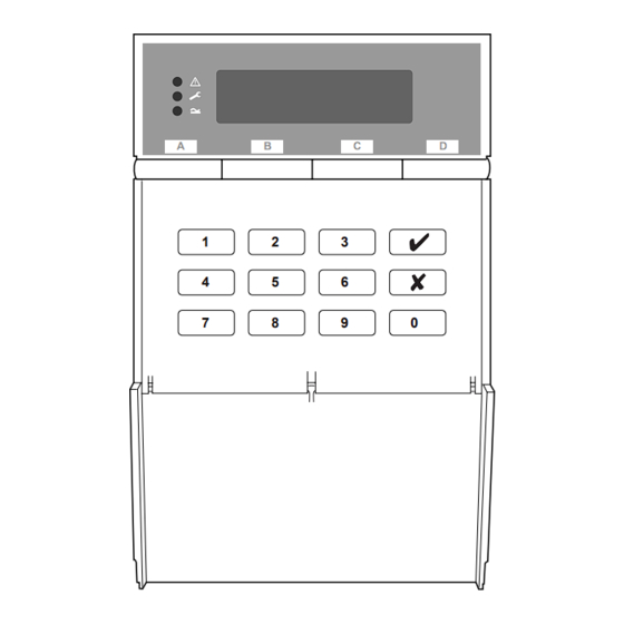
9751 Installation Guide 1. Introduction 9941 and 9943 Keypads Figure 2. 9941 and 9943 Keypads The control unit supports the connection of 9941 and 9943 keypads. The 9943 has a built-in wide-area proximity reader and connections for an external panic alarm switch. Both have a two-line 16-character Liquid Crystal Display (LCD) that can display alarm information, programming settings and other information. - Page 10 1. Introduction 9751 Installation Guide 2. Two-wire Fully Supervised Loop (FSL). Radio Expanders ° 703r. Four channel programmable transmitter, when used in two door contact mode only. ° 710r. A compact, long range, two button PA transmitter. ° 713r and 714r. These are Passive Infra-Red (PIR) movement detectors.
-
Page 11: Partitioned Or Single System
9751 Installation Guide 1. Introduction Partitioned or Single System During installation, the Installer can configure the system as a single system or as a partitioned system. In a single system, the control unit has one full set level (security level A) and three part set security levels (levels B, C and D). - Page 12 1. Introduction 9751 Installation Guide Page 8 11976798...
-
Page 13: Technical Description
To comply with the requirements of EN50131, the total current taken from the power supply, not including the battery recharge current, but including auxiliary outputs and other devices, must not exceed 750mA. Nominal power requirements (DC): 9751 130mA quiescent, 220mA active 9941 20mA quiescent, 60mA backlight on... -
Page 14: Outputs
12. Cooper Security Ltd recommend that you fit at least a 7Ah battery. Note that a 17Ah battery cannot fit inside the case. -
Page 15: Compatible Equipment
9751 Installation Guide 2. Technical Description Compatible Equipment 703rEUR-00 Programmable four channel transmitter 710rEUR-00 Long range, compact, dual button PA transmitter 713rEUR-00 Pet tolerant wireless PIR detector (10m range) 714rEUR-00 Wireless PIR detector (15m range) 720rEUR-00 Wireless Smoke Detector 722rEUR-00... -
Page 16: Control Unit Pcb Layout
2. Technical Description 9751 Installation Guide Control Unit PCB Layout Figure 3 shows the layout of the PCB used in the control unit. 1. Outputs (3 open collector outputs) 8. NVM Reset pins 2. AUX power 9. Plug-by (standalone) communicator connector 3. -
Page 17: Installation
3. INSTALLATION Caution: Always remove mains power before opening the case lid. Do not work inside the control unit with mains power present. Overview A typical installation comprises the following main steps: Survey the site and decide on positions for wired detectors, 9954 wired expanders, control unit, keypads, external and internal sounders. -
Page 18: Cabling For Keypads And Expanders
9751 Installation Guide Cabling for Keypads and Expanders Cooper Security recommends that you use 8-core 7/0.2 or 16/0.2 alarm cable for wiring keypads and expanders. You can connect the keypads and expanders in either a star or bus configuration (see Figure 4). If you intend to use long cable runs, Cooper Security recommends that you use star wiring with no more than 200m of cable per branch. - Page 19 9751 Installation Guide 3. Installation It is possible to extend the keypad cable run by using additional power supplies, but only up to the recommended maximum of 200m. When carrying out the cabling, there are two important points to remember: 1.
-
Page 20: Fitting The System
4. Sounder aperture. Figure 5. Backplate of the 9941/9943 Keypad Cooper Security recommend that you mount the keypad using No 8 or 6 screws (M4/M3.5) as follows: Select which cable entry you are going to use and break out the appropriate plastic sections. -
Page 21: Wiring The Control Unit
9751 Installation Guide 3. Installation Hold the backplate in place against the wall and mark the position of one fixing hole. Drill and plug the hole, and screw the backplate to the wall. Do not tighten the screw completely home. -
Page 22: Keypads
3. Installation 9751 Installation Guide Caution: Do not apply mains power at this point. Do not work inside the control unit case when mains power is present. Keypads Connecting Keypads Figure 7 shows the connections for keypads. Use the "ET" connector terminals on the keypad PCB to connect an exit terminate button or lock switch. -
Page 23: Connecting Sounders
9751 Installation Guide 3. Installation Keypad Addressing The control unit is supplied with one keypad. If you have fitted more keypads, each one must be given a separate "address". Links LK2 to LK4 set the keypad address, as shown in Figure 9. -
Page 24: Figure 10. Sounder Connections
3. Installation 9751 Installation Guide To Bell Box 6-core Internal Sounder Figure 10. Sounder Connections Lyntech Ltd - 120 LED/120 lexon Control Unit 12V AUX Terminals Bell-Box STRB HOLD + Terminals Elmdene Rapier 300, 4000, 5000, 6000; Prima 100-600; Starlight 020... -
Page 25: Connecting Detector Circuits To The Main Pcb
9751 Installation Guide 3. Installation Connecting Detector Circuits to the Main PCB The connectors for the detector circuits, or zones, are on the left-hand edge of the main PCB in the control unit. The table below summarises the number and type of zones that can connect to the main PCB of the control unit. Use Command 21 to specify which of these wiring types you are using. -
Page 26: Figure 12. Fsl Connections
3. Installation 9751 Installation Guide tamper device opens, the loop resistance becomes infinite (open circuit) and so the control unit detects a tamper signal. To connect a detector to an FSL loop, you must wire suitable high-tolerance resistors to the detector. Always check resistor colour coding and tolerance before wiring resistors into circuit (see Figure 13). -
Page 27: Figure 14. Wiring Zones That Use Anti-Masking
• Method 1: Using two pairs of contacts at the sensor. One pair reports the alarm/tamper status and the other reports the anti-masking status. This method requires two adjacent zones to be used at the 9751 control unit (one for each pair of contact at the sensor), with the highest zone number for anti-masking. -
Page 28: Connecting Expanders
9954 Hardwired Expander The 9954 hardwired expander provides connectors for eight CCL, FSL or EOL zones (EOL zones are not relevant for the 9751). Figure 15 shows the layout of the PCB. See the wiring diagram supplied with the 9954 hardwired expander for more details. -
Page 29: Figure 16. Rfx08/Rfx16 Radio Expander
9751 Installation Guide 3. Installation Red "Fail" LED Radio section Green "Pass" LED Learn sensor Sounder Supervision jumper 2 x 7-segment display Jamming response jumper Select button Address jumpers Delete button Bus connector Built-in aerial Cable entry Tamper switch Figure 16. RFX08/RFX16 Radio Expander Refer to the "Installation and Programming Guide"... -
Page 30: Programming Outputs
3. Installation 9751 Installation Guide When fitting a 9954 hardwired expander, make sure that you place the jumper link on the expander in the correct position to select either four-wire CCL, or two-wire FSL (see Figure 18). Figure 18. Link Positions to Select Wiring Method Once you have connected an expander, refer to the instructions supplied with it for connecting hardwired detectors or "learning"... -
Page 31: Wiring Keyswitches
9751 Installation Guide 3. Installation Figure 20. Wiring Examples for Open Collector Outputs Wiring Keyswitches To allow a user to set and unset the system using a keyswitch, connect a fixed position or spring loaded (momentary) key switch to a zone input. When programming the control unit select zone type (KM) for momentary or (KF) for fixed position keyswitches. -
Page 32: Communicator
3. Installation 9751 Installation Guide Communicator Connecting the Communicator The control unit has an internal communicator on its main PCB. This is an auto-dialling modem. If necessary, a standalone communication device can be connected through a wiring harness to interface pins on the main PCB (this is known as a plug-by communicator). -
Page 33: Statutory Information
9751 Installation Guide 3. Installation Test Calls The control unit can be programmed to make test report calls to an ARC. "Static" test calls can be programmed to occur at set times or intervals. "Dynamic" test calls occur 24 hours after the last call made by the unit. See the Programming Guide for details on how to program these functions with Commands 105 and 108. -
Page 34: Safety Notice
3. Installation 9751 Installation Guide Ringer Equivalence Number The Ringer Equivalence Number (REN) of the built-in communicator is 1. As a guide to the number of items that can be simultaneously connected to an exclusive line, the sum of the REN values should not exceed 4. A standard telephone (as provided, for example, by BT in the UK) has a REN value of 1. -
Page 35: Figure 22. Selv And Tnv Connectors
9751 Installation Guide 3. Installation 1. Main connector (SELV) 5. Wire in comms connector (SELV) 2. Keypad connector (SELV) 6. Battery connector (SELV) 3. Telephone line connector (TNV) 7. 21VAC from transformer (SELV) 4. RJ11 connector (TNV) Figure 22. SELV and TNV connectors... -
Page 36: Connecting The Telephone Line
3. Installation 9751 Installation Guide Connecting the Telephone Line Connecting the telephone line directly to the terminals on the internal communicator, or indirectly through other apparatus, can produce hazardous conditions on the telephone network. Always seek advice from a competent telephone engineer if in any doubt about connecting to these terminals. -
Page 37: Fitting A Plug-By Communicator
9751 Installation Guide 3. Installation Fitting a Plug-by Communicator The control unit can be fitted with a communicator or speech dialler (for example, the Scantronic 8400, 8440, 660 or RedCare STU). Figure 24 shows the connections for the communications wiring harness. -
Page 38: Figure 26. Fitting Control Unit Pcb
3. Installation 9751 Installation Guide Make any necessary connections from the communicator to the communication wiring harness. The default is a positive voltage when the output is inactive but this can be inverted if required using Command 159. Refer to the next section if you are using a dual-path communicator. -
Page 39: Fitting A Battery
Fit a rechargeable battery into the back of the case. There is space in the case for a 12V 7Ah battery; make sure the battery terminals are oriented in the position shown in Figure 27. Cooper Security Ltd recommend that you fit at least a 7Ah battery. Figure 27. Fitting a Battery 11976798... -
Page 40: Initial Start Up
3. Installation 9751 Installation Guide Initial Start Up Before applying power to the control unit, ensure that: • All keypads and expanders have been addressed and connected. • All external and internal sounders are connected. • All wired zone circuits are connected. -
Page 41: Index
Index 9954 PCB layout............24 connecting ...............18 Access code..............7, 36 power requirements ..........9 Auxiliary output .............10 tamper switch ............16 Battery Kick start pins..............36 fitting ................35 Learning specification.............10 wirefree detectors......... 6, 13, 26 Bell Line tamper return............10 line fault input ............10 Bell-box connections.............19 monitoring/faults .......... - Page 42 Index 9751 Installation Guide Transmitter Zone PA transmitter ............. 6, 11 CCL ................. 21 universal ............. 6, 11 FSL................21 Universal transmitter ..........6, 11 wiring............... 21 Weight ................9 Page 38 11976798...
- Page 43 9751 Installation Guide Index 11976798 Page 39...
- Page 44 Cooper Security Ltd. Security House Vantage Point Business Village Mitcheldean Gloucestershire GL17 0SZ www.scantronic.co.uk Product Support (UK) Tel: +44 (0)1594 541979 Available between: 08:15-12:30 and 13:00-17:00 Monday to Friday. Product Support Fax: +44 (0)1594 545401 Part Number 11976798 Declarations of conformance to standards can be obtained from our Web site, www.coopersecurity.co.uk...
Need help?
Do you have a question about the 9751 and is the answer not in the manual?
Questions and answers