Table of Contents
Advertisement
Quick Links
Download this manual
See also:
Operating Manual
Advertisement
Table of Contents

Related Manuals for Intellian i2


Summary of Contents for Intellian i2
- Page 1 Installation and Operation User Manual Document Number: 2012D0-UM1004-V1_0...
- Page 2 Intellian Technologies, Inc., and should not be appropriated without permission by Intellian Technologies, Inc., and the information contained in this manual is the property of Intellian Technologies, Inc. Any and all parts of this manual shall not be reproduced and distributed in any form without prior written consent by Intellian Technologies, Inc.
-
Page 3: Table Of Contents
INTRODUCTION OPERATION USING PC CONTROLLER PROGRAM INTRODUCTION TO INTELLIAN i2 INTRODUCTION FEATURES OF INTELLIAN i2 PROGRAM INITIALING AND SERIAL PORT SETUP BASIC SYSTEM CONFIGURATION OF INTELLIAN i2 MAIN MENU CONTROLLER MENUS INSTALLATION PREPARATION FOR TRANSPORTATION SYSTEM COMPONENTS TOOLS REQUIRED FOR INSTALLATION... -
Page 4: Introduction
For flexibility, there is a second RF connector on the antenna base. In addition, the i2 has adopted a built-in GPS interface (NMEA 0183,) allowing boaters to plug-in an external GPS to speed up acquisition... -
Page 5: Features Of Intellian I2
Enjoy satellite broadcasts at sea installation easy. Power, RF, and Data signals transfer from the antenna Intellian i2 is the most modern antenna system that enables you to to the ACU through this single cable. receive high quality broadcasting signals at sea where the atmospheric and environmental conditions are very harsh. -
Page 6: Basic System Configuration Of Intellian I2
Separate purchase of a satellite receiver and a TV is required. Satellite Receiver Satellite Receiver (Not Supplied) (Not Supplied) Note: Dish Network and Bell TV users please refer to the Intellian Dish Network MIM Installation and User Manual. Antenna Control Unit ANT RF1 RECEIVER DC 9~30V... -
Page 7: Installation
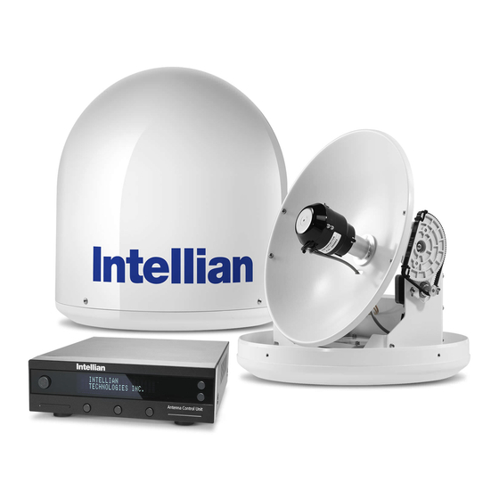
Installation The components of the Intellian i2 have been designed to be modular so that it is suitable for simple installation on all types of vessels. System Components Antenna Unit The antenna of Intellian i2 is comprised with the following components for optimum search and reception of the satellite signal. - Page 8 Intellian Satellite TV Antenna Systems Antenna Control Unit (ACU) Front The Antenna Control Unit (ACU) provides the power to the antenna and controls various settings of the antenna. The digital VFD (Vacuum Fluorescent Display) allows for easy operation of the ACU, even in the dark.
- Page 9 Installation Kit Other Components Contains the items required for securing the antenna unit and ACU to the vessel. Components Size ACU Bracket Antenna RG6(Antenna – ACU RF Cable) RG6(ACU – IRD Cable) Power Cable Item PC Serial Cable 1.8m Spring Washer Hex.Bolt Flat Washer Hex.
-
Page 10: Tools Required For Installation
Intellian Satellite TV Antenna Systems Tools Required for Installation Power Drill Power Drill 11 mm Spanner 11 mm Spanner 8 mm Drill Bit 8 mm Drill Bit Pencil Pencil Cross-Head Cross-Head Ø50 mm Ø50 mm Screwdriver Screwdriver 10 mm Spanner... -
Page 11: Planning The Installation
Planning the Installation Selection of Installation Site Install the antenna in accordance with the following procedures to ensure maximum performance of the antenna. The antenna should be installed in a place where it has an all-round clear view of the horizon. Please be sure there are no obstacles within 15°... -
Page 12: Power Requirements
RF cable supplied by system. Intellian Technologies. • Intellian i2 has been designed to work on a boat’s power supply rated at 12V / 24V DC (acceptable range: 9~30 V DC). • If your IRD(s) and television(s) require a 110V/240V AC power supply,... -
Page 13: Installation And Mounting Of Antenna
Before installing the antenna, open the radome and remove the Note: shipping constraints from the antenna interior. Reinstall the radome before operating the system. The system will not perform properly if the Ø37 cm (14.7”) radome is open. Figure 08 : Radome Dimension of i2... - Page 14 RF connector from being exposed to sea water and external shocks. An power tower by drawing a square of 14.4cm (5.7”) exposed cable may cause electric shock and cause serious damage to the equipment. 14.4cm (5.7”) Figure 09 : Intellian i2...
- Page 15 Securing Holes for Bolts and Cable Ways Connection of the Cable Make 4 bolt holes of 8mm diameter, one at each corner of a rectangle Remove the rubber cap from RF connector. Connect the RF cable to the drawn as below, and make a circular hole of 50mm diameter at the RF connector under the base plate through the access hole using an center of the rectangle through which the cable will run.
-
Page 16: Installing The Acu
Intellian Satellite TV Antenna Systems Installing the ACU ACU Dimensions Mounting the Antenna Fix the antenna to the holes made before as shown in the drawing below by using the hex head bolts (M6 X 35L), M6 spring washer, M6 flat washer and M6 Nut supplied. -
Page 17: Selecting Acu Installation Site
Selecting ACU Installation Site The ACU should be installed below deck, in a location that is: • Dry, cool, and ventilated. • Easily accessible from your main TV viewing area. To Install the ACU 1. The ACU should be installed using the two supplied mounting brackets which allow for a top or bottom mounting configuration. -
Page 18: Connecting The System Cables
Intellian Satellite TV Antenna Systems Connecting the System Cables After installation and fixation of the antenna, connect the ACU to the antenna. Refer to the drawing below to connect cables. Single IRD Connection • Connect the RF Cable (15m) from the RF 1 connector on the antenna to the ANT. - Page 19 Twin IRDs Connection You can connect two IRDs for your antenna as shown in the following RF1 RF2 diagram. One of the IRD’s need to be set up with the ACU in order to use another IRD without connecting the ACU. Both IRD’s with and without an ACU connection can receive any channels that are available from the IRD2 (Not Supplied) tracked satellite.
- Page 20 Intellian Satellite TV Antenna Systems Multiple-IRDs Connection In order to connect multi-IRD to the antenna, you will need to purchase RF1 RF2 a suitable multiswitch. The multiswitch has to be installed between the antenna unit and the IRDs as shown on the right.
-
Page 21: Connecting The System To A Gps
NMEA 0183 GPS system. To do this you will need a cable with suitable lengths to connect to your GPS system and you will ANT RF1 RECEIVER need the green 2-way ACU GPS connector supplied with your Intellian i1/i2 Satellite TV System. DC 9~30V FUSE... -
Page 22: Adjusting The Lnb Skew Angle (Linear Polarization Only)
Figure 19 : Manual Angle Adjustment LNB Skew Skew Angle Adjustment for i2 Polarization of your Intellian i2 antenna must be accomplished manually by the following steps. • Remove the upper part of the Radome after switching the power OFF. -
Page 23: Operation Instruction
Operation Instruction Introduction This section of the handbook describes how to setup your Satellite TV System after installing the ACU. It includes the following functions: • System start up. • Changing the default satellite. • Monitoring the antenna status. • Setting sleep mode. •... -
Page 24: Operating Using The Acu
Intellian Satellite TV Antenna Systems Operation Using the ACU ACU Soft Keys Normal Mode Start Up With the system installed and power applied, the ACU screen will show the following sequence: 1. Data communication is being established INITIALIZE ACU between the antenna and the ACU. The ACU INTELLIAN i2 is initialized. - Page 25 Advanced Tri-Sat Mode Changing Target Satellite Your antenna is programmed with two candidates for target satellites as the default Dual-sat mode. Use advanced Tri-sat mode for targeting three satellites. To change the target satellite, press the LEFT soft key. The target satellite is changed and is automatically tracked by the antenna.
- Page 26 Intellian Satellite TV Antenna Systems Monitoring the Current Status of the Antenna While the power is ON on the Intellian i2, ACU displays the status of the antenna. The various ACU displays may be shown according to the current status of the antenna.
-
Page 27: Setup Mode
Setup Mode Sleep Mode Begin Setup Mode If the antenna loses the tracking satellite while in sleep mode, sleep To enter the Setup Mode simply follow the instructions below. mode will be cancelled. 1. Press BACK to enter sleep mode. 1. - Page 28 Intellian Satellite TV Antenna Systems Setting the Satellite Pair You can change the satellite pair if you decide to receive satellite television service from a different service provider. 1. Press YES to enter setup mode. 5. Set satellite B SETUP MODE ? SAT B : DTV119 Press PREV to show previous satellite name.
- Page 29 Setting GPS It is possible to set up and modify the GPS information, which enhances the antenna functionality. 5. Press ENTER to move to next screen. 1. Press YES to enter setup mode. LONGITUDE ###.## E SETUP MODE ? Press BACK to move to previous screen. INPUT 6.
- Page 30 Intellian Satellite TV Antenna Systems Edit Satellite Information It is possible to modify the existing satellite information and input new satellite information into the ACU as well. It is not recommended for a novice satellite service user to use this mode.
- Page 31 13. Input the network ID (NID) for vertical high 9. Input the network ID (NID) for vertical low band. VER HIGH NID 0x0003 VER LOW 12523 21096 band. INPUT INPUT 14. Input the tracking frequency (MHz) and symbol 10. Input the tracking frequency (MHz) and symbol HOR LOW 12523 21096 HOR HIGH 12523 21096 rate (KHz) for horizontal high band.
- Page 32 Intellian Satellite TV Antenna Systems Verification Method* 17. Select the Voltage Supply Method* to LNB. VOLTAGE : AUTO SIGNAL - use only signal level for tracking (AUTO is recommended) PREV SELECT NEXT DVB LOCK - use only DVB Lock signal for tracking...
- Page 33 Setting the Antenna Parameters It is not recommended for a novice satellite service user to use this mode. Consult Intellian for changing antenna parameters. 1. Press YES to enter setup mode. 5. Input the WRS LEVEL. WRS LEVEL : 0500 SETUP MODE ? + increases the value.
- Page 34 Intellian Satellite TV Antenna Systems PARAM* Scan Offset DiSEqC Level The scan offset is to offset the angle difference between the The DiSEqC level is to distinguish 0KHz tone and 22KHz tone. black marker on the sub-reflector and the optical sensor.
- Page 35 Setting the LNB Local Frequency It is possible to select a local frequency from ACU. It is not recommend- ed for a novice satellite service user to use this mode. Case1. Single band LNB is used. 1. Press YES to enter setup mode. 5.
- Page 36 Intellian Satellite TV Antenna Systems Case 2. Universal LNB is used (Low band local frequency-9750 MHz/ High band local frequency 10600 MHz). 1. Press YES to enter setup mode. 5. Press YES to accept the data. SETUP MODE ? SAVE ? Press NO to cancel and return to main setup mode.
- Page 37 Setting the DiSEqC Method DiSEqC selection can be made from ACU. It is not recommended for a novice satellite service user this mode. 5. Press YES to accept the selection. 1. Press YES to enter setup mode. SAVE ? SETUP MODE ? Press NO to cancel and return to main setup mode.
- Page 38 Intellian Satellite TV Antenna Systems Display Versions This sequence enables you to see what version of antenna and ACU software are installed on your system. 1. Press YES to enter Display Version. 5. Antenna software version and S/N are shown.
- Page 39 Display Power 1. Press YES to enter setup mode. 5. Antenna input voltage is shown. SETUP MODE ? ANT POWER : 25.9 V Press center soft key to view IRD Voltage and EXIT frequency. Press EXIT to return to main setup mode. 2.
- Page 40 Intellian Satellite TV Antenna Systems Setting Remote Control 5. SELECT/ENTER - Registers a key on remote 1. Press YES to enter setup mode. FUNC : SLEEP MODE SETUP MODE ? control. NEXT SELECT EXIT 6. Point remote control to ACU.
- Page 41 9. REMOTE KEY REGISTED will be displayed if key REMOTE KEY REGISTED has been properly registered. 10. Press NEXT to shows next function. FUNC : CHANGE SAT Press EXIT to return to main setup mode. NEXT SELECT EXIT Function* CHANGE SAT - Change the target satellite. SLEEP MODE - Enter sleep mode.
- Page 42 Intellian Satellite TV Antenna Systems Setting Antenna Go Position The antenna can be controlled manually by using the ACU. 1. Press YES to enter setup mode. 5. Input position value for elevation (EL) axis. SETUP MODE ? GO TO EL : ##.# + increases the value.
- Page 43 Setting the Antenna Move Step The antenna can be moved by 1° step manually by using ACU. 1. Press YES to enter setup mode. 5. Move the antenna in the EL axis. SETUP MODE ? STEP EL : ##.# UP - Move the antenna up. DOWN EXIT DOWN - Move the antenna down.
- Page 44 Intellian Satellite TV Antenna Systems Executing Antenna Diagnosis It is possible to see the antenna’s status by reviewing the results of diagnosis of the antenna. Refer to the following codes to understand the diagnosis results. 1. Press YES to enter setup mode.
- Page 45 CODE* CODE 101 Data communication between antenna and antenna control unit is CODE 107 Skew System is tested. tested. If failed, check the RF cable. if failed, check the control board, skew motor, and skew sensor. CODE 102 AZ CW limit is tested. CODE 108 Antenna Input Power is tested.
- Page 46 Intellian Satellite TV Antenna Systems Setting Region 1. Press YES to enter setup mode. 5. Select the Region*. SETUP MODE ? REGION : LOS_ANGELES PREV - Shows previous region. PREV SELECT NEXT SELECT - Set the displayed region. NEXT - Shows next region.
- Page 47 Setting the Factory Default Parameters Initialize all of the antenna’s information to the factory’s default setup. 1. Press YES to enter setup mode. SETUP MODE ? 2. Press NEXT thirteen times to enter default SET SAT PAIR ? setting mode. PREV NEXT 3.
-
Page 48: Operation Using Pc Controller Program
Introduction GUI Software of Intellian’s i2 has been coded for the user to easily set up the antenna by using the user’s personal computer. Using the GUI program enables the user to easily monitor and modify the information of the antenna, satellite and GPS. -
Page 49: Program Initialing And Serial Port Setup
Program Initialing and Serial Port Setup The communication between the ACU and antenna must be established as the first step in order to start setting your antenna. Figure 22 : Setup for Serial Communication Command Buttons • Baud Rate Setting – To display data communication speed. •... -
Page 50: Main Menu
Intellian Satellite TV Antenna Systems Main Menu Antenna Status Monitoring • Search – Antenna is searching for the selected satellite. • Tracking – Antenna is tracking the selected satellite. • Initialize – Antenna or the ACU is initializing. • Unwrap – Antenna is unwrapping the wire. - Page 51 Set Region 1. Load default: Click “Load Default” button to select satellite library (*.rif file) according to your current region. Figure 24 : Load Regional Library 2. Update default: Click “Update Default” button to open update default dialogue. Click “YES” button to update the system. Figure 25 : Confirm the Update 3.
-
Page 52: Controller Menus
GPS’s information. By selecting the stored region in the list box, the GPS files. GPS information of that region is displayed. The Intellian i2 satellite TV • Set GPS – Inputs the indicated GPS information on display to antenna. - Page 53 Setting Satellite Information • Satellite Information The name, longitude and confirmation method of the satellite is displayed when a satellite is selected in the list box. Push the “Edit Satellite Information” button to update the information on modifying the value. •...
- Page 54 Intellian Satellite TV Antenna Systems Command Buttons • Edit Satellite Information – To modify the satellite information. • Register for Sat A – To register a satellite to satellite A. • Register for Sat B – To register a satellite to satellite B.
- Page 55 Set Tracking Information of Satellite [Primary] Command Buttons • Edit Satellite Information - To change frequency information of the antenna. • Satellite Information - Satellite information consists of frequency, symbol and NID(Network ID) of a transponder of the tracking satellite. There are four groups of satellite information.
- Page 56 Intellian Satellite TV Antenna Systems Voltage DiSEqC Discription 0KHz 22KHz AUTO AUTO AUTO AUTO 13V & 18V and DiSEqC 0KHz & 22KHz tone to LNB AUTO AUTO • 13V & 18V and DiSEqC 0KHz tone to LNB AUTO AUTO •...
- Page 57 Set Tracking Information of Satellite [Secondary] Command Buttons • Edit Satellite Information – To modify the satellite information. Figure 30 : Setting up the Secondary Tracking Information...
- Page 58 Intellian Satellite TV Antenna Systems Move Antenna and Execute Antenna Diagnosis • Angle of Antenna Two kinds of antenna movement is available. One is to move by the target position and the other is to move by certain amount of angle. The current position (angle) of the antenna is displayed as “Current”...
- Page 59 Set Antenna Parameters for Control It is not recommended for a novice satellite service to use this mode. Consult Intellian for changing antenna parameters. Command Buttons • Set Control Parameter - To register parameters value. • Set Flags - To set flag setting for WRS method or Offset difference.
- Page 60 Intellian Satellite TV Antenna Systems Parameter Setting - To set antenna parameter values. Scan Offset The scan offset is to offset the angle difference between the DiSEqC Level The DiSEqC level is to distinguish 0KHz tone and 22KHz tone. black marker on the sub-reflector and the optical sensor.
-
Page 61: Preparation For Transportation
5. Cover upper part of radome being careful for it’s not touching the reflector, and Shipping Foam then assemble upper part of radome. 6. Pack Intellian i2 into the original package box. Note: Don’t rotate it quickly, or you may damage the antenna limit system. Figure 33 : Preparation for Transportation... -
Page 62: Warranty
Intellian Satellite TV Antenna Systems Warranty This product is warranted by Intellian Technologies Inc., to be free from defects in materials and workmanship for a period of THREE (3) YEARS on parts and ONE (1) YEAR on labor performed at Intellian Technologies, Inc. -
Page 63: Appendix : Technical Specification
Appendix : i2 Technical Specification General Antenna system performance Approvals Frequency Ku-band (10.7 to 12.75 GHz) CE – conforms to EU Directive 89/336/EEC Minimum EIRP 51 dBW FCC – verified to CFR47:Part 15 Dimensions Azimuth range 680° Satellite antenna unit 37cm (14.6”) x 38cm(15”) - Page 64 Intellian Satellite TV Antenna Systems APAC Americas EMEA Maritime Technical Center MTC@intelliantech.com supportAPAC@intelliantech.com supportEMEA@intelliantech.com supportAMERICAS@intelliantech.com Headquarters Irvine Office Rotterdam Office Busan Office Intellian Technologies, Inc. Intellian Technologies USA, Inc. Intellian B.V. Intellian Technologies, Inc. 348-5 Chungho-Ri, Jinwi-Myeon 9004 Research Drive...
Need help?
Do you have a question about the i2 and is the answer not in the manual?
Questions and answers