Table of Contents
Advertisement
FDC
VHF/UHF
FD-150A / 160A /
By George Williams & Larry Mills VE5LCM
FUNCTIONS AND FEATURES
1.
VHF (136-174MHz)/UHF (400-470MHz)
2.
99 Channels
3.
25KHz/12.5KHz Compatibility
4.
CTCSS/DCS
5.
Hi/Lo power select (1W-5W)
6.
Standby time: 120hr
7.
Adjustable squelch level: 0-9
8.
Computer/manual program
FM TRANSCEIVER
Edited version of original manual
2009-02
Feidaxin Corporation
450A / 460A
1
Advertisement
Table of Contents

Summary of Contents for FDC FD-150A
- Page 1 Feidaxin Corporation VHF/UHF FM TRANSCEIVER FD-150A / 160A / 450A / 460A Edited version of original manual By George Williams & Larry Mills VE5LCM 2009-02 FUNCTIONS AND FEATURES VHF (136-174MHz)/UHF (400-470MHz) 99 Channels 25KHz/12.5KHz Compatibility CTCSS/DCS Hi/Lo power select (1W-5W)
-
Page 3: Table Of Contents
CONTENTS UNPACKING AND CHECKING EQUIPMENT GETTING ACQUAINTED LCD Display BASIC OPERATION Installing the Antenna Power switch/Volume control Transmitting Operating modes General PROGRAMMING WITH THE KEYPAD Squelch (F+1) Hi / Lo Power (F+2) Auto-scan (F+3) Manual Scan Backlight (F+4) BEEP (F+5) Auto Lock Keypad (F+6) TOT (Time of Transmission) (F+7) Duplex Offset Frequency (F+8) - Page 4 11 CTCSS/DCS Transmit (F+0) 12 Lock/Unlock Keypad (* 13 Set 14 Duplex-Simplex 15 Duplex Reverse Frequency MEMORY CHANNELS Programming a memory channel Selecting a Memory Channel CHANNEL ONLY MODE Entering Channel Only Mode DELETING SETTINGS Deleting a memory channel Deleting ALL Settings CTCSS TABLE DCS TABLE Quick Reference...
-
Page 5: Unpacking And Checking Equipment
UNPACKING AND CHECKING EQUIPMENT Carefully unpack the transceiver, we recommend that you identify the items listed in the following table before discarding the packing material, If any items are missing or have been damaged during shipment, file a claim with the carrier immediately. Supplied accessories ITEM QUANTITY... -
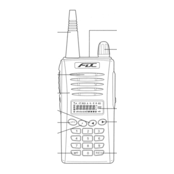
Page 6: Getting Acquainted
GETTING ACQUAINTED LED Indicator Antenna Power switch/ Volume control Speaker Microphone Increase key LCD Screen Decrease key Function key Rev key Keypad lock... - Page 7 PTT Switch Speaker & Mic Jacks Monitor key...
-
Page 8: Lcd Display
LCD DISPLAY The locations of icons used in the LCD DISPLAY are shown in the diagram below, their meaning is explained in the table following. EXPLANTION Signal scan indicator Signal strength indicator Turn speaker on / off Turn sound on / off Reverse frequency High power output Low power output... -
Page 9: Basic Operation
BASIC OPPERATION Installing the Antenna Screw the antenna into the SMA connector on the top of the transceiver by holding the antenna at its base and turning it clockwise until secure. Power switch/Volume control To switch the transceiver ON, turn the knob clockwise until you hear a click, further rotation increases the sound level. -
Page 10: Transmitting
Transmitting To call a station, press and hold the PTT switch, then speak into the microphone using your normal voice. Release the PTT switch to receive. • The transmit indicator light is when transmitting and when receiving a signal. Green Operating modes There are two basic operating modes for this radio VFO/MR mode and Channel Only mode. -
Page 11: Programming With The Keypad
PROGRAMMING WITH THE KEYPAD IN VFO MODE Switch the transceiver ON, then press [ VFO ] key to select either MR (Memory Mode) or VFO (Frequency Mode). • To key in a specific frequency or program a Note: memory channel you must be in VFO mode. F u n c t i o n k e y s : Squelch Press [ F ] + [ 1 ] key sequence to display squelch level, the... -
Page 12: Auto-Scan (F+3)
• Selecting the LOWEST power required for clear Note: communication will decrease the power usage and extend the battery life. Auto-Scan Press [F] + [3] key sequence to start auto-scan of memory channels, scans in both VFO and MR modes. •... -
Page 13: Manual Scan
Manual Scan Use [◄] / [►] keys to scan manually. In VFO mode frequency increments according to preset step amount (see item # 13). In MR mode frequency increments by programmed memory channels. Press PTT switch to exit scan mode. Backlight Press [F] + [4] key sequence to view backlight setting, use [◄] / [►] keys to select desired backlight setting ON / OFF / AUTO. -
Page 14: Auto Lock Keypad (F+6)
Auto Lock Keypad (See item #12 to unlock) Press [F] + [6] key sequence to view the current setting. Use the [◄] / [►] keys to select either AUTO or MANUAL. Press PTT switch to accept selected setting and exit. Auto lock locks keypad after 20 seconds idle time. -
Page 15: Ctcss/Dcs Receive (F+9)
10. CTCSS/DCS Receive For CTCSS coding press [F] + [9] key sequence to view the setting for the current frequency. Use [◄] / [►] keys to select the CTCSS frequency value desired. Press PTT switch to accept selected setting and exit. (See table at end of document for CTCSS values) To use DCS coding Press [F] + [9] + [F] sequence to view the setting for the current frequency. -
Page 16: 12. Lock/Unlock Keypad
To use DCS coding Press [F] + [0] + [F] sequence to view the setting for the current receive frequency. Use [◄] / [►] keys to select the DCS frequency value desired then press ] key to set DCS Normal/Inverse option. Press PTT switch to accept selected settings and exit. -
Page 17: Duplex-Simplex
Press [F] + [REV] key sequence to view settings for currently displayed frequency. Use [◄] / [►] keys to select either “S” simplex operation, or for duplex operation select either “+” for positive offset or “-“for negative offset. Press PTT to accept selected setting and exit. -
Page 18: Memory Channels
MEMORY CHANNELS In MR mode you use programmed memory channels, eliminating the need setup each time. You can store frequencies and settings in up to 99 different memory channels on this transceiver. Programmi ng a memo ry ch annel In the VFO mode Select desired frequency and settings you require, then press the [F] + [VFO] key sequence. -
Page 19: Channel Only Mode
CHANNEL ONLY MODE Chanel only mode is an operating mode where you ONLY use pre-programmed frequencies and settings. It works the same as MR mode in VFO/MR mode. It uses only CHANNELS for simplicity of operation and does not display any frequency information. The CHANNELS are the memory channels programmed in VFO/MR mode. -
Page 20: Deleting Settings
DELETING SETTINGS Deleting a memory channel Select the desired memory channel to delete. Turn the transceiver OFF. Press and hold the [VFO] key turn the transceiver ON. The LCD displays "DEL--?". Press the [VFO] key again to delete the selected channel and exit the delete mode. -
Page 21: Ctcss Table
C T C S S T A B L E 67.0 85.4 107.2 136.5 165.5 186.2 210.7 69.3 88.5 110.9 141.3 167.9 189.9 218.1 71.9 91.5 114.8 146.2 171.3 192.8 225.7 74.4 94.8 118.8 151.4 173.8 196.6 229.1 77.0 97.4 123.0 156.7 177.3 199.5 233.6 79.7 100.0 127.3 159.8 179.9 203.5 241.8 82.5 103.5 131.8 162.2 183.5 206.5 250.3 5 0 G r o u p s o f C T C S S ( H... -
Page 22: Quick Reference
FD-150A / 160A / 450A /460A Quick Reference Mode Select [VFO] (direct-input/channel) TX/RX Freq. Reverse [REV] press & hold Keypad Lock/Unlock press & hold Down Tone* [F][0] CTCSS [F] DCS [VFO] inv.DCS Squelch Level [F][1] RF Output Hi/Low [F][2] hi/low...
Need help?
Do you have a question about the FD-150A and is the answer not in the manual?
Questions and answers