Samsung SVR-1660 User Manual
Digital video recorder
Hide thumbs
Also See for SVR-1660:
- User manual (97 pages) ,
- User manual (104 pages) ,
- Install manual (54 pages)
Table of Contents
Advertisement
Quick Links
Download this manual
See also:
Installation Manual
Advertisement
Table of Contents

Related Manuals for Samsung SVR-1660


Summary of Contents for Samsung SVR-1660
- Page 1 User Manual...
-
Page 2: Product Warranty And Limits Of Responsibility
Introduction Thank you for purchasing the SVR-1660. This is a user manual for SVR-1660. Before product installation and operation, please become thoroughly familiar with this user manual and other manuals referenced by this manual. This user manual and the software and hardware described here are protected by the copyright law. - Page 3 User Manual This product is not for exclusive use of crime prevention but for assistance unit such as a fire or theft. Therefore, we never take any responsibility for the damage from any incident. Various experience and technical is needed for installation of this product and individual installation might cause fire, electric shock, and defect.
-
Page 4: Table Of Contents
User Manual Contents Chapter 1. Safety Cautions ............8 1.1 Symbols displayed for each item ..................8 Chapter 2. Summary ..............11 Features ........................11 Chapter 3. Product Description ..........14 Front part ........................14 Rear Part ........................15 OSD MENU structure ....................17 Function Menu ...................... - Page 5 User Manual 4.10 Application of SPOT monitor .................... 29 Chapter 5. Playback ..............30 Various Playback mode ....................30 5.1.1 Basic Screen Playback (9 division screen) ............30 5.1.2 Various Playback functions ..................30 5.2 SEARCH mode ........................31 5.2.1 Time Search ......................
- Page 6 User Manual 6.8 Monitor Setup ........................50 6.9 Event Setup ........................52 6.9.1 Event ........................... 52 6.9.2 Text ..........................54 6.9.3 D-I/O ..........................55 6.9.4 Event Action ........................ 56 6.9.5 Network ........................57 6.9.6 xDSL..........................58 6.9.7 DDNS .......................... 59 DDNS Registration ........................
- Page 7 User Manual 7.4.10 Audio Use ......................80 7.4.11 Image Channel Close .................... 80 7.5 Playback ..........................81 7.5.1 Screen Division & Channel Change ..............81 7.5.2 Image Recording ....................81 7.5.3 Print........................82 7.5.4 Web Monitor move ....................82 7.5.5 Channel On/Off ......................
-
Page 8: Chapter 1. Safety Cautions
User Manual Chapter 1. Safety Cautions 1.1 Symbols displayed for each item Warning Refers to information users need to know in order to prevent serious injury or death. Before installation Verify the supplied voltage (AC100V~AC240V) before connecting the power supply. Make sure the power supply is off before installation. - Page 9 User Manual Dismantling and cleaning Do not dismantle, repair or modify the product deliberately. Doing so may cause a damage, an electric shock or an injury. Do not use water, thinner or organic solvent for cleaning the product exterior. Doing so may cause a malfunction or an electric shock.
- Page 10 This product should not be mix ed with other commercial wastes for disposal. Samsung Techwin cares for the environment at all product manufacturing stages to preserve the environment, and is taking a number of steps to provide customers with more environment- friendly products.
-
Page 11: Chapter 2. Summary
When it set functions, it can easily setup through operating mouse & button at front. Samsung SVR-1660 are digital image recording devices used to Bank, Apartment, Public offices, and are the independent product that system performance & safety are ensured. -
Page 12: Video Recording
User Manual Video Recording It can record image high quality MPEG-4 real time image into max. 480 frames per second and max. 5 seconds at pre-event. Also, it protects privacy through COVERT (Hiding image) function. High quality MPEG-4 realtime image recording 4 steps recording resolution setup for the control of recording capacity Multi recording function for manual event &... - Page 13 User Manual Basic supply item : Built-in Hard disk Various Copy device support : DVD-R, CD-R, USB memory Refer to the appendix on the back of the manual regarding the type of compatible media Hard disk expansion device(External recording device) : SVS-5E (Option as exclusive device) Network It supports various networks like LAN, xDSL and can operate and manage main functions of...
-
Page 14: Chapter 3. Product Description
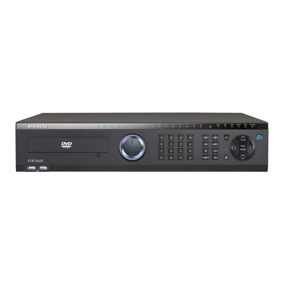
User Manual Chapter 3. Product Description Front part Classification Function DVD-Multi It uses when Copy recorded images through DVD/CD for Copy media. Channel LED It shows the status of image input and event action. JOG can adjust set value in menu and control STEP function. -
Page 15: Rear Part
User Manual MENU Enter into Menu. SEARCH Enter into Search mode. COPY Enter into Copy mode. FUNC Enter into Function mode. ESC button Use this when it step out from Menu or close pop-up window. PLAY/ENTER Enter into Playback mode or select Menu. ◀/REW It moves &... - Page 16 User Manual Input/Output terminal Function name MONITOR BNC connection terminal for Monitor output SPOT BNC connection terminal for Spot monitor out AUDIO IN(RCA) RCA connection terminal for Audio input AUDIO OUT Speaker output terminal ETHERNET Network connection terminal (RJ-45) eSATA Connection terminal for external eSATA HDD or HDD for Copy VGA OUTPUT...
-
Page 17: Osd Menu Structure
User Manual OSD MENU structure Menu structure is same as below picture and for each configuration method per Menu, please, refer to the explanation from chapter 4 to chapter 6. Function Menu Function menu lets mouse to control all of the product function and operation. When using each function, please, click Icon by left button of mouse. -
Page 18: Factory Default Setting
User Manual Factory default setting To make the product factory default setup, execute according to following order. System configuration->System->configuration. If pressing “Enter” button after selecting default configuration, system will be initialized. If window pops up showing the message “Warning, system will be initialized. Factory default”, selects “Yes”... - Page 19 User Manual Current Time Language English Screen Setup Screen Channel Number Title Cam 1 Activity Color Color Enable Brightness Contrast PTZ Home PTZ Idle Time PTZ Port None Address Monitor Monitor Number Monitor Switch to Event Screen Covert Channel All Uncheck User Sequence All Not Set SEQ.
- Page 20 User Manual Pre Event Post Event Schedule Channel Number Schedule Full Time Macro No Rec. Speed 1/0.75fps Quality Resolution Special Time No Rec. Event Recording Event Channel Number Type Sensor Text Macro Standard Speed 8fps Quality Resolution Pre Event Post Event Event Setup Event Sensor...
- Page 21 User Manual Event Action Select Action Action Duration Action Source Full Time, Uncheck All Event Acton Full Time, Disable Special Time Preset Channel Number Preset Sensor1, Not Set System Event System Event Uncheck All Source System Event Uncheck All Method Communication Network Type...
- Page 22 User Manual Serial Serial Number Com1 Device None Interface RS232 Baud Rate 9600 Parity Bit None Stop Bit Data Bit System Setup System Remote Controller ID DVR ID DVR Alias DVR0 Playback Deinterlace Language English Firmware Update >> Load/Save >> Configuration Default >>...
- Page 23 User Manual Day Start 09:00 Day End 18:00 Special Time Zone 1 00:00 – 00:00 Zone 2 00:00 – 00:00 Zone 3 00:00 – 00:00 Zone 4 00:00 – 00:00 Exception Days >> Save Save >> Do not save >>...
-
Page 24: Chapter 4. Monitoring
User Manual Chapter 4. Monitoring If power on to DVR only, analog image of all channels connected to monitor mode appear on screen. This is to utilize all monitoring mode of DVR. Basic Screen view If Power connects, DVR is on automatically. All LED is On/Off in order and is booting. -
Page 25: Basic System Mode
User Manual Sequence. 4.4.1 Basic System mode If it uses [AUTO] button , it can setup sequence channels to view automatically. Press [MENU] button to set up sequence period. When using mouse, press menu button at Function menu. Move to “Screen Setup” from OSD menu. Move to “Monitor”... -
Page 26: Event Screen View
User Manual 1. User mode can define maximum 16 users. 2. Above example picture is defined 6 sequences and shows in order to Single screen (1) All screen(9DIV) 4 division screen(4A) Single screen(5) Single screen (6) 4 division screen (4B). Event Screen view In case of Event, it can sets relevant screen to Pop-up automatically. -
Page 27: Enlarged Screen View
User Manual Pressing any button and returns to Previous screen by pressing any button. Enlarged Screen view When pressing [FUNC] at single image full screen mode and select [D-ZOOM] , it can view enlarged image by selecting +button and Enter button or click left mouse button. In case of selecting [D-ZOOM] , default of enlarged screen location is the center. -
Page 28: Zoom/Focus Control
User Manual 4.8.2 Zoom/Focus Control This menu used to utilize Zoom & Focus functions from real time monitoring mode. Select Zoom/Focus from PTZ mode. It utilizes for Zoom & Focus functions through direction key at front part or mouse wheel. 4.8.3 Load Preset application This menu is used when it moves to Preset location from real time monitoring mode. -
Page 29: Application Of Spot Monitor
User Manual Load mode is released through input of relevant Password. 4.10 Application of SPOT monitor Basic monitor is used for all functions of DVR like Menu setup, Live images (16 divisions) and Playback, and Spot monitor can be used for two functions of Single channel live image and Event pop-up image. -
Page 30: Chapter 5. Playback
User Manual Chapter 5. Playback Various Playback mode 5.1.1 Basic Screen Playback (9 division screen) Press [PLAY] button from monitoring mode or click Play button from Function menu using mouse. If it press [PLAY, >] button and [FWD] button for changing speed, it playback image forwarding in 1x speed set first. -
Page 31: Search Mode
User Manual At Live screen, it Reverse Play recording image from the time of last recorded area by pressing REW button. It also changes the speed by pressing at Function menu. STEP FORWARD : While Play, it plays forward by a frame of image if it press [FWD] button at the stage of pressing Pause button. -
Page 32: Calendar Search
User Manual : It indicates Date & Time starts recording first. Start-REC Time End-REC Time : It indicates Date & Time of recording the most recent. Search Time : Select Date & Time wants to search from starting time to present time of Recording. -
Page 33: Thumbnail Search
User Manual Start-REC Time : It indicates Date & Time starts recording first. End-REC Time : It indicates Date & Time of recording the most recent. : Input starting date & time to search. Move the parts to setup using Search Start Time direction button and press Enter to change the value. -
Page 34: Copy
User Manual : It divides into regular base for searching and indicates result. It can Interval change through up/down button or mouse wheel. Image view : If user pushes “Search” button, 16 images per second will be displayed based on the start time. If user wants to return to search mode, please use “Func”... -
Page 35: Re4
User Manual select disk. Start : Start COPY. Press Start button through Enter button or click left mouse button. FAT32 Format : Format USB disk or HDD to FAT32. When DVD Copy, it does not use. When using media, it executes format first to use by selecting FAT32 Format button and press Enter button or left mouse click. - Page 36 User Manual Type : Select RE4 using up/down button or mouse wheel. : Press Enter from Channel part to pop-up channel selection window or Channel List pop up Channel List using mouse wheel. Selecting : Among 16 channels, it can select a part or all channels. Select the Channel channel from Channel list and press Enter button or click left mouse button.
-
Page 37: Avi
User Manual 5.3.3 AVI It is to Copy a part of one channel selected to USB memory or HDD. Type : Select AVI using up/down button or mouse wheel. : Select the channel wants to Copy using up/down button or mouse Channel wheel. -
Page 38: Chapter 6. Configuration
User Manual Chapter 6. Configuration 6.1 Record Setup There are 4 different modes to DVR recording, and it can see Setup relation like the following structure of picture. It explains Recording type briefly. Refer to each item below for the detailed setup relate to Recording. 6.2 Time Setup (System Time) Time setup of production is required before Record Setup. -
Page 39: Method Of Time Setup
User Manual Dublin”. 6.2.1 Method of Time Setup When it changes the time during the condition of recording already, it recommends Copy for important data before the time change because it changes the time of image recorded. Press [MENU] at front or Menu button at Function. -
Page 40: Camera Setup
User Manual Apply Date/Time To apply Date/Time set value must press “Apply Date/Time” button. It indicates dialog box as follows by pressing business. Except “Date/Time” setup, other setups are saved automatically when it is closed completely, but “Date/Time” setup does not saved automatically because it can affect to HDD recording file system critically. -
Page 41: Method Of Camera Setup
User Manual 6.3.1 Method of Camera Setup It moves to “Cam#1 ~ Cam#9” under “Camera” of Screen Setup using direction key or mouse wheel after pressing [MENU] button.. 6.3.1.1 Title Set up Camera Name. Relevant character setup menu appears if it press [ENTER] or mouse click. Character input window appears when it inputs characters. -
Page 42: Quick Record Setup (Quick Setup)
User Manual left/right button or mouse wheel. 6.3.1.6 PTZ It sets PTZ Home, Idle Time, Port, Address relate to PTZ device. 6.3.1.6.1 PTZ Home / PTZ Idle Time This is menu to setup camera supports PTZ (Pan/Tilt/Zoom), and it moves to PTZ assigned when there is no movement during specified time. -
Page 43: Method Of Quick Record Setup
User Manual 6.4.1 Method of Quick Record Setup Select ‘Quick Setup’. Recording Speed/Quality There are all 5 setup conditions. Default set value is ‘No Rec.’ that means does not record. No Rec. / Low / Standard / High / Custom Except “Custom”, setup condition sets to synchronies ‘Speed (fps)’, ‘Quality’, ‘Resolution’... -
Page 44: Setup By Channel
User Manual 6.5.2 Setup by Channel It can set Time Schedule, Macro differently by each channel. It sets 1~8CH to Weekday day, Low, and can set 9~16 to Full Time, High Recording Speed/Quality There are total 5 setup conditions. (No Rec./Low/Standard/High/Custom). “Custom”... -
Page 45: Event Recording
User Manual setup. 6.6 Event Recording This menu can set recording by event when Event occurs. Event recording can record by ‘Sensor’, ‘Motion Detection’ and ‘Text’. To do Event recording must set All or Setup by Channel from ‘Schedule Recording’ in advance. After setup recondition condition, it must set “Event Recording”... -
Page 46: Text Setup
User Manual of each channel Motion Detection It sets 12 different sensitivities; low, 1, 2, 3, 4, 5, 6, 7, 8, 9, 10, High 6.6.1.3 Text Setup This menu is for configuring input text information and user set "Event Configuration" value in OSD menu by Text. -
Page 47: All Event Record Setup
User Manual 6.6.2 All Event Record Setup This is setup all analog channels in identical condition. Sensor/MD/Text It sets whether it synchronize with Sensor/MD/Text event. Pairing means synchronizing 1:1 between channel and Sensor/MD. 6.6.2.1 Setup by Channel Event Source Through Event Source can select 9 Sensors, 1 MD and a Text input. Selecting Sensor selects box of relevant number. -
Page 48: Manual Recording Setup
User Manual In the condition except “Custom”, “Speed (fps)” and “Quality” are synchronized automatically. Pre Event (sec) It can set max. 5 seconds. Post Event (sec) It can set max. 60 seconds. 6.6.3 Manual Recording Setup When user presses [REC] button at front part, this menu can setup recording condition of image. If manual recording starts, existing recording setup set is ignored and it records image in the value set from Recording Setup>>... -
Page 49: Audio & Other Setup (Audio Recording)
User Manual It means the time records before user press [REC] button. It can set max. 5 seconds. Post Event (sec) It means the time record after user press [Rec] button. It can set max. 60 seconds. 6.7 Audio & Other Setup (Audio Recording) Through this menu can set recording of Audio setup &... -
Page 50: Audio Mix
User Manual 6.7.2 Audio Mix Select Audio to use from Live image. In case of All setup, all input audio is out in mixed. And when selecting specific audio, it is out bony selected channel unconditionally whatever any channel is selected. 6.7.3 Record No Video It sets whether it records the input image that has fault or the channel delete image intentionally or not. - Page 51 User Manual Monitor & Spot Monitor The entire function of DVR is available for monitor and spot monitor can use single channel monitor and event pop up. Switch to Event Screen (sec) In case of Event, it sets to Pop-up relevant screen automatically. Pop-up duration can set from 2~10 seconds and select among Keep.
-
Page 52: Event Setup
User Manual mode, or it can select the channel through [Enter] button or mouse wheel after window open and the channel select using mouse wheel. VGA Mode It can select among 3 resolutions of VGA output, 800 x 600, 1024 x 768 and 1280 x 1024. Info Level Display information configures what kind of information will be shown to live image and playback image. - Page 53 User Manual It can set channel to All or 1~9CH. - Sensitivity In case of Sensitivity, it can set sensitivity per each channel Off, Lowest, Low, Middle, High, and Highest. - Area Area sets detecting area when MD set. In case of All set, it can select Set All, Clear All. In case of setup by each channel, it can set to Set All, Clear All, and Select Area.
-
Page 54: Text
User Manual 6.9.2 Text Recording It can On/Off recording in regard to Text input. Sync Text With It selects Text data and synchronization channel. Seek Header Various data types come from external device (Access Control, POS, and ATM etc). Like Star Finger 007, it does not need protocol that is registered already. -
Page 55: D-I/O
User Manual data. Lines It defines a data consists of how many line. In case of External device, it must consult with seller before installation because it may be not recognized according to feature. 6.9.3 D-I/O D-I/O is Port able to use digital Input & Output simultaneously. It has 12 Digital Input & Output. D-I/O Channel &... -
Page 56: Event Action
User Manual 6.9.4 Event Action Event Action sets workable Action according to Event Input. Select Action Select Action can select R1~4, Buzzer, E-Mail. Action Duration Action Duration operates when Relay works and keeps as long as the time set, and also Buzzer keeps in same way. -
Page 57: Network
User Manual Event Action in Special Time It sets whether it operates Event Action in Special Time or not. 6.9.5 Network When DVR connects to network, this is menu to setup relevant network data. Type It sets up network line type (Ethernet/xDSL) connects to DVR. When it is connected Exclusive line or cable model or LAN of DVR, it sets to ‘Ethernet’. -
Page 58: Xdsl
User Manual IP Addr IP Address is used when communicating DVR & CMS and is used to connect from Webviewer to DVR. But it is available when Net Mask and Gateway are set. Net Mask Net Mask assigns the range able to input IP Address and same range of IP make possible to communicate. -
Page 59: Ddns
User Manual User ID/Password If DVR is connected to xDSL, it must set ID & Password. Status It indicates the condition of DVR connection. 6.9.7 DDNS It DVR is connected to cable model or xDSL modem, IP address is changed whenever it tries to connect to ISP. - Page 60 User Manual - Agreement the general terms and conditions - SIGN UP page: check ID availability 2) The product registration is possible after sign up. - Sign in at iPOLiS website...
- Page 61 User Manual - Product List (If you didn’t register products, there are no list) - Product Registration (Check ID availability) - Check the registration at product list 3) Set-up DDNS information.
- Page 62 User Manual SVR-1660 can be set up under the network screen in the order as listed in the menu. If you press the menu button and select the network, you will see the screen as shown in the diagram below.
-
Page 63: Ntp
User Manual To register fixed IP to DDNS refer to following explanation for setup. Interval For the continuous registry, it sets register period from ‘WRS Interval’. According to setup value, fixed IP address renews its data to DDNS server regularly. If user sets register period to ‘0’ or it does not transmit any data of DVR for 2 days, its data is deleted from DDNS. -
Page 64: Serial
User Manual Sync With NTP It cans NTP function On/Off. NTP Mode It sets whether it operates NTP mode of DVR to Client, Server or Both. NTP Server Loc. When NTP Mode is set to Client, it is enabling. It sets whether NTP server is on Local Network or internet (Public). -
Page 65: System Setup
User Manual Serial port Select the port to control by connecting with the unit Device Set external device connected. Interface This menu is to setup using which interface. It fixed COM1, COM3 to RS-232C, and COM2 to RS-422/485, COM4 to RS-485. Baud rate/Parity/Stop (bit)/Data (bit) Configure the value same as the set value of external unit. - Page 66 User Manual Remote Controller ID Max. 16 remote controllers ID are selectable, and it can control max. 16 DVR It can register Remote controller as following order. Direct Remote controller to DVR. Press ID button that suits to Remote Control ID set. If Remote controller ID is identical to DVR ID, DVR buzzers.
-
Page 67: Disk Setup
User Manual Load Configuration It sets DVR setup value stored in USB memory by transmitting to DVR. Save Configuration Save preset setup status of DVR to USB device. Default It used when it sets existing set value to first factory value to ship. To create first value press “Default”. - Page 68 User Manual 30days among 30days. It can set from 1day till 31days. Disk Manager Disk Manager is to manage internal or external HDD using. It manages the state indication of HDD, Bad Block, Size, Add, Remove etc. Disk Status It can view HDD temperature, state of HDD installed in System. Type : It indicates location of disk.
-
Page 69: Security
User Manual - It pops up NOTICE window and shows next message using [Enter] button or rolling mouse wheel at the condition of Enabled Yes. - “Disk will be removed” - If select Yes, “Recording disk removed” is appeared and changed to Enabled No. - HDD is not used. -
Page 70: Special Time
User Manual Weekday Start/End Among Monday to Sunday, it sets Weekday time period. The other part unset is under Weekend time period. Day Start/End It sets Day time period using up/down direction key. Unset parts means Night time period. 6.10.5 Special Time Special Time is able to four setups. -
Page 71: Exit
User Manual Use when it sets of irregular exceptional time. It can set max. 30 irregular exceptional times and set Start Time, Duration, Profile. Start Date & Time : It indicates stat date & time of exceptional zone. : It sets time apply Profile from exceptional time set. Duration Profile : Profile is to set simultaneous recording with Schedule setup of... - Page 72 User Manual Save This is menu to save the state of setup at other menu and exit to live screen, it can select into Set or No Set. Select “Yes” when it saves the setting and exit, or select “No” when it does not save setting and exit.
-
Page 73: Chapter 7. Web Viewer
User Manual Chapter 7. Web Viewer WebViewer is web program loaded into product that can view image recorded or monitoring image of product in real-time through web browser in PC remotely able to use Internet.. Structure of Web Viewer is divided into Monitor which can monitor image in real-time with Login page, and Playback which can playback recorded image. -
Page 74: Connection User Setup
User Manual 7.2 Connection User setup It must input user ID & Password set into Configuration Tool program to log in WebViewer. It can use ID & Password of an administrator and 10 general users. It is able to change administrator and user’s ID for security. Cancel by check ‘Use’ of user’s account disusing. -
Page 75: Usable Browser
User Manual Check ‘Hard’ in user account at authority setup of Configuration Tool to use Playback page. Also, it checks Check box and apply so that user ID who sets like ‘Microphone’, ‘PTZ’, ‘Relay’ can use. When it shows 1CH image only, check the rest channel and uncheck the rest channels & functions. -
Page 76: Screen Division & Image Location Change
User Manual Let’s study introduction and functions about each part term of Monitor page. 7.4.1 Screen division & Image location change It shows to 9 divisions, 16 divisions, or 32 divisions according to channel number of product when connect to Monitor page. It can change to 1, 4, 9 ,13, 16 divisions by click number of upper page. -
Page 77: Channel On/Off
User Manual 7.4.3 Channel On/Off Channel On/Off button is located on left page. It can On or Off by click the channel wants, and default is On. Above picture is Off state about 9~16CH. When Channel is Off, it changes to grey color and image is not visible and is changed to black. -
Page 78: Microphone Use
User Manual 7.4.6 Microphone use It can microphone On or Off and Default is Off. In case of click button, projecting button changes to Blue and microphone is available. Inactivated Mic button is the case that it does not support at relevant product. 7.4.7 Event Data It shows Event data happens in real-time at bottom of monitoring page. -
Page 79: Ptz Use
User Manual Among image recording, if it closes recording by click “Rec Stop” of right mouse again and open dialog box to record file recording, user saves to temporary directory with naming to the file. Recorded file is saved to “*.re4” file, and re4 file is able to playback through CMS Playback program Mini Player program. -
Page 80: Audio Use
User Manual Pan/Tilt works faster. Zoom, Focus Control If it move mouse to left, right edges, it shows slide bar for Zoom, Focus. A unit that is possible to Area Zoom has Zoom Zero work button. Using left side slide bar of image can Zoom In/Out, and left side slide bar can control Focus. -
Page 81: Playback
User Manual To reconnect the channel disconnected clicks channel button that is turned Off to reconnect relevant channel. 7.5 Playback This page is to playback the image recorded, and user who has offered ‘HDD’ authority at administrator account or use account can use this. Playback consists of 9 division screen can playback using Search through calendar by recording period or Move period button. -
Page 82: Print
User Manual Select channel want to record by mouse and click ‘Save’ button. Save Image dialog box comes, and it can select input message, Name, Date, Event data. Dialog box asks location to save if press ‘OK’, and it opens dialog box and can save to bmp format file. -
Page 83: Calendar Search
User Manual It indicates total size recorded to HDD and free size, and it indicates starting date & last date of recording. Also it shows indication in percentage about HDD capacity. 7.5.7 Calendar Search Recorded date is activated to Black, and unrecorded date into Grey. If it selects date and time wants to check the image recorded and press button, it playback image of relevant date &... -
Page 84: Compatible Hdd List
User Manual Compatible HDD List Seagate Technology Western Digital Capacity Model Capacity Model 750GB ST3750840SCE 750GB WD7500AVCS 500GB ST3500830SCE 500GB WD5000AVJS 250GB ST3250820SCE 250GB WD2500AVJS Compatible Media List DVD-R manufacture CD-R manufacture Mitsubishi(Exhortation 16X) Mitsubishi(Exhortation 16X) TDK(Exhortation 16X) TDK(Exhortation 16X) Imation(Exhortation 16X) Imation(Exhortation 16X) Sony(Exhortation 16X) - Page 85 User Manual Multi Screen 1, 4, 10,16 Simultaneous Live Display/Playback/Record, Multiplex Function SNM Monitoring/Playback Camera Title 22 Characters per Channel Motion Detection 22x15 (NTSC)/ 22x18 (PAL) grid Automatic E-mail, Internal Buzzer, Relay-out, Pop-up Event Notification Screen, Network Event Internal 250GB basic(4 SATA HDD install possible) External 2 e-SATA(SVS-5E) DVD Writer (CD-R 700MB Media, DVD-R 4.7G Media),...
-
Page 86: Trouble Shooting
User Manual Trouble Shooting 1. No DVR booting Check Power Check Power Cord 2. No Image on Monitor Check monitor power Check monitor & cable condition of DVR Check monitor cable port Check whether DVR power is On 3. No image of some channel Check Camera power Check Camera image input Check DVR input port... - Page 87 User Manual Check Remote control ID Check specification of Remote control operation 8. No operation of front button Check DVR power Check status of Screen Lock 9. No Networking Check whether network cable is connected properly Check DVR IP Check PC IP Ping Test 10.
- Page 88 User Manual Dimensions...
- Page 89 User Manual...
Need help?
Do you have a question about the SVR-1660 and is the answer not in the manual?
Questions and answers