
Related Manuals for ZyXEL Communications ZyWall USG 50-H Series


Summary of Contents for ZyXEL Communications ZyWall USG 50-H Series
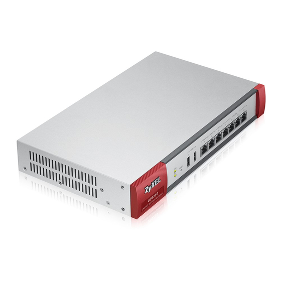
- Page 1 ZyWALL USG 50-H Series Unified Security Gateway User’s Guide Version 2.16 6/2009 Edition 1 DEFAULT LOGIN Port LAN/DMZ 1 IP Address https://192.168.1.1 User Name admin Password 1234 www.zyxel.com...
-
Page 3: About This User's Guide
About This User's Guide About This User's Guide Intended Audience This manual is intended for people who want to want to configure the ZyWALL using the web configurator. How To Use This Guide • Read Chapter 1 on page 31 chapter for an overview of features available on the ZyWALL. - Page 4 Help us help you. Send all User Guide-related comments, questions or suggestions for improvement to the following address, or use e-mail instead. Thank you! The Technical Writing Team, ZyXEL Communications Corp., 6 Innovation Road II, Science-Based Industrial Park, Hsinchu, 300, Taiwan.
- Page 5 About This User's Guide Customer Support Should problems arise that cannot be solved by the methods listed above, you should contact your vendor. If you cannot contact your vendor, then contact a ZyXEL office for the region in which you bought the device. See http://www.zyxel.com/web/contact_us.php for contact information.
-
Page 6: Document Conventions
Document Conventions Document Conventions Warnings and Notes These are how warnings and notes are shown in this User’s Guide. Warnings tell you about things that could harm you or your device. Notes tell you other important information (for example, other things you may need to configure or helpful tips) or recommendations. - Page 7 Document Conventions Icons Used in Figures Figures in this User’s Guide may use the following generic icons. The ZyWALL icon is not an exact representation of your device. ZyWALL Computer Notebook computer Server Firewall Telephone Switch Router Printer ZyWALL USG 50-H User’s Guide...
-
Page 8: Safety Warnings
Safety Warnings Safety Warnings For your safety, be sure to read and follow all warning notices and instructions. • Do NOT use this product near water, for example, in a wet basement or near a swimming pool. • Do NOT expose your device to dampness, dust or corrosive liquids. •... - Page 9 Safety Warnings Your product is marked with this symbol, which is known as the WEEE mark. WEEE stands for Waste Electronics and Electrical Equipment. It means that used electrical and electronic products should not be mixed with general waste. Used electrical and electronic equipment should be treated separately.
- Page 10 Safety Warnings ZyWALL USG 50-H User’s Guide...
-
Page 11: Table Of Contents
Contents Overview Contents Overview Getting Started ........................29 Introducing the ZyWALL ......................31 Features and Applications ......................35 Web Configurator ........................41 Wizard Setup ..........................49 Configuration Basics ........................79 Tutorials ............................. 93 Status ............................131 Network ..........................145 Interface ........................... 147 Trunks ............................ - Page 12 Contents Overview Anti-X ............................ 421 ADP ............................423 Objects ..........................441 User/Group ..........................443 Addresses ..........................457 Services ........................... 463 Schedules ..........................469 AAA Server ..........................475 Authentication Method ......................485 Certificates ..........................489 SSL Application ........................507 System ..........................511 System ...........................
-
Page 13: Table Of Contents
Table of Contents Table of Contents About This User's Guide ......................3 Document Conventions......................6 Safety Warnings........................8 Contents Overview ......................... 11 Table of Contents........................13 Part I: Getting Started ................29 Chapter 1 Introducing the ZyWALL ......................31 1.1 Overview and Key Default Settings ..................31 1.2 Front Panel LEDs ........................ - Page 14 Table of Contents 3.3.1 Title Bar ........................43 3.3.2 Navigation Panel ......................44 3.3.3 Main Window ......................47 3.3.4 Message Bar ......................47 Chapter 4 Wizard Setup ........................... 49 4.1 Wizard Setup Overview ....................... 49 4.2 Installation Setup, One ISP ....................50 4.3 Step 1 Internet Access ......................
- Page 15 Table of Contents 5.4.6 L2TP VPN ........................85 5.4.7 Zones ......................... 85 5.4.8 DDNS ......................... 85 5.4.9 Policy Routes ......................85 5.4.10 Static Routes ......................86 5.4.11 Firewall ........................86 5.4.12 Application Patrol ..................... 87 5.4.13 ADP .......................... 88 5.4.14 Virtual Server (Port Forwarding) ................88 5.4.15 HTTP Redirect ......................
- Page 16 Table of Contents 6.8 How to Configure Service Control ..................122 6.8.1 How to Allow HTTPS Administrator Access Only From the LAN ......122 6.9 How to Allow Incoming H.323 Peer-to-peer Calls ............. 124 6.9.1 How to Turn On the ALG ..................125 6.9.2 How to Set Up a Virtual Server Policy For H.323 .............
- Page 17 Table of Contents 8.6 The PPP Interfaces Screen ....................166 8.6.1 PPP Interface Edit Screen ..................167 8.7 Cellular Configuration Screen (3G) ................... 171 8.7.1 Cellular Add/Edit Screen ..................173 8.8 Cellular Status Screen ....................... 176 8.9 Tunnel Interface Screen ....................179 8.9.1 Configuring the Tunnel Screen .................
- Page 18 Table of Contents 10.3.1 Static Route Add/Edit Screen ................. 233 10.4 Policy Routing Technical Reference ................234 Chapter 11 Routing Protocols......................... 237 11.1 Routing Protocols Overview ..................... 237 11.1.1 What You Can Do in the RIP and OSPF Screens ..........237 11.1.2 What You Need to Know About Routing Protocols ..........
- Page 19 Table of Contents 15.1.1 What You Can Do in the HTTP Redirect Screens ..........269 15.1.2 What You Need to Know About HTTP Redirect ............. 270 15.2 The HTTP Redirect Screen ..................... 270 15.2.1 The HTTP Redirect Edit Screen ................271 Chapter 16 ALG ............................
- Page 20 Table of Contents Part IV: VPN ..................305 Chapter 19 IPSec VPN..........................307 19.1 IPSec VPN Overview ....................... 307 19.1.1 What You Can Do in the IPSec VPN Screens ............307 19.1.2 What You Need to Know About IPSec VPN ............308 19.1.3 Before You Begin ....................
- Page 21 Table of Contents Chapter 23 ZyWALL SecuExtender......................359 23.1 The ZyWALL SecuExtender Icon ..................359 23.2 Statistics .......................... 359 23.3 View Log .......................... 361 23.4 Suspend and Resume the Connection ................361 23.5 Stop the Connection ......................361 23.6 Uninstalling the ZyWALL SecuExtender ................361 Chapter 24 L2TP VPN..........................
- Page 22 Table of Contents 26.4.1 The Other Applications Add/Edit Screen ..............414 26.5 Application Patrol Statistics ..................... 417 26.5.1 Application Patrol Statistics: General Setup ............417 26.5.2 Application Patrol Statistics: Bandwidth Statistics ..........417 26.5.3 Application Patrol Statistics: Protocol Statistics ............. 418 Part VI: Anti-X..................
- Page 23 Table of Contents 28.5 User /Group Technical Reference ................... 455 Chapter 29 Addresses..........................457 29.1 Overview .......................... 457 29.1.1 What You Can Do Using The Addresses Screens ..........457 29.1.2 What You Need To Know About Addresses /Groups ..........457 29.2 Address Summary Screen ....................
- Page 24 Table of Contents 32.5 Configuring a Group of RADIUS Servers ............... 482 32.5.1 Adding a RADIUS Server Member ................. 482 Chapter 33 Authentication Method ......................485 33.1 Overview .......................... 485 33.1.1 What You Can Do Using The Auth. Method Screens ..........485 33.1.2 Before You Begin ....................
- Page 25 Table of Contents 36.1.1 What You Can Do In The System Screens ............513 36.2 Host Name ........................514 36.3 Date and Time ........................ 514 36.3.1 Pre-defined NTP Time Servers List ................ 516 36.3.2 Time Server Synchronization ................. 517 36.4 Console Port Speed ......................518 36.5 DNS Overview .........................
- Page 26 Table of Contents Chapter 37 File Manager ......................... 553 37.1 Overview .......................... 553 37.1.1 What You Can Do in the File Manager Screens ............. 553 37.1.2 What you Need to Know About the File Manager ..........553 37.2 The Configuration File Screen ..................555 37.3 The Firmware Package Screen ..................
- Page 27 Table of Contents Chapter 43 Product Specifications ......................591 43.1 General Specifications ..................... 591 43.2 Power Adaptor Specifications ..................595 Part X: Appendices and Index ............597 Appendix A Log Descriptions ....................599 Appendix B Common Services..................... 637 Appendix C Importing Certificates..................641 Appendix D Wireless LANs ....................
- Page 28 Table of Contents ZyWALL USG 50-H User’s Guide...
-
Page 29: Getting Started
Getting Started Introducing the ZyWALL (31) Features and Applications (35) Web Configurator (41) Configuration Basics (79) Tutorials (93) Status (131) -
Page 31: Introducing The Zywall
H A P T E R Introducing the ZyWALL This chapter gives an overview of the ZyWALL. It explains the front panel ports, LEDs, introduces the management methods, and lists different ways to start or stop the ZyWALL. 1.1 Overview and Key Default Settings The ZyWALL is a comprehensive security device designed for Small and Medium Businesses (SMB) and branch offices. -
Page 32: Management Overview
Chapter 1 Introducing the ZyWALL The following table describes the LEDs. Table 1 Front Panel LEDs COLOR STATUS DESCRIPTION The ZyWALL is turned off. Green The ZyWALL is turned on. There is a hardware component failure. Shut down the device, wait for a few minutes and then restart the device (see Section 1.4 on page 33). -
Page 33: Starting And Stopping The Zywall
Chapter 1 Introducing the ZyWALL Console Port You can use the console port to manage the ZyWALL. You have to use CLI commands, which are explained in the Command Reference Guide. The default settings for the console port are as follows. Table 2 Managing the ZyWALL: Console Port SETTING VALUE... - Page 34 Chapter 1 Introducing the ZyWALL ZyWALL USG 50-H User’s Guide...
-
Page 35: Features And Applications
H A P T E R Features and Applications This chapter introduces the main features and applications of the ZyWALL. 2.1 Features The ZyWALL’s security features include VPN, firewall, ADP (Anomaly Detection and Protection), and certificates. It also provides bandwidth management, NAT, port forwarding, policy routing, DHCP server and many other powerful features. -
Page 36: Packet Flow
Chapter 2 Features and Applications The ZyWALL’s ADP protects against network-based intrusions. See Section 27.3.4 on page Section 27.3.5 on page 430 for more on the kinds of attacks that the ZyWALL can protect against. You can also create your own custom ADP rules. Bandwidth Management Bandwidth management allows you to allocate network resources according to defined policies. -
Page 37: Interface To Interface (Through Zywall)
Chapter 2 Features and Applications 2.2.1 Interface to Interface (Through ZyWALL) Ethernet -> VLAN -> Encap -> ALG -> DNAT-> Routing -> FW -> AP-> SNAT -> BWM - > Encap -> VLAN -> Ethernet 2.2.2 Interface to Interface (To/From ZyWALL) To: Ethernet ->... -
Page 38: Ssl Vpn Network Access
Chapter 2 Features and Applications Figure 3 Applications: VPN Connectivity 2.3.2 SSL VPN Network Access You can configure the ZyWALL to provide SSL VPN network access to remote users. The ZyWALL provides what is known as full tunnel mode SSL VPN network access. In full tunnel mode, a virtual connection is created for remote users with private IP addresses in the same subnet as the local network. -
Page 39: User-Aware Access Control
Chapter 2 Features and Applications 2.3.3 User-Aware Access Control Set up security policies that restrict access to sensitive information and shared resources based on the user who is trying to access it. Figure 5 Applications: User-Aware Access Control 2.3.4 Multiple WAN Interfaces Set up multiple connections to the Internet on the same port, or set up multiple connections on different ports. - Page 40 Chapter 2 Features and Applications ZyWALL USG 50-H User’s Guide...
-
Page 41: Web Configurator
H A P T E R Web Configurator The ZyWALL web configurator allows easy ZyWALL setup and management using an Internet browser. 3.1 Web Configurator Requirements In order to use the web configurator, you must • Use Internet Explorer 6.0 or later, Netscape Navigator 7.2 or later, or Firefox 1.0.7 or later •... - Page 42 Chapter 3 Web Configurator Figure 7 Login Screen 3 Type the user name (default: “admin”) and password (default: “1234”). 4 Click Login. If you logged in using the default user name and password, the Update Admin Info screen (Figure 8 on page 42) appears.
-
Page 43: Web Configurator Main Screen
Chapter 3 Web Configurator Figure 9 Main Screen 3.3 Web Configurator Main Screen As illustrated in Figure 9 on page 43, the main screen is divided into these parts: • A - title bar • B - navigation panel • C - main window •... -
Page 44: Navigation Panel
Chapter 3 Web Configurator The icons provide the following functions. Table 5 Title Bar: Web Configurator Icons ICON DESCRIPTION Help: Click this icon to open the help page for the current screen. Wizards: Click this icon to open one of the web configurator wizards. See Chapter 4 on page 49 for more information. - Page 45 Chapter 3 Web Configurator Table 6 Navigation Panel Summary (continued) LINK FUNCTION DDNS Profile Use this screen to define and manage the ZyWALL’s DDNS domain names. Status Use this screen to view the status of the ZyWALL’s DDNS domain names. Virtual Use this screen to set up and manage port forwarding rules.
- Page 46 Chapter 3 Web Configurator Table 6 Navigation Panel Summary (continued) LINK FUNCTION User/Group User Use this screen to create and manage users. Group Use this screen to create and manage groups of users. Setting Use this screen to manage default settings for all users, general settings for user sessions, and rules to force user authentication.
-
Page 47: Main Window
Chapter 3 Web Configurator Table 6 Navigation Panel Summary (continued) LINK FUNCTION File Manager Configuration File Use this screen to manage and upload configuration files for the ZyWALL. Firmware Use this screen to look at the current firmware version and to upload Package firmware. - Page 48 Chapter 3 Web Configurator Figure 11 Warning Messages Click Refresh Now to update the screen. Close the popup window when you are done with it. Click Clear Warning Messages to remove the current warning messages from the window. 3.3.4.2 CLI Messages Click CLI to look at the CLI commands sent by the web configurator.
-
Page 49: Wizard Setup
H A P T E R Wizard Setup 4.1 Wizard Setup Overview The web configurator's setup wizards help you configure initial configuration (Internet) and VPN connection settings. This chapter provides information on configuring the Wizard setup screens in the web configurator. See the feature-specific chapters in this User’s Guide for background information. -
Page 50: Installation Setup, One Isp
Chapter 4 Wizard Setup Use VPN SETUP to configure a VPN connection. See Section 4.6 on page Figure 13 Wizard Setup Welcome 4.2 Installation Setup, One ISP The wizard screens vary depending on what encapsulation type you use. Refer to information provided by your ISP to know what to enter in each field. -
Page 51: Step 1 Internet Access
Chapter 4 Wizard Setup Figure 14 Internet Access: Step 1 The following table describes the labels in this screen. Table 7 Internet Access: Step 1 LABEL DESCRIPTION ISP Parameters Encapsulation Choose the Ethernet option when the WAN port is used as a regular Ethernet. Otherwise, choose PPPoE or PPTP for a dial-up connection according to the information from your ISP. -
Page 52: Ethernet: Auto Ip Address Assignment
Chapter 4 Wizard Setup 4.3.1 Ethernet: Auto IP Address Assignment If you select Auto as the IP Address Assignment in the previous screen, the following screen displays. Click Next to apply the configuration settings. Figure 15 Ethernet Encapsulation: Auto: Finish You have set up your ZyWALL to access the Internet. -
Page 53: Step 2 Internet Access Ethernet
Chapter 4 Wizard Setup The following table describes the labels in this screen. Table 8 Ethernet Encapsulation: Static LABEL DESCRIPTION ISP Parameters Encapsulation This displays the type of Internet connection you are configuring. WAN IP Address Assignments WAN Interface This displays the identity of the interface you configure to connect with your ISP. Zone This field displays to which security zone this interface and Internet connection will belong. -
Page 54: Pppoe: Auto Ip Address Assignment
Chapter 4 Wizard Setup Figure 17 Ethernet Encapsulation: Static: Finish You have set up your ZyWALL to access the Internet. Click Close to exit the wizard. 4.3.4 PPPoE: Auto IP Address Assignment If you select Auto as the IP Address Assignment in the previous screen, the following screen displays after you click Next. -
Page 55: Pppoe: Static Ip Address Assignment
Chapter 4 Wizard Setup Table 9 PPPoE Encapsulation: Auto (continued) LABEL DESCRIPTION Service Name Type the PPPoE service name given to you by your ISP. PPPoE uses a service name to identify and reach the PPPoE server. You can use alphanumeric and - characters, and it can be up to 64 characters long. - Page 56 Chapter 4 Wizard Setup Figure 20 PPPoE Encapsulation: Static The following table describes the labels in this screen. Table 10 PPPoE Encapsulation: Static LABEL DESCRIPTION ISP Parameters Encapsulation This displays the type of Internet connection you are configuring. Service Name Type the PPPoE service name given to you by your ISP.
-
Page 57: Step 2 Internet Access Pppoe
Chapter 4 Wizard Setup Table 10 PPPoE Encapsulation: Static (continued) LABEL DESCRIPTION First DNS Server Enter the DNS server's IP address(es) in the field(s) to the right. Second DNS Leave the field as 0.0.0.0 if you do not want to configure DNS servers. If you do not Server configure a DNS server, you must know the IP address of a machine in order to access it. -
Page 58: Pptp: Auto Ip Address Assignment
Chapter 4 Wizard Setup Figure 21 PPPoE Encapsulation: Static: Finish You have set up your ZyWALL to access the Internet. Click Close to exit the wizard. 4.3.7 PPTP: Auto IP Address Assignment If you select Auto as the IP Address Assignment in the previous screen, the following screen displays. - Page 59 Chapter 4 Wizard Setup The following table describes the labels in this screen. Table 11 PPTP Encapsulation: Auto LABEL DESCRIPTION ISP Parameters Encapsulation This displays the type of Internet connection you are configuring. User Name Type the user name given to you by your ISP. You can use alphanumeric and - characters, and it can be up to 31 characters long.
-
Page 60: Pptp: Static Ip Address Assignment
Chapter 4 Wizard Setup Figure 23 PPTP Encapsulation: Auto: Finish You have set up your ZyWALL to access the Internet. Click Close to exit the wizard. 4.3.8 PPTP: Static IP Address Assignment If you select Static as the IP Address Assignment, the following screen displays. Figure 24 PPTP Encapsulation: Static ZyWALL USG 50-H User’s Guide... -
Page 61: Step 2 Internet Access Pptp
Chapter 4 Wizard Setup The following table describes the labels in this screen. Table 12 PPTP Encapsulation: Static LABEL DESCRIPTION ISP Parameters Encapsulation This displays the type of Internet connection you are configuring. User Name Type the user name given to you by your ISP. You can use alphanumeric and - characters, and it can be up to 31 characters long. - Page 62 Chapter 4 Wizard Setup 4.3.9.1 ISP Parameters Type the User Name given to you by your ISP. Type the Password associated with the user name. Select Nailed-Up if you do not want the connection to time out. Otherwise, type the Idle Timeout in seconds that elapses before the router automatically disconnects from the PPTP server.
-
Page 63: Step 4 Internet Access - Finish
Chapter 4 Wizard Setup Figure 25 PPTP Encapsulation: Static: Finish 4.3.10 Step 4 Internet Access - Finish You have set up your ZyWALL to access the Internet. 4.4 Installation Setup, Two Internet Service Providers This wizard allows you to configure two interfaces for Internet access through either two different Internet Service Providers (ISPs) or two different accounts with the same ISP. - Page 64 Chapter 4 Wizard Setup After you configure the First WAN Interface, you can configure the Second WAN Interface. Click Next to continue. Figure 27 Internet Access: Step 3: Second WAN Interface After you configure the Second WAN Interface, a summary of configuration settings display for both WAN interfaces.
-
Page 65: Internet Access Wizard Setup Complete
Chapter 4 Wizard Setup 4.4.1 Internet Access Wizard Setup Complete Well done! You have successfully set up your ZyWALL to access the Internet. 4.5 Wireless Wizard - Configure Wireless Parameters The wireless wizard configures basic wireless LAN settings so wireless clients can connect to (or through) the ZyWALL. -
Page 66: Wireless Wizard: Ip Address And Dhcp Settings
Chapter 4 Wizard Setup 4.5.1 Wireless Wizard: IP Address and DHCP Settings Use this screen to configure the wireless interface’s IP address and DHCP settings. Figure 30 Wireless Wizard: IP Address and DHCP Settings IP Address: Enter the IP address for this interface or leave the default. IP Subnet Mask: Enter the subnet mask of this interface in dot decimal notation or leave the default. -
Page 67: Vpn Setup
Chapter 4 Wizard Setup Figure 31 Wireless Wizard: Finish 4.6 VPN Setup The VPN wizard creates corresponding VPN connection and VPN gateway settings, a policy route and address objects that you can use later in configuring more VPN connections or other features. -
Page 68: Vpn Express Wizard
Chapter 4 Wizard Setup The following table describes the labels in this screen. Table 13 VPN Wizard: Step 1: Wizard Type LABEL DESCRIPTION Express Use this wizard to create a VPN connection with another ZLD-based ZyWALL using a pre-shared key and default security settings. Advanced Use this wizard to configure detailed VPN security settings such as using certificates. - Page 69 Chapter 4 Wizard Setup Table 14 VPN Express Wizard: Step 2 (continued) LABEL DESCRIPTION Site-to-site with Choose this if the remote IPSec router has a dynamic IP address. Only the remote Dynamic Peer IPSec router can initiate the VPN tunnel. Remote Choose this to allow incoming connections from IPSec VPN clients.
- Page 70 Chapter 4 Wizard Setup Table 15 VPN Express Wizard: Step 3 (continued) LABEL DESCRIPTION Local Policy Type a static local IP address that corresponds to the remote IPSec router's (IP/Mask) configured remote IP address (the remote IP address of the other ZyWALL). To specify IP addresses on a network by their subnet mask, type the subnet mask of the LAN behind your ZyWALL.
-
Page 71: Vpn Advanced Wizard
Chapter 4 Wizard Setup Table 16 VPN Express Wizard: Step 4 (continued) LABEL DESCRIPTION Configuration These commands set the matching VPN connection settings for the remote gateway. for Secure If the remote gateway is a ZLD-based ZyWALL, you can copy and paste this list into Gateway its command line interface in order to configure it for the VPN tunnel. - Page 72 Chapter 4 Wizard Setup Figure 37 VPN Advanced Wizard: Step 2 The following table describes the labels in this screen. Table 17 VPN Advanced Wizard: Step 2 LABEL DESCRIPTION Rule Name Type the name used to identify this VPN connection (and VPN gateway). You may use 1-31 alphanumeric characters, underscores( ), or dashes (-), but the first character cannot be a number.
- Page 73 Chapter 4 Wizard Setup Figure 38 VPN Advanced Wizard: Step 3 The following table describes the labels in this screen. Table 18 VPN Advanced Wizard: Step 3 LABEL DESCRIPTION Phase 1 Setting Secure If Any displays in this field, it is not configurable for the chosen scenario. Gateway If this field is configurable, enter the WAN IP address or domain name of the remote IPSec router (secure gateway) in the field below to identify the remote IPSec router...
- Page 74 Chapter 4 Wizard Setup Table 18 VPN Advanced Wizard: Step 3 (continued) LABEL DESCRIPTION SA Life Time Define the length of time before an IKE SA automatically renegotiates in this field. (Seconds) The minimum value is 60 seconds. A short SA Life Time increases security by forcing the two VPN gateways to update the encryption and authentication keys.
- Page 75 Chapter 4 Wizard Setup Figure 39 VPN Advanced Wizard: Step 4 The following table describes the labels in this screen. Table 19 VPN Advanced Wizard: Step 4 LABEL DESCRIPTION Phase 2 Setting Active Protocol Select the security protocols used for an SA. Both AH and ESP increase ZyWALL processing requirements and communications latency (delay).
- Page 76 Chapter 4 Wizard Setup Table 19 VPN Advanced Wizard: Step 4 (continued) LABEL DESCRIPTION Policy Setting Local Policy (IP/ Type a static local IP address that corresponds to the remote IPSec router's Mask) configured remote IP address. To specify IP addresses on a network by their subnet mask, type the subnet mask of the LAN behind your ZyWALL.
-
Page 77: Vpn Advanced Wizard - Finish
Chapter 4 Wizard Setup The following table describes the labels in this screen. Table 20 VPN Advanced Wizard: Step 5 LABEL DESCRIPTION Summary Rule Name This is the name of the VPN connection (and VPN gateway). Secure This is the WAN IP address or domain name of the remote IPSec router. If this field Gateway displays Any, only the remote IPSec router can initiate the VPN connection. - Page 78 Chapter 4 Wizard Setup Figure 41 VPN Wizard: Step 6: Advanced If you have not already done so, you can register your ZyWALL with myZyXEL.com and activate trials of services like IDP. Click Close to exit the wizard. ZyWALL USG 50-H User’s Guide...
-
Page 79: Configuration Basics
H A P T E R Configuration Basics This section provides information to help you configure the ZyWALL effectively. Some of it is helpful when you are just getting started. Some of it is provided for your reference when you configure various features in the ZyWALL. -
Page 80: Zones, Interfaces, And Physical Ports
Chapter 5 Configuration Basics 5.2 Zones, Interfaces, and Physical Ports Zones (groups of interfaces and VPN tunnels) simplify security settings. Here is an overview of zones, interfaces, and physical ports in the ZyWALL. Figure 42 Zones, Interfaces, and Physical Ethernet Ports Zones WLAN LAN1... -
Page 81: Default Interface And Zone Configuration
Chapter 5 Configuration Basics • Bridge interfaces create a software connection between Ethernet or VLAN interfaces at the layer-2 (data link, MAC address) level. Then, you can configure the IP address and subnet mask of the bridge. It is also possible to configure zone-level security between the member interfaces in the bridge. -
Page 82: Terminology In The Zywall
Chapter 5 Configuration Basics • The WAN zone contains the wan1 and wan2 interfaces (physical ports WAN 1 and 2). They use public IP addresses to connect to the Internet. • The LAN1 zone contains the lan1 interface (a port group made up of physical ports LAN/ DMZ 1 and 2). -
Page 83: Feature Configuration Overview
Chapter 5 Configuration Basics Table 26 Bandwidth Management: Differences Between the ZyWALL and ZyNOS ZYNOS FEATURE / SCREEN ZYWALL FEATURE / SCREEN Interface bandwidth management (outbound) Interface OSI level-7 bandwidth management Application patrol General bandwidth management Policy route 5.4 Feature Configuration Overview This section provides information about configuring the main features in the ZyWALL. -
Page 84: Trunks
Chapter 5 Configuration Basics When you create an interface, there is no security applied on it until you assign it to a zone. Most of the features that use interfaces support Ethernet, PPPoE/PPTP, cellular, wireless LAN, VLAN, and bridge interfaces. Network >... -
Page 85: L2Tp Vpn
Chapter 5 Configuration Basics Example: See Chapter 6 on page 5.4.6 L2TP VPN Use L2TP VPN to let remote users use the L2TP and IPSec client software included with their computers’ operating systems to securely connect to the network behind the ZyWALL. VPN >... -
Page 86: Static Routes
Chapter 5 Configuration Basics Criteria: users, user groups, interfaces (incoming), IPSec VPN (incoming), addresses (source, destination), address groups (source, destination), schedules, services, service groups PREREQUISITES Next-hop: addresses (HOST gateway), IPSec VPN, SSL VPN, trunks, interfaces NAT: addresses (translated address), services and service groups (port triggering) Example: You have an FTP server connected to dmz (in the DMZ zone). -
Page 87: Application Patrol
Chapter 5 Configuration Basics To-ZyWALL firewall rules control access to the ZyWALL. Configure to-ZyWALL firewall rules for remote management. By default, the firewall allows HTTP management access from the LAN zones and HTTPS management access from the LAN and WAN zones. The ZyWALL drops packets from the WAN or DMZ zone to the ZyWALL itself, except for VPN traffic. -
Page 88: Adp
Chapter 5 Configuration Basics With this example, Bob would have to log in using his account. If you do not want him to have to log in, you might create an exception policy with Bob’s computer IP address as the source. 5.4.13 ADP Use ADP to detect and take action on traffic and protocol anomalies. -
Page 89: Alg
Chapter 5 Configuration Basics Interfaces PREREQUISITES Example: Suppose you want HTTP requests from your LAN1 to go to a HTTP proxy server at IP address 192.168.3.80. 1 Click Network > HTTP Redirect. 2 Add an entry. 3 Name the entry. 4 Select the interface from which you want to redirect incoming HTTP requests (lan1). -
Page 90: User/Group
Chapter 5 Configuration Basics 5.5.1 User/Group Use these screens to configure the ZyWALL’s administrator and user accounts. The ZyWALL provides the following user types. Table 28 User Types TYPE ABILITIES Admin Change ZyWALL configuration (web, CLI) Limited-Admin Look at ZyWALL configuration (web) User Access network services, browse user-mode commands (CLI) Guest... -
Page 91: File Manager
Chapter 5 Configuration Basics 5.6.2 File Manager Use these screens to upload, download, delete, or run scripts of CLI commands. You can manage • Configuration files. Use configuration files to back up and restore the complete configuration of the ZyWALL. You can store multiple configuration files in the ZyWALL and switch between them without restarting. - Page 92 Chapter 5 Configuration Basics ZyWALL USG 50-H User’s Guide...
-
Page 93: Tutorials
H A P T E R Tutorials This chapter provides some examples of using the web configurator to set up features in the ZyWALL. See also Chapter 25 on page 369 for an example of configuring L2TP. 6.1 How to Configure an Ethernet Interface You need to assign the ZyWALL’s WAN1 a static IP address of 1.2.3.4. -
Page 94: How To Configure Port Roles
Chapter 6 Tutorials Figure 44 Network > Interface > Ethernet > Edit wan1 6.2 How to Configure Port Roles You can configure to which interface a physical port belongs. Here is how to remove the LAN1/DMZ port 4 (P6) from the dmz interface and add it to the lan2 interface. 1 Click Network >... -
Page 95: How To Configure A Cellular Interface
Chapter 6 Tutorials Figure 45 Network > Interface > Port Roles (Configured) 6.3 How to Configure a Cellular Interface Use 3G cards for cellular WAN (Internet) connections. You can have up to two simultaneous 3G connections (one connected to each of the ZyWALL’s two USB ports). Table 227 on page lists the compatible 3G devices. - Page 96 Chapter 6 Tutorials 4 Enable the interface and set the Zone to WAN to apply your WAN zone security settings. Leaving Zone blank has the ZyWALL not apply any security settings to the 3G connection. Enter the PIN Code provided by the cellular 3G service provider (0000 in this example).
-
Page 97: How To Set Up A Wlan Interface
Chapter 6 Tutorials 5 Go to the Status screen. The Interface Status Summary section should contain a “cellular” entry. When its connection status is “Connected” you can use the 3G connection to access the Internet. Figure 48 Status The ZyWALL automatically balances the traffic load amongst the available WAN connections. -
Page 98: How To Set Up User Accounts
Chapter 6 Tutorials 6.4.1 How to Set Up User Accounts The ZyWALL supports TTLS using PAP so you can use the ZyWALL’s local user database with WPA or WPA2 instead of needing an external RADIUS server. For each WLAN user, set up a user account containing the user name and password the WLAN user needs to enter to connect to the wireless LAN. - Page 99 Chapter 6 Tutorials If all of your wireless clients support WPA2, select WPA2-Enterprise as the Security Type, otherwise select WPA-Enterprise. Set the Authentication Type to Auth Method. The ZyWALL can use its default authentication method (the local user database) and its default certificate to authenticate the users. Click OK.
-
Page 100: How To Set Up The Wireless Clients To Use The Wlan Interface
Chapter 6 Tutorials Figure 52 Network > Interface > WLAN 6.4.3 How to Set Up the Wireless Clients to Use the WLAN Interface The following sections show you how to have a wireless client (not included with the ZyWALL) use the wireless network. 6.4.3.1 How to Configure the ZyXEL Wireless Client Utility This example shows how to configure ZyXEL’s wireless client utility (not included with the ZyWALL) to use the WLAN interface. - Page 101 Chapter 6 Tutorials Figure 54 ZyXEL Wireless Client > Profile 3 Select WPA2 as the security type and click Next. Figure 55 ZyXEL Wireless Client > Profile: Security Type 4 Set the encryption type to TKIP and the EAP type to TTLS. Configure wlan_user as the Login Name and enter the account’s password (also wlan_user in this example.
- Page 102 Chapter 6 Tutorials Figure 56 ZyXEL Wireless Client > Profile: Security Settings 5 Confirm your settings and click Save. Figure 57 ZyXEL Wireless Client > Profile: Save 6 Click Activate Now. Figure 58 ZyXEL Wireless Client > Profile: Activate 7 The ZYXEL_WPA profile displays in your list of profiles. ZyWALL USG 50-H User’s Guide...
- Page 103 Chapter 6 Tutorials Figure 59 ZyXEL Wireless Client > Profile: Activate Since the ZyXEL utility does not have the wireless client validate the ZyWALL’s certificate, you can go to Section 6.4.3.4 on page 109. 6.4.3.2 How to Configure the Funk Odyssey Wireless Client This example shows how to configure Funk’s Odyssey Access Client Manager wireless client software (not included with the ZyWALL) to use the WLAN interface.
- Page 104 Chapter 6 Tutorials Figure 61 Odyssey Access Client Manager > Profiles > User Info 3 Click the Authentication tab and select Validate server certificate. Figure 62 Odyssey Access Client Manager > Profiles > Authentication 4 Click the TTLS tab and select PAP. Then click OK. ZyWALL USG 50-H User’s Guide...
- Page 105 Chapter 6 Tutorials Figure 63 Odyssey Access Client Manager > Profiles > Authentication 5 Click Networks > Add. Figure 64 Odyssey Access Client Manager > Networks 6 Enter the name of the wireless network (“ZYXEL_WPA” in this example) or click Scan to look for it.
- Page 106 Chapter 6 Tutorials Figure 65 Odyssey Access Client Manager > Networks > Add Use the next section to import the ZyWALL’s certificate into the wireless client. 6.4.3.3 How the Wireless Clients Import the ZyWALL’s Certificate You must import the ZyWALL’s certificate into the wireless clients if they are to validate the ZyWALL’s certificate.
- Page 107 Chapter 6 Tutorials 1 In Internet Explorer, click Tools > Internet Options > Content and click the Certificates button. Figure 66 Internet Explorer: Tools > Internet Options > Content 2 Click Import. Figure 67 Internet Explorer: Tools > Internet Options > Content > Certificates 3 Use the wizard screens to import the certificate.
- Page 108 Chapter 6 Tutorials Figure 68 Internet Explorer Certificate Import Wizard File Open Screen 4 When you get to the Certificate Store screen, you can just leave it at the default setting. Figure 69 Internet Explorer Certificate Import Wizard Certificate Store Screen 5 If you get a security warning screen, click Yes to proceed.
- Page 109 Chapter 6 Tutorials Authorities tab. The values in the Issued To and Issued By fields should match those in the ZyWALL’s My Certificates screen’s Subject and Issuer fields (respectively). Figure 71 Internet Explorer: Trusted Root Certification Authorities As shown here, the My Certificates screen uses a prefix, followed by a hyphen, to indicate what type of information is being displayed, such as Common Name (CN), Organizational Unit (OU), Organization (O) and Country (C).
-
Page 110: How To Set Up An Ipsec Vpn
Chapter 6 Tutorials Figure 73 Funk Odyssey Access Wireless Client Login Example 6.5 How to Set Up an IPSec VPN This example shows how to create the VPN tunnel illustrated below. Figure 74 VPN Example 2.2.2.2 1.2.3.4 192.168.1.0/24 172.16.1.0/24 In this example, the ZyWALL is router X (1.2.3.4), and the remote IPSec router is router Y (2.2.2.2). -
Page 111: How To Set Up The Vpn Connection
Chapter 6 Tutorials Figure 75 VPN > IPSec VPN > VPN Gateway > Add 6.5.2 How to Set Up the VPN Connection The VPN connection manages the IPSec SA. You have to set up the address objects for the local network and remote network before you can set up the VPN connection. 1 Click Object >... -
Page 112: How To Set Up The Policy Route For The Vpn Tunnel
Chapter 6 Tutorials Figure 77 VPN > IPSec VPN > VPN Connection > Add 6.5.3 How to Set Up the Policy Route for the VPN Tunnel Do the following to create a policy route to have the ZyWALL send traffic through the VPN tunnel. -
Page 113: How To Configure Security Policies For The Vpn Tunnel
Chapter 6 Tutorials and destination address objects here. The next-hop is the VPN connection that you created. Click OK. Figure 79 Network > Routing > Policy Route > Add 3 Now set up the VPN settings on the peer IPSec router and try to establish the VPN tunnel. -
Page 114: How To Configure User-Aware Access Control
Chapter 6 Tutorials 6.6 How to Configure User-aware Access Control You can configure many policies and security settings for specific users or groups of users. This is illustrated in the following example, where you will set up the following policies. This is a simple example that does not include priorities for different types of traffic. -
Page 115: How To Set Up User Authentication Using The Radius Server
Chapter 6 Tutorials 2 Enter the name of the group that is used in Table 29 on page 114. In this example, it is “Finance”. Then, select User/Leo and click the right arrow to move him to the Member list. This example only has one member in this group, so click OK. Of course you could add more members later. -
Page 116: How To Set Up Web Surfing Policies With Bandwidth Restrictions
Chapter 6 Tutorials Figure 83 Object > Auth. method > Add 4 Click System > WWW. In the Authentication section, select the new authentication method in the Client Authentication Method field. Click Apply. Figure 84 System > WWW (Authentication) 5 Click Object > User/Group > Setting. In the Force User Authentication Policy section, click the Add icon. - Page 117 Chapter 6 Tutorials Figure 86 AppPatrol/BWM > General 2 Click the Common tab and then the Edit icon next to the default http service. Figure 87 AppPatrol/BWM > Common 3 Click the Default policy’s Edit icon. Figure 88 AppPatrol/BWM > Common > http 4 Change the access to Drop because you do not want anyone except authorized user groups to browse the web.
-
Page 118: How To Set Up Msn Policies
Chapter 6 Tutorials Figure 89 AppPatrol/BWM > Common > http > Edit Default 5 Click the Add icon in the policy list. In the new policy, select one of the user groups that is allowed to browse the web and set the corresponding bandwidth restriction in the Inbound and Outbound fields. -
Page 119: How To Set Up Firewall Rules
Chapter 6 Tutorials Figure 91 Object > Schedule > Add (Recurring) 3 Follow the steps in Section 6.6.4 on page 116 to set up the appropriate policies for MSN in application patrol. Make sure to specify the schedule when you configure the policy for the Sales group’s MSN access. -
Page 120: How To Configure Load Balancing
Chapter 6 Tutorials 2 Change the Access field to deny, and click OK. Figure 93 Firewall > LAN1 to DMZ > Edit 3 Click the Add icon at the top of the rule list again to create a rule for one of the user groups that is allowed to access the DMZ. -
Page 121: How To Set Up Available Bandwidth On Ethernet Interfaces
Chapter 6 Tutorials You do not have to change many of the ZyWALL’s settings from the defaults to set up this trunk. You only have to set up the bandwidth on wan1 and wan2 and change the algorithm that WAN_TRUNK uses. 6.7.1 How to Set Up Available Bandwidth on Ethernet Interfaces 1 Click Network >... -
Page 122: How To Configure Service Control
Chapter 6 Tutorials 6.8 How to Configure Service Control Service control lets you configure rules that control HTTP and HTTPS management access (to the web configurator) and separate rules that control HTTP and HTTPS user access (logging into SSL VPN for example). See Chapter 36 on page 513 for more on service control. - Page 123 Chapter 6 Tutorials Figure 99 System > WWW > Service Control Rule Edit 4 Click the new rule’s Add icon. Figure 100 System > WWW (First Example Admin Service Rule Configured) 5 Set the Zone to ALL and set the Action to Deny. Click OK. Figure 101 System >...
-
Page 124: How To Allow Incoming H.323 Peer-To-Peer Calls
Chapter 6 Tutorials Figure 102 System > WWW (Second Example Admin Service Rule Configured) Now administrator access to the web configurator can only come from the LAN1 zone. Non- admin users can still use HTTPS to log into the ZyWALL from any of the ZyWALL’s zones (to use SSL VPN for example). -
Page 125: How To Turn On The Alg
Chapter 6 Tutorials 6.9.1 How to Turn On the ALG Click Network > ALG. Select Enable H.323 transformations and click Apply. Figure 104 Network > ALG 6.9.2 How to Set Up a Virtual Server Policy For H.323 In this example, you need a virtual server policy to forward H.323 (TCP port 1720) traffic received on the ZyWALL’s 10.0.0.8 WAN IP address to LAN1 IP address 192.168.1.56. -
Page 126: How To Set Up A Firewall Rule For H.323
Chapter 6 Tutorials Figure 106 Network > Virtual Server > Add 6.9.3 How to Set Up a Firewall Rule For H.323 Here is how to configure a firewall rule to allow H.323 (TCP port 1720) traffic received on the WAN_IP-for-H323 IP address to go to LAN1 IP address 192.168.1.56. 1 Click Firewall. -
Page 127: How To Allow Public Access To A Server
Chapter 6 Tutorials Figure 108 Firewall > Add 4 Configure an address object for the ZyWALL’s 10.0.0.8 WAN IP address as follows and click OK. Figure 109 Object > Address > Add 5 Configure the screen as follows and click OK. Figure 110 Firewall >... -
Page 128: How To Create The Address Objects
Chapter 6 Tutorials Figure 111 Public Server Example Network Topology 192.168.3.7 1.1.1.2 6.10.1 How to Create the Address Objects Use Object > Address > Add to create the address objects. 1 Create an address object named DMZ_HTTP for the HTTP server’s private IP address of 192.168.3.7. - Page 129 Chapter 6 Tutorials • In this example 1.1.1.2 is not the default IP address for sessions going out through wan2. Select Add corresponding Policy Route rule for NAT 1:1 mapping to send the HTTP server’s outgoing sessions through wan2 and use 1.1.1.2 as the source IP address (to match the IP address for accessing it).
- Page 130 Chapter 6 Tutorials ZyWALL USG 50-H User’s Guide...
-
Page 131: Status
H A P T E R Status 7.1 Overview Use the Status screens to check status information about the ZyWALL. 7.1.1 What You Can Do in the Status Screens Use the Status screens for the following. • Use the main Status screen (see Section 7.2 on page 131) to see the ZyWALL’s general device information, system status, system resource usage, and interface status. - Page 132 Chapter 7 Status Figure 115 Status The following table describes the labels in this screen. Table 30 Status LABEL DESCRIPTION Refresh Interval Select how often you want the screen to automatically refresh. Refresh Now Click this to update the screen immediately. Device Information System Name...
- Page 133 Chapter 7 Status Table 30 Status (continued) LABEL DESCRIPTION System Uptime This field displays how long the ZyWALL has been running since it last restarted or was turned on. Current Date/ This field displays the current date and time in the ZyWALL. The format is yyyy- Time mm-dd hh:mm:ss.
-
Page 134: The Cpu Usage Screen
Chapter 7 Status Table 30 Status (continued) LABEL DESCRIPTION Status For installed 3G (cellular) cards, this field displays a Detail icon that you can click to see detailed card status information. Interface Status If an Ethernet interface does not have any physical ports associated with it, its entry Summary is displayed in light gray text. -
Page 135: The Memory Usage Screen
Chapter 7 Status Figure 116 Status > CPU Usage The following table describes the labels in this screen. Table 31 Status > CPU Usage LABEL DESCRIPTION 100 % The y-axis represents the percentage of CPU usage. time The x-axis shows the time period over which the CPU usage occurred Refresh Interval Enter how often you want this window to be automatically updated. -
Page 136: The Session Usage Screen
Chapter 7 Status Figure 117 Status > Memory Usage The following table describes the labels in this screen. Table 32 Status > Memory Usage LABEL DESCRIPTION 100 % The y-axis represents the percentage of RAM usage. time The x-axis shows the time period over which the RAM usage occurred Refresh Interval Enter how often you want this window to be automatically updated. -
Page 137: The Vpn Status Screen
Chapter 7 Status Figure 118 Status > Session Usage The following table describes the labels in this screen. Table 33 Status > Session Usage LABEL DESCRIPTION Sessions The y-axis represents the number of session. time The x-axis shows the time period over which the session usage occurred Refresh Interval Enter how often you want this window to be automatically updated. -
Page 138: The Dhcp Table Screen
Chapter 7 Status Figure 119 Status > VPN Status The following table describes the labels in this screen. Table 34 Status > VPN Status LABEL DESCRIPTION This field is a sequential value, and it is not associated with a specific SA. Name This field displays the name of the IPSec SA. -
Page 139: The Port Statistics Screen
Chapter 7 Status The following table describes the labels in this screen. Table 35 Status > DHCP Table LABEL DESCRIPTION Interface Select for which interface you want to look at the IP addresses currently assigned to DHCP clients and the IP addresses reserved for specific MAC addresses. This field is a sequential value, and it is not associated with a specific entry. - Page 140 Chapter 7 Status Figure 121 Status > Port Statistics The following table describes the labels in this screen. Table 36 Status > Port Statistics LABEL DESCRIPTION Switch to Click this to display the port statistics as a line graph. Graphic View Port This field displays the physical port number.
-
Page 141: The Port Statistics Graph Screen
Chapter 7 Status Table 36 Status > Port Statistics (continued) LABEL DESCRIPTION Set Interval Click this to set the Poll Interval the screen uses. Stop Click this to stop the window from updating automatically. You can start it again by setting the Poll Interval and clicking Set Interval. -
Page 142: The Current Users Screen
Chapter 7 Status Table 37 Status > Port Statistics > Switch to Graphic View (continued) LABEL DESCRIPTION This line represents the traffic received by the ZyWALL on the physical port since it was last connected. Last Update This field displays the date and time the information in the window was last updated. - Page 143 Chapter 7 Status Figure 124 Status > Cellular Detail The following table describes the labels in this screen. Table 39 Status > Cellular Detail LABEL DESCRIPTION Extension Slot This shows to which slot the card is connected. Service Provider This displays the name of your network service provider or Limited Service when the signal strength is too low.
- Page 144 Chapter 7 Status Table 39 Status > Cellular Detail (continued) LABEL DESCRIPTION Device IMEI / This displays the International Mobile Equipment Number (IMEI) which is the serial number of the 3G wireless card. IMEI is a unique 15-digit number used to identify a mobile device.
-
Page 145: Network
Network Interface (147) Trunks (217) Policy and Static Routes (225) Routing Protocols (237) Zones (247) DDNS (251) Virtual Servers (257) HTTP Redirect (269) ALG (273) -
Page 147: Interface
H A P T E R Interface 8.1 Interface Overview Use the Interface screens to configure the ZyWALL’s interfaces. You can also create interfaces on top of other interfaces. • Ports are the physical ports to which you connect cables. •... -
Page 148: What You Need To Know About Interfaces
Chapter 8 Interface 8.1.2 What You Need to Know About Interfaces Interface Characteristics Interfaces generally have the following characteristics (although not all characteristics apply to each type of interface). • An interface is a logical entity through which (layer-3) packets pass. •... - Page 149 Chapter 8 Interface Table 40 Ethernet, VLAN, Bridge, PPP, and Virtual Interfaces Characteristics (continued) CHARACTERISTICS ETHERNET ETHERNET WIRELESS VLAN BRIDGE PPP VIRTUAL CELLULAR Static IP address DHCP client Routing metric Interface Parameters Bandwidth restrictions Packet size (MTU) DHCP DHCP server DHCP relay Connectivity Check * - Each name consists of 2-4 letters (interface type), followed by a number (x).
-
Page 150: The Interface Status Screen
Chapter 8 Interface underlying interface is a member of a bridge. You also cannot add an Ethernet interface or VLAN interface to a bridge if the member interface has a virtual interface or PPPoE/PPTP interface on top of it. Finding Out More •... - Page 151 Chapter 8 Interface Each field is described in the following table. Table 42 Network > Interface > Status LABEL DESCRIPTION Interface Status If an Ethernet interface does not have any physical ports associated with it, its entry is displayed in light gray text. Name This field displays the name of each interface.
-
Page 152: The Port Role Screen
Chapter 8 Interface Table 42 Network > Interface > Status (continued) LABEL DESCRIPTION Status This field displays the current status of the interface. Down - The interface is not connected. Speed / Duplex - The interface is connected. This field displays the port speed and duplex setting (Full or Half). -
Page 153: The Ethernet Summary Screen
Chapter 8 Interface Each section in this screen is described below. Table 43 Network > Interface > Port Role LABEL DESCRIPTION WAN1, LAN/DMZ These are physical Ethernet ports. lan1 (LAN1) These are Ethernet interfaces and the zone to which each belongs. Use the radio buttons to select for which interface (network) you want to use each lan2 (LAN2) physical port. -
Page 154: The Ethernet Edit Screen
Chapter 8 Interface Figure 127 Network > Interface > Ethernet Each field is described in the following table. Table 44 Network > Interface > Ethernet LABEL DESCRIPTION This field is a sequential value, and it is not associated with any interface. Name This field displays the name of the interface. - Page 155 Chapter 8 Interface If you create IP address objects based on an interface’s IP address, subnet, or gateway, the ZyWALL automatically updates every rule or setting that uses the object whenever the interface’s IP address settings change. For example, if you change LAN1’s IP address, the ZyWALL automatically updates the corresponding interface-based, LAN1 subnet address object.
- Page 156 Chapter 8 Interface Figure 128 Network > Interface > Ethernet > Edit (wan2) ZyWALL USG 50-H User’s Guide...
- Page 157 Chapter 8 Interface Figure 129 Network > Interface > Ethernet > Edit (lan1) ZyWALL USG 50-H User’s Guide...
- Page 158 Chapter 8 Interface The following table describes all of the Ethernet interface edit fields. Not all fields display for each type of Ethernet interface. Table 45 Network > Interface > Ethernet > Edit LABEL DESCRIPTION General Settings Enable Interface Select this to enable this interface. Clear this to disable this interface. Interface Properties Interface Name This field is read-only.
- Page 159 Chapter 8 Interface Table 45 Network > Interface > Ethernet > Edit LABEL DESCRIPTION Maximum Transmission Unit. Type the maximum size of each data packet, in bytes, that can move through this interface. If a larger packet arrives, the ZyWALL divides it into smaller fragments. Allowed values are 576 - 1500. Usually, this value is 1500.
- Page 160 Chapter 8 Interface Table 45 Network > Interface > Ethernet > Edit LABEL DESCRIPTION Edit static DHCP Click this if you want the ZyWALL to assign static IP addresses to computers. table The Static DHCP screen appears. Figure 130 Network > Interface > Ethernet > Edit > Edit static DHCP table The ZyWALL checks this table when it assigns IP addresses.
- Page 161 Chapter 8 Interface Table 45 Network > Interface > Ethernet > Edit LABEL DESCRIPTION Check Port This field only displays when you set the Check Method to tcp. Specify the port number to use for a TCP connectivity check. Related Setting Add this This option only displays for the WAN Ethernet interfaces.
-
Page 162: Wan Interface Wizards
Chapter 8 Interface Table 45 Network > Interface > Ethernet > Edit LABEL DESCRIPTION Authentication Select an authentication method, or disable authentication. To exchange OSPF routing information with peer border routers, you must use the same authentication method that they use. Choices are: Same-as-Area - use the default authentication method in the area None - disable authentication Text - authenticate OSPF routing information using a plain-text password... -
Page 163: Wan Interface Wizard: Wan Zone And Ip Address Assignment
Chapter 8 Interface Figure 131 Interface Wizard WAN Type The following table describes the labels in this screen. Table 46 Interface Wizard WAN Type LABEL DESCRIPTION WAN Type Choose the Ethernet option to use the WAN port as a regular Ethernet. Selection Otherwise, choose PPPoE or PPTP for a dial-up connection according to the information from your ISP. - Page 164 Chapter 8 Interface Figure 133 Interface Wizard: WAN ISP Connection Settings (PPTP, Static IP Shown) The following table describes the labels in this screen. Table 48 Interface Wizard: WAN ISP Connection Settings LABEL DESCRIPTION ISP Parameter This section appears if the interface uses a PPPoE or PPTP Internet connection. User Name Type the user name given to you by your ISP.
-
Page 165: Interface Wizard: Summary (Wan)
Chapter 8 Interface Table 48 Interface Wizard: WAN ISP Connection Settings LABEL DESCRIPTION Zone This field displays to which security zone this interface and Internet connection will belong. IP Address This field is read-only when the WAN interface uses a dynamic IP address. If your WAN interface uses a dynamic IP address, enter it in this field. -
Page 166: The Ppp Interfaces Screen
Chapter 8 Interface The following table describes the labels in this screen. Table 49 Interface Wizard: Summary WAN LABEL DESCRIPTION Encapsulation This displays what encapsulation this interface uses to connect to the Internet. Base Interface This field only appears for a PPTP interface. It displays the identity of the Ethernet interface for connecting with a modem or router. -
Page 167: Ppp Interface Edit Screen
Chapter 8 Interface 1 You must set up an account with your ISP and configure the PPPoE/PPTP interface with your account’s settings. 2 You do not set up the subnet mask or gateway. PPPoE/PPTP interfaces are interfaces between the ZyWALL and only one computer. Therefore, the subnet mask is always 255.255.255.255. - Page 168 Chapter 8 Interface Figure 137 Network > Interface > PPP > Edit > Configuration Each field is explained in the following table. Table 51 Network > Interface > PPP > Edit > Configuration LABEL DESCRIPTION General Settings Enable Interface Select this to enable this interface. Clear this to disable this interface. Interface Properties Interface Name This field is read-only and displays the name of the PPP interface.
- Page 169 Chapter 8 Interface Table 51 Network > Interface > PPP > Edit > Configuration (continued) LABEL DESCRIPTION Description Enter a description of this interface. It is not used elsewhere. You can use alphanumeric and ()+/:=?!*#@$_%- characters, and it can be up to 60 characters long.
- Page 170 Chapter 8 Interface Table 51 Network > Interface > PPP > Edit > Configuration (continued) LABEL DESCRIPTION Interface Click Advanced to display more settings. Click Basic to display fewer settings. Parameters Egress Enter the maximum amount of traffic, in kilobits per second, the ZyWALL can Bandwidth send through the interface to the network.
-
Page 171: Cellular Configuration Screen (3G)
Chapter 8 Interface 8.7 Cellular Configuration Screen (3G) 3G (Third Generation) is a digital, packet-switched wireless technology. Bandwidth usage is optimized as multiple users share the same channel and bandwidth is only allocated to users when they send data. It allows fast transfer of voice and non-voice data and provides broadband Internet access to mobile devices. - Page 172 Chapter 8 Interface Install (or connect) a compatible 3G card to use a cellular connection. See Chapter 43 on page 591 for details. The WAN IP addresses of a ZyWALL with multiple WAN interfaces must be on different subnets. Figure 138 Network > Interface > Cellular The following table describes the labels in this screen.
-
Page 173: Cellular Add/Edit Screen
Chapter 8 Interface 8.7.1 Cellular Add/Edit Screen To change your 3G settings, click Network > Interface > Cellular > Add (or Edit). In the pop-up window that displays, select the slot that you want to configure. The following screen displays. Figure 139 Interface >... - Page 174 Chapter 8 Interface The following table describes the labels in this screen. Table 54 Interface > Cellular > Add LABEL DESCRIPTION Enable Interface Select this option to turn on this interface. Interface Properties Interface This field is read-only. This is the name of the cellular interface. Name Zone Select the zone to which you want the cellular interface to belong.
- Page 175 Chapter 8 Interface Table 54 Interface > Cellular > Add (continued) LABEL DESCRIPTION PIN Code This field displays with a GSM or HSDPA 3G card. A PIN (Personal Identification Number) code is a key to a 3G card. Without the PIN code, you cannot use the 3G card.
-
Page 176: Cellular Status Screen
Chapter 8 Interface Table 54 Interface > Cellular > Add (continued) LABEL DESCRIPTION Alert Select this to generate an alert if the dial up attempt fails. Related Setting Add this Select this option to use the interface as part of a WAN trunk for load balancing. interface to TRUNK to allow WAN... - Page 177 Chapter 8 Interface Figure 140 Interface > Cellular > Status The following table describes the labels in this screen. Table 55 Interface > Cellular > Status LABEL DESCRIPTION Refresh Click this button to update the information in the screen. This field is a sequential value, and it is not associated with any interface. Extension Slot This field displays where the entry’s cellular card is located.
- Page 178 Chapter 8 Interface Table 55 Interface > Cellular > Status (continued) LABEL DESCRIPTION Status No device - no 3G device is connected to the ZyWALL. Device detected - displays when you connect a 3G device. Device error - a 3G device is connected but there is an error. Probe device fail - the ZyWALL’s test of the 3G device failed.
-
Page 179: Tunnel Interface Screen
Chapter 8 Interface 8.9 Tunnel Interface Screen The ZyWALL uses tunnel interfaces in Generic Routing Encapsulation (GRE) tunneling. GRE is a tunneling protocol developed by Cisco. GRE tunnels encapsulate a wide variety of network layer protocol packet types inside IP tunnels. A GRE tunnel serves as a virtual point- to-point link between the ZyWALL and another router over an IP network. -
Page 180: Configuring The Tunnel Edit Screen
Chapter 8 Interface Table 56 Network > Interface > Tunnel (continued) LABEL DESCRIPTION My Address This is the interface or IP address uses to identify itself to the remote gateway. The ZyWALL uses this as the source for the packets it tunnels to the remote gateway. - Page 181 Chapter 8 Interface Figure 143 Network > Interface > Tunnel > Edit Each field is explained in the following table. Table 57 Network > Interface > Tunnel > Edit LABEL DESCRIPTION General Settings Enable Select this to enable this interface. Clear this to disable this interface. Interface Properties Interface Name This field is read-only and displays the name used to identify the interface within...
- Page 182 Chapter 8 Interface Table 57 Network > Interface > Tunnel > Edit (continued) LABEL DESCRIPTION Subnet Mask Enter the subnet mask of this interface in dot decimal notation. The subnet mask indicates what part of the IP address is the same for all computers in the network.
-
Page 183: Wlan Interface General Screen
Chapter 8 Interface Table 57 Network > Interface > Tunnel > Edit (continued) LABEL DESCRIPTION Related Setting Add this Select this option to use the interface as part of a WAN trunk for load balancing. interface to TRUNK for WAN load balance. - Page 184 Chapter 8 Interface Like radio stations or television channels, each wireless network uses a specific channel, or frequency, to send and receive information. • Every wireless client in a wireless network must use security compatible with the AP. Security stops unauthorized devices from using the wireless network and can protect the information that is sent in the wireless network.
- Page 185 Chapter 8 Interface Table 58 Network > Interface > WLAN LABEL DESCRIPTION Super Mode Select this to improve data throughput on the WLAN by enabling fast frame and packet bursting. CTS/RTS Use CTS/RTS to reduce data collisions on the wireless network if you have wireless Threshold clients that are associated with the same AP but out of range of one another.
-
Page 186: Wlan Add/Edit Screen
Chapter 8 Interface Table 58 Network > Interface > WLAN LABEL DESCRIPTION Add icon This column lets you create, edit, remove, activate, and deactivate WLAN interfaces. To create an interface, click the Add icon at the top of the column. To activate or deactivate an interface, click the Active icon next to it. - Page 187 Chapter 8 Interface Figure 146 Network > Interface > WLAN > Add (No Security) The following table describes the general wireless LAN labels in this screen. Table 60 Network > Interface > WLAN > Add (No Security) LABEL DESCRIPTION General Settings Enable Select this option to turn on the wireless LAN interface.
- Page 188 Chapter 8 Interface Table 60 Network > Interface > WLAN > Add (No Security) (continued) LABEL DESCRIPTION Interface Name Specify a number from 1~8 to complete the name for this wireless LAN interface. Description Enter a description of this interface. It is not used elsewhere. You can use alphanumeric and characters, and it can be up to 60 ()+/:=?!*#@$_%-...
- Page 189 Chapter 8 Interface Table 60 Network > Interface > WLAN > Add (No Security) (continued) LABEL DESCRIPTION Maximum Transmission Unit. Type the maximum size of each data packet, in bytes, that can move through this interface. If a larger packet arrives, the ZyWALL divides it into smaller fragments.
- Page 190 Chapter 8 Interface Table 60 Network > Interface > WLAN > Add (No Security) (continued) LABEL DESCRIPTION Edit static Click this if you want the ZyWALL to assign static IP addresses to computers. The DHCP table Static DHCP screen appears. Figure 147 Network >...
-
Page 191: Wlan Add/Edit Screen: Wep Security
Chapter 8 Interface Table 60 Network > Interface > WLAN > Add (No Security) (continued) LABEL DESCRIPTION Link Cost Enter the cost (between 1 and 65,535) to route packets through this interface. Passive Select this to stop forwarding OSPF routing information from the selected Interface interface. -
Page 192: Wlan Add/Edit Screen: Wpa-Psk/Wpa2-Psk Security
Chapter 8 Interface Figure 148 Network > Interface > WLAN > Add (WEP Security) The following table describes the WEP-related wireless LAN security labels in this screen. Table 60 on page 187 for information on the 802.1x fields. Table 61 Network > Interface > WLAN > Add (WEP Security) LABEL DESCRIPTION WEP Encryption WEP (Wired Equivalent Privacy) provides data encryption to prevent unauthorized... -
Page 193: Wlan Add/Edit Screen: Wpa/Wpa2 Security
Chapter 8 Interface The following table describes the WPA-PSK/WPA2-PSK-related wireless LAN security labels in this screen. Table 62 Network > Interface > WLAN > Add (WPA-PSK/WPA2-PSK Security) LABEL DESCRIPTION Pre-Shared Key The encryption mechanisms used for WPA and WPA-PSK are the same. The only difference between the two is that WPA-PSK uses a simple common password, instead of user-specific credentials. - Page 194 Chapter 8 Interface The following table describes the WPA/WPA2-related wireless LAN security labels. Table 63 Network > Interface > WLAN > Add (WPA/WPA2 Security) LABEL DESCRIPTION Authentication Select what the ZyWALL uses to authenticate the wireless clients. Type Select Auth Method to be able to specify an authentication method object that you have already configured.
-
Page 195: Wlan Interface Mac Filter Screen
Chapter 8 Interface 8.11 WLAN Interface MAC Filter Screen The MAC filter allows you to give specific wireless clients exclusive access to the ZyWALL (allow association) or block specific devices from accessing the ZyWALL (deny association) based on the devices’ MAC addresses. To display your ZyWALL’s MAC filter settings, click Network >... -
Page 196: Wlan Interface Station Monitor Screen
Chapter 8 Interface If you set the filter to deny access and add the MAC address of a connected device, the ZyWALL drops the device’s connection immediately. However, if you set the filter to allow only the specified MAC addresses, the ZyWALL does not immediately disconnect all connected wireless clients. -
Page 197: Vlan Interface Screen
Chapter 8 Interface Table 66 Network > Interface > WLAN > Station Monitor LABEL DESCRIPTION This displays the MAC address (in XX:XX:XX:XX:XX:XX format) of a connected Address wireless station. Strength This displays the strength of the wireless client’s radio signal. The signal strength mainly depends on the antenna output power and the wireless client’s distance from the ZyWALL. - Page 198 Chapter 8 Interface Figure 155 Example: After VLAN Each VLAN is a separate network with separate IP addresses, subnet masks, and gateways. Each VLAN also has a unique identification number (ID). The ID is a 12-bit value that is stored in the MAC header. The VLANs are connected to switches, and the switches are connected to the router.
-
Page 199: Configuring The Vlan Summary Screen
Chapter 8 Interface Each VLAN interface is created on top of only one Ethernet interface. Otherwise, VLAN interfaces are similar to other interfaces in many ways. They have an IP address, subnet mask, and gateway used to make routing decisions. They restrict bandwidth and packet size. -
Page 200: Configuring The Vlan Add/Edit Screen
Chapter 8 Interface Table 67 Network > Interface > VLAN (continued) LABEL DESCRIPTION Add icon This column lets you create, edit, remove, activate, and deactivate interfaces. To create a VLAN interface, click the Add icon at the top of the column. The VLAN Add/Edit screen appears. - Page 201 Chapter 8 Interface Figure 157 Network > Interface > VLAN > Edit Each field is explained in the following table. Table 68 Network > Interface > VLAN > Edit LABEL DESCRIPTION General Settings Enable Interface Select this to enable this interface. Clear this to disable this interface. ZyWALL USG 50-H User’s Guide...
- Page 202 Chapter 8 Interface Table 68 Network > Interface > VLAN > Edit (continued) LABEL DESCRIPTION Interface Properties Interface Name This field is read-only if you are editing an existing VLAN interface. Enter the number of the VLAN interface. You can use a number from 0~4094. See Chapter 43 on page 591 of the User’s Guide for the total number of VLANs you can configure on the ZyWALL.
- Page 203 Chapter 8 Interface Table 68 Network > Interface > VLAN > Edit (continued) LABEL DESCRIPTION Connectivity Check The interface can regularly check the connection to the gateway you specified to make sure it is still available. You specify how often the interface checks the connection, how long to wait for a response before the attempt is a failure, and how many consecutive failures are required before the ZyWALL stops routing to the gateway.
- Page 204 Chapter 8 Interface Table 68 Network > Interface > VLAN > Edit (continued) LABEL DESCRIPTION IP Pool Start Enter the IP address from which the ZyWALL begins allocating IP addresses. If Address you want to assign a static IP address to a specific computer, click Add Static DHCP.
-
Page 205: Bridge Interface Screen
Chapter 8 Interface 8.14 Bridge Interface Screen A bridge creates a connection between two or more network segments at the layer-2 (MAC address) level. Unlike the device-wide bridge mode in ZyNOS-based ZyWALLs, this ZyWALL can bridge traffic between some interfaces while it routes traffic for other interfaces. The bridge interfaces also support more functions, like interface bandwidth parameters, DHCP settings, and ping check. -
Page 206: Configuring The Bridge Summary Screen
Chapter 8 Interface Bridge Interface Overview A bridge interface creates a software bridge between the members of the bridge interface. It also becomes the ZyWALL’s interface for the resulting network. A bridge interface may consist of the following members: • Zero or one WLAN interfaces •... -
Page 207: Configuring The Bridge Add/Edit Screen
Chapter 8 Interface Table 72 Network > Interface > Bridge (continued) LABEL DESCRIPTION IP Address This field displays the current IP address of the interface. If the IP address is 0.0.0.0, the interface does not have an IP address yet. This screen also shows whether the IP address is a static IP address (STATIC) or dynamically assigned (DHCP). - Page 208 Chapter 8 Interface Figure 161 Network > Interface > Bridge > Add ZyWALL USG 50-H User’s Guide...
- Page 209 Chapter 8 Interface Each field is described in the table below. Table 73 Network > Interface > Bridge > Add LABEL DESCRIPTION General Settings Enable Interface Select this to enable this interface. Clear this to disable this interface. Interface Properties Interface Name This field is read-only if you are editing the interface.
- Page 210 Chapter 8 Interface Table 73 Network > Interface > Bridge > Add (continued) LABEL DESCRIPTION Interface Parameters Egress Enter the maximum amount of traffic, in kilobits per second, the ZyWALL can Bandwidth send through the interface to the network. Allowed values are 0 - 1048576. Ingress This is reserved for future use.
- Page 211 Chapter 8 Interface Table 73 Network > Interface > Bridge > Add (continued) LABEL DESCRIPTION First WINS Type the IP address of the WINS (Windows Internet Naming Service) server Server, Second that you want to send to the DHCP clients. The WINS server keeps a mapping WINS Server table of the computer names on your network and the IP addresses that they are currently using.
-
Page 212: Virtual Interface Screen
Chapter 8 Interface 8.15 Virtual Interface Screen Use virtual interfaces to tell the ZyWALL where to route packets. Virtual interfaces can also be used in VPN gateways (see Chapter 19 on page 307). Virtual interfaces can be created on top of Ethernet interfaces, VLAN interfaces, or bridge interfaces. -
Page 213: Interface Technical Reference
Chapter 8 Interface Table 74 Network > Interface > Bridge > Add (continued) LABEL DESCRIPTION IP Address Assignment IP Address Enter the IP address for this interface. Subnet Mask Enter the subnet mask of this interface in dot decimal notation. The subnet mask indicates what part of the IP address is the same for all computers in the network. - Page 214 Chapter 8 Interface In many interfaces, you can also let the IP address and subnet mask be assigned by an external DHCP server on the network. In this case, the interface is a DHCP client. Virtual interfaces, however, cannot be DHCP clients. You have to assign the IP address and subnet mask manually.
- Page 215 Chapter 8 Interface DHCP Settings Dynamic Host Configuration Protocol (DHCP, RFC 2131, RFC 2132) provides a way to automatically set up and maintain IP addresses, subnet masks, gateways, and some network information (such as the IP addresses of DNS servers) on computers in the network. This reduces the amount of manual configuration you have to do and usually uses available IP addresses more efficiently.
- Page 216 Chapter 8 Interface • DNS servers - The interface provides IP addresses for up to three DNS servers that provide DNS services for DHCP clients. You can specify each IP address manually (for example, a company’s own DNS server), or you can refer to DNS servers that other interfaces received from DHCP servers (for example, a DNS server at an ISP).
-
Page 217: Trunks
H A P T E R Trunks 9.1 Overview Use trunks for WAN traffic load balancing to increase overall network throughput and reliability. Load balancing divides traffic loads between multiple interfaces. This allows you to improve quality of service and maximize bandwidth utilization for multiple ISP links. Maybe you have two Internet connections with different bandwidths. - Page 218 Chapter 9 Trunks • If that interface’s connection goes down, the ZyWALL can still send its traffic through another interface. • You can define multiple trunks for the same physical interfaces. Link Sticking You can have the ZyWALL send each local computer’s traffic through a single WAN interface for a specified period of time.
- Page 219 Chapter 9 Trunks Least Load First The least load first algorithm uses the current (or recent) outbound bandwidth utilization of each trunk member interface as the load balancing index(es) when making decisions about to which interface a new session is to be distributed. The outbound bandwidth utilization is defined as the measured outbound throughput over the available outbound bandwidth.
-
Page 220: The Trunk Summary Screen
Chapter 9 Trunks Figure 167 Weighted Round Robin Algorithm Example Spillover The spillover load balancing algorithm sends network traffic to the first interface in the trunk member list until the interface’s maximum allowable load is reached, then sends the excess network traffic of new sessions to the next interface in the trunk member list. -
Page 221: The Trunk Edit Screen
Chapter 9 Trunks Figure 169 Network > Interface > Trunk The following table describes the items in this screen. Table 79 Network > Interface > Trunk LABEL DESCRIPTION Enable Link Select this option to have the ZyWALL send all of each local computer’s traffic through Sticking one WAN interface for the number of seconds that you specify. - Page 222 Chapter 9 Trunks Figure 170 Network > Interface > Trunk > Edit Each field is described in the table below. Table 80 Network > Interface > Trunk > Edit LABEL DESCRIPTION Name This is the descriptive name for this trunk. Load Balancing Select a load balancing method to use from the drop-down list box.
-
Page 223: Trunk Technical Reference
Chapter 9 Trunks Table 80 Network > Interface > Trunk > Edit (continued) LABEL DESCRIPTION Add icon This column lets you add, remove and move trunk members. To add an interface to the trunk, click an Add icon. The Trunk Member Select screen appears. - Page 224 Chapter 9 Trunks ZyWALL USG 50-H User’s Guide...
-
Page 225: Policy And Static Routes
H A P T E R Policy and Static Routes 10.1 Policy and Static Routes Overview Use policy routes and static routes to override the ZyWALL’s default routing behavior in order to send packets through the appropriate the interface or VPN tunnel. For example, the next figure shows a computer (A) connected to the ZyWALL’s LAN interface. -
Page 226: What You Can Do In The Policy And Static Route Screens
Chapter 10 Policy and Static Routes 10.1.1 What You Can Do in the Policy and Static Route Screens • Use the Policy Route screens (see Section 10.2 on page 228) to list and configure policy routes. • Use the Static Route screens (see Section 10.3 on page 233) to list and configure static routes. -
Page 227: Diffserv
Chapter 10 Policy and Static Routes Policy Routes Versus Static Routes • Policy routes are more flexible than static routes. You can select more criteria for the traffic to match and can also use schedules, NAT, and bandwidth management. • Policy routes are only used within the ZyWALL itself. Static routes can be propagated to other routers using RIP or OSPF. -
Page 228: Policy Route Screen
Chapter 10 Policy and Static Routes 10.2 Policy Route Screen Click Network > Routing to open the Policy Route screen. Use this screen to see the configured policy routes and turn policy routing based bandwidth management on or off. A policy route defines the matching criteria and the action to take when a packet meets the criteria. -
Page 229: Policy Route Edit Screen
Chapter 10 Policy and Static Routes Table 81 Network > Routing > Policy Route (continued) LABEL DESCRIPTION Destination This is the name of the destination IP address (group) object. any means all IP addresses. DSCP Code This is the DSCP value of incoming packets to which this policy route applies. any means all DSCP value or no DSCP marker. - Page 230 Chapter 10 Policy and Static Routes Figure 173 Network > Routing > Policy Route > Edit The following table describes the labels in this screen. Table 82 Network > Routing > Policy Route > Edit LABEL DESCRIPTION Configuration Enable Select this to activate the policy. Description Enter a descriptive name of up to 31 printable ASCII characters for the policy.
- Page 231 Chapter 10 Policy and Static Routes Table 82 Network > Routing > Policy Route > Edit (continued) LABEL DESCRIPTION User-Defined Use this field to specify a custom DSCP code point. DSCP Code Schedule Select a schedule or select Create Object to configure a new one (see Chapter 31 on page 469 for details).
- Page 232 Chapter 10 Policy and Static Routes Table 82 Network > Routing > Policy Route > Edit (continued) LABEL DESCRIPTION Source Network Select none to not use NAT for the route. Address Select outgoing-interface to use the IP address of the outgoing interface as the Translation source IP address of the packets that matches this route.
-
Page 233: Ip Static Route Screen
Chapter 10 Policy and Static Routes Table 82 Network > Routing > Policy Route > Edit (continued) LABEL DESCRIPTION Maximize Select this check box to have the ZyWALL divide up all of the interface’s Bandwidth Usage unallocated and/or unused bandwidth among the policy routes that require bandwidth. -
Page 234: Policy Routing Technical Reference
Chapter 10 Policy and Static Routes Figure 175 Network > Routing > Static Route > Edit The following table describes the labels in this screen. Table 84 Network > Routing > Static Route > Edit LABEL DESCRIPTION Destination IP This parameter specifies the IP network address of the final destination. Routing is always based on network number. -
Page 235: Nat And Snat
Chapter 10 Policy and Static Routes Table 85 Network > Routing > Static Route > Edit (continued) PRE-DEFINED DSCP BINARY MAPPING DECIMAL MAPPING CODE POINT af31 011010 af32 011100 af33 011110 af41 100010 af42 100100 af43 100110 NAT and SNAT NAT (Network Address Translation - NAT, RFC 1631) is the translation of the IP address in a packet in one network to a different IP address in another network. -
Page 236: Maximize Bandwidth Usage
Chapter 10 Policy and Static Routes using the same port triggering rule as computer A unless they are using a different next hop (gateway, outgoing interface, VPN tunnel or trunk) from computer A or until the connection is closed or times out. Figure 176 Trigger Port Forwarding Example Maximize Bandwidth Usage The maximize bandwidth usage option allows the ZyWALL to divide up any available... -
Page 237: Routing Protocols
H A P T E R Routing Protocols 11.1 Routing Protocols Overview Routing protocols give the ZyWALL routing information about the network from other routers. The ZyWALL stores this routing information in the routing table it uses to make routing decisions. In turn, the ZyWALL can also use routing protocols to propagate routing information to other routers. -
Page 238: The Rip Screen
Chapter 11 Routing Protocols 11.2 The RIP Screen RIP (Routing Information Protocol, RFC 1058 and RFC 1389) allows a device to exchange routing information with other routers. RIP is a vector-space routing protocol, and, like most such protocols, it uses hop count to decide which route is the shortest. Unfortunately, it also broadcasts its routes asynchronously to the network and converges slowly. -
Page 239: The Ospf Screen
Chapter 11 Routing Protocols Table 87 Network > Routing Protocol > RIP (continued) LABEL DESCRIPTION This field is available if the Authentication is MD5. Type the ID for MD5 Authentication authentication. The ID can be between 1 and 255. This field is available if the Authentication is MD5. Type the password for MD5 Authentication authentication. - Page 240 Chapter 11 Routing Protocols • A normal area is a group of adjacent networks. A normal area has routing information about the OSPF AS, any networks outside the OSPF AS to which it is directly connected, and any networks outside the OSPF AS that provide routing information to any area in the OSPF AS.
- Page 241 Chapter 11 Routing Protocols • An Area Border Router (ABR) connects two or more areas. It is a member of all the areas to which it is connected, and it filters, summarizes, and exchanges routing information between them. • An Autonomous System Boundary Router (ASBR) exchanges routing information with routers in networks outside the OSPF AS.
-
Page 242: Configuring The Ospf Screen
Chapter 11 Routing Protocols Figure 180 OSPF: Virtual Link In this example, area 100 does not have a direct connection to the backbone. As a result, you should set up a virtual link on both ABR in area 10. The virtual link becomes the connection between area 100 and the backbone. -
Page 243: Ospf Area Add/Edit Screen
Chapter 11 Routing Protocols The following table describes the labels in this screen. See Section 11.3.2 on page 243 more information as well. Table 89 Network > Routing Protocol > OSPF LABEL DESCRIPTION OSPF Router ID Select the 32-bit ID the ZyWALL uses in the OSPF AS. Default - the highest available IP address assigned to the interfaces is the ZyWALL’s ID. - Page 244 Chapter 11 Routing Protocols Figure 182 Network > Routing > OSPF > Edit The following table describes the labels in this screen. Table 90 Network > Routing > OSPF > Edit LABEL DESCRIPTION Area ID Type the unique, 32-bit identifier for the area in IP address format. Type Select the type of area.
-
Page 245: Routing Protocol Technical Reference
Chapter 11 Routing Protocols Table 90 Network > Routing > OSPF > Edit (continued) LABEL DESCRIPTION Authentication Select which authentication method to use in the virtual link. This authentication protects the integrity, but not the confidentiality, of routing updates. None uses no authentication. Text uses a plain text password that is sent over the network (not very secure). - Page 246 Chapter 11 Routing Protocols • The packet’s message-digest is the same as the one the ZyWALL calculates using the MD5 password. For RIP, authentication is not available in RIP version 1. In RIP version 2, you can only select one authentication type for all interfaces. For OSPF, the ZyWALL supports a default authentication type by area.
-
Page 247: Zones
H A P T E R Zones 12.1 Zones Overview Set up zones to configure network security and network policies in the ZyWALL. A zone is a group of interfaces and VPN tunnels. The ZyWALL uses zones, not interfaces, in many security and policy settings, such as firewall rules and remote management. -
Page 248: The Zone Screen
Chapter 12 Zones Intra-zone Traffic • Intra-zone traffic is traffic between interfaces or VPN tunnels in the same zone. For example, in Figure 183 on page 247, traffic between VLAN 2 and the Ethernet is intra- zone traffic. • In each zone, you can either allow or prohibit all intra-zone traffic. For example, in Figure 183 on page 247, you might allow intra-zone traffic in the WLAN zone but prohibit it in... -
Page 249: The Zone Edit Screen
Chapter 12 Zones The following table describes the labels in this screen. Table 91 Network > Zone LABEL DESCRIPTION Name This field displays the name of the zone. Block Intra-zone This field indicates whether or not the ZyWALL blocks network traffic between members in the zone. - Page 250 Chapter 12 Zones ZyWALL USG 50-H User’s Guide...
-
Page 251: Ddns
H A P T E R DDNS 13.1 DDNS Overview Dynamic DNS (DDNS) services let you use a domain name with a dynamic IP address. 13.1.1 What You Can Do in the DDNS Screens • Use the DDNS screen (see Section 13.2 on page 252) to view a list of the configured DDNS domain names and their details. -
Page 252: The Ddns Screen
Chapter 13 DDNS Table 93 Network > DDNS (continued) DDNS SERVICE SERVICE TYPES SUPPORTED WEBSITE PROVIDER Peanut Hull Peanut Hull www.oray.cn 3322 3322 Dynamic DNS, 3322 Static DNS www.3322.org Record your DDNS account’s user name, password, and domain name to use to configure the ZyWALL. -
Page 253: The Dynamic Dns Add/Edit Screen
Chapter 13 DDNS Table 94 Network > DDNS (continued) LABEL DESCRIPTION Primary This field displays the interface to use for updating the IP address mapped to the Interface/IP domain name followed by how the ZyWALL determines the IP address for the domain name. - Page 254 Chapter 13 DDNS Figure 187 Network > DDNS > Add The following table describes the labels in this screen. Table 95 Network > DDNS > Add LABEL DESCRIPTION Enable DDNS Select this check box to use this DDNS entry. Profile Profile Name When you are adding a DDNS entry, type a descriptive name for this DDNS entry in the ZyWALL.
- Page 255 Chapter 13 DDNS Table 95 Network > DDNS > Add (continued) LABEL DESCRIPTION IP Address The options available in this field vary by DDNS provider. Interface -The ZyWALL uses the IP address of the specified interface. This option appears when you select a specific interface in the Primary Binding Address Interface field.
-
Page 256: The Ddns Status Screen
Chapter 13 DDNS Table 95 Network > DDNS > Add (continued) LABEL DESCRIPTION Backup Mail This option is only available with a DynDNS account. Exchanger Select this check box if you are using DynDNS’s backup service for e-mail. With this service, DynDNS holds onto your e-mail if your mail server is not available. Once your mail server is available again, the DynDNS server delivers the mail to you. -
Page 257: Virtual Servers
H A P T E R Virtual Servers 14.1 Virtual Servers Overview Virtual servers are computers on a private network behind the ZyWALL that you make available outside the private network. If the ZyWALL has only one public IP address, you can make the computers in the private network available by using ports to forward packets to the appropriate private IP address. -
Page 258: The Virtual Server Screen
Chapter 14 Virtual Servers Finding Out More • See Section 5.4.14 on page 88 for related information on these screens. • See Section 6.9.2 on page 125 for an example of how to configure a virtual server to allow H.323 traffic from the WAN to LAN1. •... -
Page 259: The Virtual Server Add/Edit Screen
Chapter 14 Virtual Servers Table 97 Network > Virtual Server (continued) LABEL DESCRIPTION Add icon This column provides icons to add, edit, and remove virtual servers. In addition, you can activate and deactivate virtual servers. To add a virtual server, click the Add icon at the top of the column. The Virtual Server Add/Edit screen appears. - Page 260 Chapter 14 Virtual Servers Table 98 Network > Virtual Server > Edit (continued) LABEL DESCRIPTION Original IP Use the drop-down list box to indicate which destination IP address this virtual server supports. Choices are: Any - this virtual server supports the IP address of the selected interface. User Defined - this virtual server supports a specific IP address, specified in the User Defined field.
-
Page 261: Nat 1:1 And Nat Loopback Examples
Chapter 14 Virtual Servers Table 98 Network > Virtual Server > Edit (continued) LABEL DESCRIPTION Select this to allow local users to use a domain name to access this virtual server. corresponding By default this virtual server entry only applies this address mapping to packets Policy Route rule coming in from the WAN. - Page 262 Chapter 14 Virtual Servers NAT 1:1 Address Objects First create two address objects for the private and public IP addresses (LAN_SMTP and WAN_EG) in the Object > Address screen as shown next. Figure 193 Create Address Objects Figure 194 Address Objects NAT 1:1 Virtual Server This section sets up a virtual server rule that changes the destination of SMTP traffic coming to IP address 1.1.1.1 at the ZyWALL’s wan2 interface, to the LAN1 SMTP server’s IP...
- Page 263 Chapter 14 Virtual Servers Figure 195 NAT 1:1 Example Virtual Server LAN1 Destination 1.1.1.1 Destination 192.168.1.21 SMTP SMTP 192.168.1.21 The wan2 interface has a different IP address than 1.1.1.1, so in order for the ZyWALL gateway to be able to do ARP resolution correctly, you need to create a wan2 virtual server entry.
- Page 264 Chapter 14 Virtual Servers Figure 197 NAT 1:1 Example Policy Route LAN1 Source 192.168.1.1 Source 1.1.1.1 SMTP SMTP 192.168.1.21 Click Network > Routing > Policy Route > Add and configure the screen as shown next. Be careful of where you create the route as routes are ordered in descending priority. Figure 198 Create a Policy Route NAT 1:1 Firewall Rule Create a firewall rule to allow access from the WAN zone to the mail server in the LAN1 zone.
- Page 265 Chapter 14 Virtual Servers Figure 199 Create a Firewall Rule NAT Loopback Example This NAT loopback example is provided for your reference, in the Virtual Server Add/Edit screen you can select Add corresponding Policy Route rule for NAT Loopback to have the ZyWALL automatically configure this for you instead of configuring it manually.
- Page 266 Chapter 14 Virtual Servers NAT Loopback Virtual Server When a LAN1 user sends SMTP traffic to IP address 1.1.1.1, the traffic comes into the ZyWALL through the LAN1 interface, thus it does not match the NAT 1:1 mapping’s virtual server rule for SMTP traffic coming to IP 1.1.1.1 from WAN2. So you must configure a similar virtual server rule for WAN2.
- Page 267 Chapter 14 Virtual Servers NAT Loopback Policy Route Without a NAT loopback policy route, the LAN1 user SMTP traffic goes to the LAN1 SMTP server with the LAN1 computer’s IP address as the source. The source address is in the same subnet, so the LAN1 SMTP server replies directly.
- Page 268 Chapter 14 Virtual Servers Figure 205 Create a Policy Route Now the LAN1 SMTP server replies to the ZyWALL’s LAN1 IP address and the ZyWALL changes the source address to 1.1.1.1 before sending it to the LAN1 user’s computer. The source in the return traffic matches the original destination address (1.1.1.1) and the LAN1 user can use the LAN1 SMTP server.
-
Page 269: Http Redirect
H A P T E R HTTP Redirect 15.1 Overview HTTP redirect forwards the client’s HTTP request (except HTTP traffic destined for the ZyWALL) to a web proxy server. In the following example, proxy server A is connected to the dmz interface. -
Page 270: What You Need To Know About Http Redirect
Chapter 15 HTTP Redirect 15.1.2 What You Need to Know About HTTP Redirect Web Proxy Server A proxy server helps client devices make indirect requests to access the Internet or outside network resources/services. A proxy server can act as a firewall or an ALG (application layer gateway) between the private network and the Internet or other networks. -
Page 271: The Http Redirect Edit Screen
Chapter 15 HTTP Redirect You can configure up to one HTTP redirect rule for each (incoming) interface. Figure 208 Network > HTTP Redirect The following table describes the labels in this screen. Table 99 Network > HTTP Redirect LABEL DESCRIPTION Name This is the descriptive name (up to 31 printable characters) of a rule. - Page 272 Chapter 15 HTTP Redirect The following table describes the labels in this screen. Table 100 Network > HTTP Redirect > Edit LABEL DESCRIPTION Enable Use this option to turn the HTTP redirect rule on or off. Name Enter a name to identify this rule. You may use 1-31 alphanumeric characters, underscores( ), or dashes (-), but the first character cannot be a number.
-
Page 273: Alg
H A P T E R 16.1 ALG Overview The Application Layer Gateway (ALG) allows the following applications to operate properly through the ZyWALL’s NAT. • SIP - Session Initiation Protocol (SIP) - An application-layer protocol that can be used to create voice and multimedia sessions over Internet. -
Page 274: What You Need To Know About Alg
Chapter 16 ALG 16.1.2 What You Need to Know About ALG Application Layer Gateway (ALG), NAT and Firewall The ZyWALL can function as an Application Layer Gateway (ALG) to allow certain NAT un- friendly applications (such as SIP) to operate properly through the ZyWALL’s NAT and firewall. - Page 275 Chapter 16 ALG • The SIP ALG allows UDP packets with a specified port destination to pass through. • The ZyWALL allows SIP audio connections. • You do not need to use STUN (Simple Traversal of User Datagram Protocol (UDP) through Network Address Translators) for VoIP devices behind the ZyWALL when you enable the SIP ALG.
-
Page 276: Before You Begin
Chapter 16 ALG For example, you configure firewall and virtual server rules to allow LAN IP address A to receive calls through public WAN IP address 1. You configure different firewall and port forwarding rules to allow LAN IP address B to receive calls through public WAN IP address 2. - Page 277 Chapter 16 ALG Figure 214 Network > ALG The following table describes the labels in this screen. Table 101 Network > ALG LABEL DESCRIPTION Enable SIP ALG Turn on the SIP ALG to detect SIP traffic and help build SIP sessions through the ZyWALL’s NAT.
-
Page 278: Alg Technical Reference
Chapter 16 ALG Table 101 Network > ALG (continued) LABEL DESCRIPTION Enable H.323 Select this to have the ZyWALL modify IP addresses and port numbers embedded Transformations in the H.323 data payload. You do not need to use this if you have a H.323 device or server that will modify IP addresses and port numbers embedded in the H.323 data payload. - Page 279 Chapter 16 ALG You could also have a trunk with one interface set to active and a second interface set to passive. The ZyWALL does not automatically change ALG-managed connections to the second (passive) interface when the active interface’s connection goes down. When the active interface’s connection fails, the client needs to re-initialize the connection through the second interface (that was set to passive) in order to have the connection go through the second interface.
- Page 280 Chapter 16 ALG ZyWALL USG 50-H User’s Guide...
-
Page 281: Ip/Mac Binding
H A P T E R IP/MAC Binding 17.1 IP/MAC Binding Overview IP address to MAC address binding helps ensure that only the intended devices get to use privileged IP addresses. The ZyWALL uses DHCP to assign IP addresses and records to MAC address it assigned each IP address. -
Page 282: What You Need To Know About Ip/Mac Binding
Chapter 17 IP/MAC Binding 17.1.2 What You Need to Know About IP/MAC Binding DHCP IP/MAC address bindings are based on the ZyWALL’s dynamic and static DHCP entries. Interfaces Used With IP/MAC Binding IP/MAC address bindings are grouped by interface. You can use IP/MAC binding with Ethernet, bridge, and VLAN interfaces. -
Page 283: Static Dhcp Edit
Chapter 17 IP/MAC Binding Figure 217 Network > IP/MAC Binding > Edit The following table describes the labels in this screen. Table 103 Network > IP/MAC Binding > Edit LABEL DESCRIPTION IP/MAC Binding Settings Interface This field displays the name of the interface within the ZyWALL and the interface’s Name IP address and subnet mask. -
Page 284: Ip/Mac Binding Exempt List
Chapter 17 IP/MAC Binding Figure 218 Network > IP/MAC Binding > Edit > Add The following table describes the labels in this screen. Table 104 Network > IP/MAC Binding > Edit > Add LABEL DESCRIPTION Interface Name This field displays the name of the interface within the ZyWALL and the interface’s IP address and subnet mask. -
Page 285: Ip/Mac Binding Monitor
Chapter 17 IP/MAC Binding Table 105 Network > IP/MAC Binding > Exempt List (continued) LABEL DESCRIPTION End IP Enter the last IP address in a range of IP addresses for which the ZyWALL does not apply IP/MAC binding. Add icon Click the Add icon to add a new entry. - Page 286 Chapter 17 IP/MAC Binding ZyWALL USG 50-H User’s Guide...
-
Page 287: Firewall
Firewall Firewall (289) -
Page 289: Firewall
H A P T E R Firewall 18.1 Overview Use the firewall to block or allow services that use static port numbers. Use application patrol (see Chapter 26 on page 397) to control services using flexible/dynamic port numbers. This figure shows the ZyWALL’s default firewall rules in action and demonstrates how stateful inspection works. -
Page 290: What You Need To Know About The Firewall
Chapter 18 Firewall 18.1.2 What You Need to Know About the Firewall Stateful Inspection The ZyWALL has a stateful inspection firewall. The ZyWALL restricts access by screening data packets against defined access rules. It also inspects sessions. For example, traffic from one zone is not allowed unless it is initiated by a computer in another zone first. - Page 291 Chapter 18 Firewall • The firewall allows HTTP management access from the LAN zones and HTTPS management access from the LAN and WAN zones. • The ZyWALL drops most packets from the WAN zone to the ZyWALL itself, except for ESP/AH/IKE/NATT/HTTPS services for VPN tunnels, and generates a log.
-
Page 292: Firewall Rule Example Applications
Chapter 18 Firewall Finding Out More • See Section 5.4.11 on page 86 for related information on the Firewall screens. • See Section 6.6.6 on page 119 for an example of creating firewall rules as part of configuring user-aware access control (Section 6.6 on page 114). - Page 293 Chapter 18 Firewall Now suppose that your company wants to let the CEO use IRC. You can configure a LAN1 to WAN firewall rule that allows IRC traffic from the IP address of the CEO’s computer. You can also configure a LAN1 to WAN rule that allows IRC traffic from any computer through which the CEO logs into the ZyWALL with his/her user name.
-
Page 294: Firewall Rule Configuration Example
Chapter 18 Firewall Your firewall would have the following configuration. Table 110 Limited LAN to WAN IRC Traffic Example 2 USER SOURCE DESTINATION SCHEDULE SERVICE ACTION Allow Deny Default Allow • The first row allows any LAN1 computer to access the IRC service on the WAN by logging into the ZyWALL with the CEO’s user name. - Page 295 Chapter 18 Firewall Figure 225 Firewall Example: Edit a Firewall Rule 1 3 The screen for configuring an address object opens. Configure it as follows and click Figure 226 Firewall Example: Create an Address Object 4 Select Create Object in the Service drop-down list box. 5 The screen for configuring a service object opens.
-
Page 296: The Firewall Screen
Chapter 18 Firewall Figure 228 Firewall Example: Edit a Firewall Rule 8 The firewall rule appears in the firewall rule summary. Figure 229 Firewall Example: MyService Example Rule in Summary 18.2 The Firewall Screen Asymmetrical Routes If an alternate gateway on LAN1 has an IP address in the same subnet as the ZyWALL’s LAN1 IP address, return traffic may not go through the ZyWALL. -
Page 297: Configuring The Firewall Screen
Chapter 18 Firewall You can have the ZyWALL permit the use of asymmetrical route topology on the network (not reset the connection). However, allowing asymmetrical routes may let traffic from the WAN go directly to LAN1 without passing through the ZyWALL. A better solution is to use virtual interfaces to put the ZyWALL and the backup gateway on separate subnets. - Page 298 Chapter 18 Firewall Figure 231 Firewall The following table describes the labels in this screen. Table 111 Firewall LABEL DESCRIPTION Global Setting Enable Firewall Select this check box to activate the firewall. The ZyWALL performs access control when the firewall is activated. Allow If an alternate gateway on the LAN1 (or LAN2) has an IP address in the same Asymmetrical...
-
Page 299: The Firewall Edit Screen
Chapter 18 Firewall Table 111 Firewall (continued) LABEL DESCRIPTION connection per Select how many entries you want to display on each page. page Page x of x This is the number of the page of entries currently displayed and the total number of pages of entries. - Page 300 Chapter 18 Firewall Figure 232 Firewall > Edit The following table describes the labels in this screen. Table 112 Firewall > Edit LABEL DESCRIPTION Enable Select this check box to activate the firewall rule. From For through-ZyWALL rules, select the direction of travel of packets to which the rule applies.
-
Page 301: The Session Limit Screen
Chapter 18 Firewall Table 112 Firewall > Edit (continued) LABEL DESCRIPTION Access Use the drop-down list box to select what the firewall is to do with packets that match this rule. Select deny to silently discard the packets without sending a TCP reset packet or an ICMP destination-unreachable message to the sender. -
Page 302: The Session Limit Edit Screen
Chapter 18 Firewall Table 113 Firewall > Session Limit (continued) LABEL DESCRIPTION User This is the user name or user group name to which this session limit rule applies. Address This is the address object to which this session limit rule applies. Limit This is how many concurrent sessions this user or address is allowed to have. - Page 303 Chapter 18 Firewall Table 114 Firewall > Session Limit > Edit (continued) LABEL DESCRIPTION User Select a user name or user group to which to apply the rule. Select Create Object to configure a new user account (see Section 28.2.1 on page 446 for details).
- Page 304 Chapter 18 Firewall ZyWALL USG 50-H User’s Guide...
-
Page 305: Vpn
IPSec VPN (307) SSL VPN (341) SSL User Screens (349) SSL User Application Screens (357) L2TP VPN (363) L2TP VPN Example (369) -
Page 307: Ipsec Vpn
H A P T E R IPSec VPN 19.1 IPSec VPN Overview A virtual private network (VPN) provides secure communications between sites without the expense of leased site-to-site lines. A secure VPN is a combination of tunneling, encryption, authentication, access control and auditing. It is used to transport traffic over the Internet or any insecure network that uses TCP/IP for communication. -
Page 308: What You Need To Know About Ipsec Vpn
Chapter 19 IPSec VPN • Use the VPN Concentrator screens (see Section 19.4 on page 326) to combine several IPSec VPN connections into a single secure network. • Use the SA Monitor screen (see Section 19.5 on page 328) to display and manage the active IPSec SAs. -
Page 309: Before You Begin
Chapter 19 IPSec VPN Application Scenarios The ZyWALL’s application scenarios make it easier to configure your VPN connection settings. Table 115 IPSec VPN Application Scenarios SITE-TO-SITE WITH REMOTE ACCESS REMOTE ACCESS SITE-TO-SITE DYNAMIC PEER (SERVER ROLE) (CLIENT ROLE) Choose this if the Choose this if the Choose this to allow Choose this to connect... -
Page 310: The Vpn Connection Screen
Chapter 19 IPSec VPN • In any VPN connection, you have to select address objects to specify the local policy and remote policy. You should set up the address objects first. • In a VPN gateway, you can select an Ethernet interface, virtual Ethernet interface, VLAN interface, or virtual VLAN interface to specify what address the ZyWALL uses as its IP address when it establishes the IKE SA. - Page 311 Chapter 19 IPSec VPN Each field is discussed in the following table. See Section 19.2.2 on page 318 Section 19.2.1 on page 312 for more information. Table 116 VPN > IPSec VPN > VPN Connection LABEL DESCRIPTION Use Policy Leave this cleared to have the ZyWALL automatically obtain source and destination Route to addresses for dynamic IPSec rules.
-
Page 312: The Vpn Connection Add/Edit (Ike) Screen
Chapter 19 IPSec VPN 19.2.1 The VPN Connection Add/Edit (IKE) Screen The VPN Connection Add/Edit Gateway screen allows you to create a new VPN connection policy or edit an existing one. To access this screen, go to the VPN Connection screen (see Section 19.2 on page 310), and click either the Add icon or an Edit icon. - Page 313 Chapter 19 IPSec VPN Figure 238 VPN > IPSec VPN > VPN Connection > Edit (IKE) ZyWALL USG 50-H User’s Guide...
- Page 314 Chapter 19 IPSec VPN Each field is described in the following table. Table 117 VPN > IPSec VPN > VPN Connection > Edit LABEL DESCRIPTION General Settings Click Advanced to display more settings. Click Basic to display fewer settings. Connection Type the name used to identify this IPSec SA.
- Page 315 Chapter 19 IPSec VPN Table 117 VPN > IPSec VPN > VPN Connection > Edit (continued) LABEL DESCRIPTION SA Life Time Type the maximum number of seconds the IPSec SA can last. Shorter life times provide better security. The ZyWALL automatically negotiates a new IPSec SA before the current one expires, if there are users who are accessing remote resources.
- Page 316 Chapter 19 IPSec VPN Table 117 VPN > IPSec VPN > VPN Connection > Edit (continued) LABEL DESCRIPTION Related Settings Add this VPN Select this check box to add the VPN connection policy to the IPSec_VPN connection to security zone. Any security rules or settings configured for the IPSec_VPN IPSec_VPN zone.
- Page 317 Chapter 19 IPSec VPN Table 117 VPN > IPSec VPN > VPN Connection > Edit (continued) LABEL DESCRIPTION SNAT Select the address object that represents the translated source address (or select Create Object to configure a new one). This is the address object for the local network.
-
Page 318: The Vpn Connection Add/Edit Manual Key Screen
Chapter 19 IPSec VPN 19.2.2 The VPN Connection Add/Edit Manual Key Screen The VPN Connection Add/Edit Manual Key screen allows you to create a new VPN connection or edit an existing one using a manual key. This is useful if you have problems with IKE key management. - Page 319 Chapter 19 IPSec VPN This table describes labels specific to manual key configuration. See Section 19.2 on page 310 for descriptions of the other fields. Table 118 VPN > IPSec VPN > VPN Connection > Manual Key > Edit LABEL DESCRIPTION Manual Key My Address...
-
Page 320: The Vpn Gateway Screen
Chapter 19 IPSec VPN Table 118 VPN > IPSec VPN > VPN Connection > Manual Key > Edit (continued) LABEL DESCRIPTION Encryption Key This field is applicable when you select an Encryption Algorithm. Enter the encryption key, which depends on the encryption algorithm. DES - type a unique key 8-32 characters long 3DES - type a unique key 24-32 characters long AES128 - type a unique key 16-32 characters long... -
Page 321: The Vpn Gateway Add/Edit Screen
Chapter 19 IPSec VPN Figure 240 VPN > IPSec VPN > VPN Gateway Each field is discussed in the following table. See Section 19.3.1 on page 321 for more information. Table 119 VPN > IPSec VPN > VPN Gateway LABEL DESCRIPTION Total Connection This field displays the total number of VPN gateway policies. - Page 322 Chapter 19 IPSec VPN Figure 241 VPN > IPSec VPN > VPN Gateway > Edit Each field is described in the following table. Table 120 VPN > IPSec VPN > VPN Gateway > Edit LABEL DESCRIPTION General Settings VPN Gateway Type the name used to identify this VPN gateway.
- Page 323 Chapter 19 IPSec VPN Table 120 VPN > IPSec VPN > VPN Gateway > Edit (continued) LABEL DESCRIPTION Peer Gateway Select how the IP address of the remote IPSec router in the IKE SA is defined. Address Select Static Address to enter the domain name or the IP address of the remote IPSec router.
- Page 324 Chapter 19 IPSec VPN Table 120 VPN > IPSec VPN > VPN Gateway > Edit (continued) LABEL DESCRIPTION Peer ID Type Select which type of identification is used to identify the remote IPSec router during authentication. Choices are: IP - the remote IPSec router is identified by an IP address DNS - the remote IPSec router is identified by a domain name E-mail - the remote IPSec router is identified by an e-mail address Any - the ZyWALL does not check the identity of the remote IPSec router...
- Page 325 Chapter 19 IPSec VPN Table 120 VPN > IPSec VPN > VPN Gateway > Edit (continued) LABEL DESCRIPTION Encryption Select which key size and encryption algorithm to use in the IKE SA. Choices are: DES - a 56-bit key with the DES encryption algorithm 3DES - a 168-bit key with the DES encryption algorithm AES128 - a 128-bit key with the AES encryption algorithm AES192 - a 192-bit key with the AES encryption algorithm...
-
Page 326: The Vpn Concentrator Screen
Chapter 19 IPSec VPN Table 120 VPN > IPSec VPN > VPN Gateway > Edit (continued) LABEL DESCRIPTION Client Mode Select this radio button if the ZyWALL provides a username and password to the remote IPSec router for authentication. You also have to provide the User Name and the Password. -
Page 327: The Vpn Concentrator Add/Edit Screen
Chapter 19 IPSec VPN The VPN Concentrator summary screen displays the VPN concentrators in the ZyWALL. To access this screen, click VPN > IPSec VPN > Concentrator. The following screen appears. Figure 243 VPN > IPSec VPN > Concentrator Each field is discussed in the following table. See Section 19.4.1 on page 327 for more information. -
Page 328: The Sa Monitor Screen
Chapter 19 IPSec VPN Table 122 VPN > IPSec VPN > Concentrator > Edit (continued) LABEL DESCRIPTION Member This field displays the name of each member in the concentrator. Note: You must disable policy enforcement in each member. See Section 19.2.1 on page 312. - Page 329 Chapter 19 IPSec VPN Figure 246 VPN > IPSec VPN > SA Monitor Each field is described in the following table. Table 123 VPN > IPSec VPN > SA Monitor LABEL DESCRIPTION Name Enter the name of a IPSec SA here and click Search to find it (if it is associated). You can use a keyword or regular expression.
-
Page 330: Ipsec Vpn Background Information
Chapter 19 IPSec VPN 19.6 IPSec VPN Background Information Here is some more detailed IPSec VPN background information. IKE SA Overview The IKE SA provides a secure connection between the ZyWALL and remote IPSec router. It takes several steps to establish an IKE SA. The negotiation mode determines how many. There are two negotiation modes--main mode and aggressive mode. - Page 331 Chapter 19 IPSec VPN The ZyWALL sends one or more proposals to the remote IPSec router. (In some devices, you can only set up one proposal.) Each proposal consists of an encryption algorithm, authentication algorithm, and DH key group that the ZyWALL wants to use in the IKE SA. The remote IPSec router selects an acceptable proposal and sends the accepted proposal back to the ZyWALL.
- Page 332 Chapter 19 IPSec VPN DH public-key cryptography is based on DH key groups. Each key group is a fixed number of bits long. The longer the key, the more secure the encryption, but also the longer it takes to encrypt and decrypt information. For example, DH2 keys (1024 bits) are more secure than DH1 keys (768 bits), but DH2 keys take longer to encrypt and decrypt.
-
Page 333: Additional Topics For Ike Sa
Chapter 19 IPSec VPN Router identity consists of ID type and content. The ID type can be domain name, IP address, or e-mail address, and the content is a (properly-formatted) domain name, IP address, or e- mail address. The content is only used for identification. Any domain name or e-mail address that you enter does not have to actually exist. - Page 334 Chapter 19 IPSec VPN Main mode takes six steps to establish an IKE SA. Steps 1 - 2: The ZyWALL sends its proposals to the remote IPSec router. The remote IPSec router selects an acceptable proposal and sends it back to the ZyWALL. Steps 3 - 4: The ZyWALL and the remote IPSec router exchange pre-shared keys for authentication and participate in a Diffie-Hellman key exchange, based on the accepted DH key group, to establish a shared secret.
-
Page 335: Regular Expressions In Searching Ipsec Sas
Chapter 19 IPSec VPN Extended Authentication Extended authentication is often used when multiple IPSec routers use the same VPN tunnel to connect to a single IPSec router. For example, this might be used with telecommuters. In extended authentication, one of the routers (the ZyWALL or the remote IPSec router) provides a user name and password to the other router, which uses a local user database and/or an external server to verify the user name and password. -
Page 336: Ipsec Sa Overview
Chapter 19 IPSec VPN IPSec SA Overview Once the ZyWALL and remote IPSec router have established the IKE SA, they can securely negotiate an IPSec SA through which to send data between computers on the networks. The IPSec SA stays connected even if the underlying IKE SA is not available anymore. -
Page 337: Ipsec Sa Proposal And Perfect Forward Secrecy
Chapter 19 IPSec VPN These modes are illustrated below. Figure 251 VPN: Transport and Tunnel Mode Encapsulation Original Packet IP Header Data Header Transport Mode Packet IP Header AH/ESP Data Header Header Tunnel Mode Packet IP Header AH/ESP IP Header Data Header Header... - Page 338 Chapter 19 IPSec VPN IPSec SA using Manual Keys You might set up an IPSec SA using manual keys when you want to establish a VPN tunnel quickly, for example, for troubleshooting. You should only do this as a temporary solution, however, because it is not as secure as a regular IPSec SA.
- Page 339 Chapter 19 IPSec VPN Figure 252 VPN Example: NAT for Inbound and Outbound Traffic Source Address in Outbound Packets (Outbound Traffic, Source NAT) This translation lets the ZyWALL route packets from computers that are not part of the specified local network (local policy) through the IPSec SA. For example, in Figure 252 on page 339, you have to configure this kind of translation if you want computer M to establish a...
- Page 340 Chapter 19 IPSec VPN You have to specify one or more rules when you set up this kind of NAT. The ZyWALL checks these rules similar to the way it checks rules for a firewall. The first part of these rules define the conditions in which the rule apply.
-
Page 341: Ssl Vpn
H A P T E R SSL VPN 20.1 Overview Use SSL VPN to allow users to use a web browser for secure remote user login (the remote users do not need a VPN router or pre-installed VPN client software. 20.1.1 What You Can Do in the SSL VPN Screens •... - Page 342 Chapter 20 SSL VPN Figure 253 Network Access Mode: Full Tunnel Mode 192.168.1.100 LAN (192.168.1.X) https;// Web Mail File Share Web-based Application Application Non-Web Server SSL Access Policy An SSL access policy allows the ZyWALL to perform the following tasks: •...
-
Page 343: The Ssl Access Privilege Screen
Chapter 20 SSL VPN Finding Out More • See Section 5.4.5 on page 84 for related information on these screens. • See Section 20.5 on page 348 for how to establish an SSL VPN connection to the ZyWALL (after you have configured the SSL VPN settings on the ZyWALL). 20.2 The SSL Access Privilege Screen Click VPN >... - Page 344 Chapter 20 SSL VPN Figure 255 VPN > SSL VPN > Access Privilege > Add/Edit The following table describes the labels in this screen. Table 128 VPN > SSL VPN > Access Privilege > Add/Edit LABEL DESCRIPTION Configuration Enable Policy Select this option to activate this SSL access policy.
-
Page 345: The Ssl Vpn Connection Monitor Screen
Chapter 20 SSL VPN Table 128 VPN > SSL VPN > Access Privilege > Add/Edit (continued) LABEL DESCRIPTION User/Group The Available list displays the name(s) of the user account and/or user group(s) to which you have not applied an SSL access policy yet. To associate a user or user group to this SSL access policy, select a user account or user group and click >>... -
Page 346: The Ssl Global Setting Screen
Chapter 20 SSL VPN • View a list of active SSL VPN connections. • Delete an active connection. Once a user disconnects the connection, the corresponding entry is removed from the Connection Monitor screen. Figure 256 VPN > SSL VPN > Connection Monitor The following table describes the labels in this screen. - Page 347 Chapter 20 SSL VPN Figure 257 VPN > SSL VPN > Global Setting The following table describes the labels in this screen. Table 130 VPN > SSL VPN > Global Setting LABEL DESCRIPTION Global Setting Network Specify the IP address of the ZyWALL (or a gateway device) for full tunnel mode Extension Local SSL VPN access.
-
Page 348: How To Upload A Custom Logo
Chapter 20 SSL VPN 20.4.1 How to Upload a Custom Logo Follow the steps below to upload a custom logo to display on the remote user SSL VPN screens. 1 Click VPN > SSL VPN and click the Global Setting tab to display the configuration screen. -
Page 349: Ssl User Screens
H A P T E R SSL User Screens 21.1 Overview This chapter introduces the remote user SSL VPN screens. The following figure shows a network example where a remote user (A) logs into the ZyWALL from the Internet to access a web site (WWW) on the local network. -
Page 350: Remote User Login
Chapter 21 SSL User Screens Required Information A remote user needs the following information from the network administrator to log in and access network resources. • the domain name or IP address of the ZyWALL • the login account user name and password •... - Page 351 Chapter 21 SSL User Screens Figure 262 Login Screen 4 Your computer starts establishing a secure connection to the ZyWALL after a successful login. This may take up to two minutes. If you get a message about needing Java, download and install it and restart your browser and re-login. If a certificate warning screen displays, click OK, Yes or Continue.
- Page 352 Chapter 21 SSL User Screens 5 The ZyWALL tries to install the SecuExtender client. As shown next, you may have to click some pop-ups to get your browser to allow the installation. Figure 264 ActiveX Object Installation Blocked by Browser 6 The ZyWALL tries to install the SecuExtender client.
- Page 353 Chapter 21 SSL User Screens 7 The ZyWALL tries to run the “ssltun” application. You may need to click something to get your browser to allow this. In Internet Explorer, click Run. Figure 266 SecuExtender Progress 8 Click Next to use the setup wizard to install the SecuExtender client on your computer. Figure 267 SecuExtender Progress 9 If a screen like the following displays, click Continue Anyway to finish installing the SecuExtender client on your computer.
-
Page 354: The Ssl Vpn User Screens
Chapter 21 SSL User Screens 10 The Application screen displays showing the list of resources available to you. See Figure 269 on page 354 for a screen example. Available resource links vary depending on the configuration your network administrator made. 21.3 The SSL VPN User Screens This section describes the main elements in the remote user screens. -
Page 355: Bookmarking The Zywall
Chapter 21 SSL User Screens 21.4 Bookmarking the ZyWALL You can create a bookmark of the ZyWALL by clicking the Add to Favorite icon. This allows you to access the ZyWALL using the bookmark without having to enter the address every time. - Page 356 Chapter 21 SSL User Screens ZyWALL USG 50-H User’s Guide...
-
Page 357: Ssl User Application Screens
H A P T E R SSL User Application Screens 22.1 The Application Screen The Name field displays the descriptive name for an application. The Type field shows that the application is for accessing a web site (a Weblink). To access a web site represented by a weblink, simply click a link in the Application screen to display the web screen in a separate browser window. - Page 358 Chapter 22 SSL User Application Screens ZyWALL USG 50-H User’s Guide...
-
Page 359: Zywall Secuextender
H A P T E R ZyWALL SecuExtender The ZyWALL automatically loads the ZyWALL SecuExtender client program to your computer after a successful login. The ZyWALL SecuExtender lets you: • Access servers, remote desktops and manage files as if you were on the local network. •... - Page 360 Chapter 23 ZyWALL SecuExtender Figure 275 ZyWALL SecuExtender Status The following table describes the labels in this screen. Table 132 ZyWALL SecuExtender Statistics LABEL DESCRIPTION Connection Status SecuExtender IP This is the IP address the ZyWALL assigned to this remote user computer for an Address SSL VPN connection.
-
Page 361: View Log
Chapter 23 ZyWALL SecuExtender 23.3 View Log If you have problems with the ZyWALL SecuExtender, customer support may request you to provide information from the log. Right-click the ZyWALL SecuExtender icon in the system tray and select Log to open a notepad file of the ZyWALL SecuExtender’s log. Figure 276 ZyWALL SecuExtender Log Example ###################################################################################### ##########... - Page 362 Chapter 23 ZyWALL SecuExtender Figure 277 Uninstalling the ZyWALL SecuExtender Confirmation 3 Windows uninstalls the ZyWALL SecuExtender. Figure 278 ZyWALL SecuExtender Uninstallation ZyWALL USG 50-H User’s Guide...
-
Page 363: L2Tp Vpn
H A P T E R L2TP VPN 24.1 Overview L2TP VPN lets remote users use the L2TP and IPSec client software included with their computers’ operating systems to securely connect to the network behind the ZyWALL. The remote users do not need their own IPSec gateways or VPN client software. Figure 279 L2TP VPN Overview 24.1.1 What You Can Do in the L2TP VPN Screens •... - Page 364 Chapter 24 L2TP VPN • Not be a manual key VPN connection. • Use Pre-Shared Key authentication. • Use a VPN gateway with the Secure Gateway set to 0.0.0.0 if you need to allow L2TP VPN clients to connect from more than one IP address. Using the Default L2TP VPN Connection Default_L2TP_VPN_Connection is pre-configured to be convenient to use for L2TP VPN.
-
Page 365: L2Tp Vpn Screen
Chapter 24 L2TP VPN 24.2 L2TP VPN Screen Click VPN > L2TP VPN to open the following screen. Use this screen to configure the ZyWALL’s L2TP VPN settings. Disconnect any existing L2TP VPN sessions before modifying L2TP VPN settings. The remote users must make any needed matching configuration changes and re-establish the sessions using the new settings. -
Page 366: L2Tp Vpn Session Monitor Screen
Chapter 24 L2TP VPN Table 133 VPN > IPSec VPN > VPN Connection (continued) LABEL DESCRIPTION Allowed User The remote user must log into the ZyWALL to use the L2TP VPN tunnel. Select a user or user group that can use the L2TP VPN tunnel. Select Create Object to configure a new user account (see Section 28.2.1 on page 446 details). - Page 367 Chapter 24 L2TP VPN Table 134 VPN > L2TP VPN > Session Monitor (continued) LABEL DESCRIPTION Disconnect Click the Disconnect icon next to an L2TP VPN connection to disconnect it. Refresh Click Refresh to update the information in the display. ZyWALL USG 50-H User’s Guide...
- Page 368 Chapter 24 L2TP VPN ZyWALL USG 50-H User’s Guide...
-
Page 369: L2Tp Vpn Example
H A P T E R L2TP VPN Example This chapter shows how to create a basic L2TP VPN tunnel. 25.1 L2TP VPN Example This chapter uses the following settings in creating a basic L2TP VPN tunnel. Figure 283 L2TP VPN Example 172.16.1.2 L2TP_POOL: 192.168.10.10~192.168.10.20... -
Page 370: Configuring The Default L2Tp Vpn Connection Example
Chapter 25 L2TP VPN Example Figure 284 VPN > IPSec VPN > VPN Gateway > Edit • Configure the My Address setting. This example uses interface wan1 with static IP address 172.16.1.2. • Select Pre-Shared Key and configure a password. This example uses top-secret. Click OK. - Page 371 Chapter 25 L2TP VPN Example Figure 286 VPN > IPSec VPN > VPN Connection > Edit 2 Click the Policy Advanced button. Enforce and configure the local and remote policies. • For the Local Policy, create an address object that uses host type and contains the My Address IP address that you configured in the Default_L2TP_VPN_GW.
-
Page 372: Configuring The L2Tp Vpn Settings Example
Chapter 25 L2TP VPN Example 25.4 Configuring the L2TP VPN Settings Example 1 Click VPN > L2TP VPN to open the following screen. Figure 288 VPN > L2TP VPN Example 2 Configure the following. • Enable the connection. • Set it to use the Default_L2TP_VPN_Connection VPN connection. •... -
Page 373: Configuring L2Tp Vpn In Windows Xp And 2000
Chapter 25 L2TP VPN Example Figure 289 Routing > Add: L2TP VPN Example 2 Configure the following. • Enable the policy route. • Set the policy route’s Source Address to the address object that you want to allow the remote users to access (LAN1_SUBNET in this example). •... - Page 374 Chapter 25 L2TP VPN Example 2 Click Next in the Welcome screen. 3 Select Connect to the network at my workplace and click Next. Figure 290 New Connection Wizard: Network Connection Type 4 Select Virtual Private Network connection and click Next. Figure 291 New Connection Wizard: Network Connection 5 Type L2TP to ZyWALL as the Company Name.
- Page 375 Chapter 25 L2TP VPN Example Figure 292 New Connection Wizard: Connection Name 6 Select Do not dial the initial connection and click Next. Figure 293 New Connection Wizard: Public Network 7 Enter the domain name or WAN IP address configured as the My Address in the VPN gateway configuration that the ZyWALL is using for L2TP VPN (172.16.1.2 in this example).
- Page 376 Chapter 25 L2TP VPN Example Figure 294 New Connection Wizard: VPN Server Selection 172.16.1.2 8 Click Finish. 9 The Connect L2TP to ZyWALL screen appears. Click Properties > Security. Figure 295 Connect L2TP to ZyWALL 10 Click Security, select Advanced (custom settings) and click Settings. ZyWALL USG 50-H User’s Guide...
- Page 377 Chapter 25 L2TP VPN Example Figure 296 Connect L2TP to ZyWALL: Security 11 Select Optional encryption (connect even if no encryption) and the Allow these protocols radio button. Select Unencrypted password (PAP) and clear all of the other check boxes. Click OK. Figure 297 Connect ZyWALL L2TP: Security >...
- Page 378 Chapter 25 L2TP VPN Example Figure 298 L2TP to ZyWALL Properties > Security 13 Select the Use pre-shared key for authentication check box and enter the pre-shared key used in the VPN gateway configuration that the ZyWALL is using for L2TP VPN. Click OK.
-
Page 379: Configuring L2Tp In Windows 2000
Chapter 25 L2TP VPN Example Figure 301 Connect L2TP to ZyWALL 16 A window appears while the user name and password are verified. 17 A ZyWALL-L2TP icon displays in your system tray. Double-click it to open a status screen. Figure 302 ZyWALL-L2TP System Tray Icon 18 Click Details to see the address that you received is from the L2TP range you specified on the ZyWALL (192.168.10.10-192.168.10.20). - Page 380 Chapter 25 L2TP VPN Example 1 Click Start > Run. Type regedit and click OK. Figure 304 Starting the Registry Editor 2 Click Registry > Export Registry File and save a backup copy of your registry. You can go back to using this backup if you misconfigure the registry settings. 3 Select HKEY_LOCAL_MACHINE\System\CurrentControlSet\Services\Rasman\Parame ters.
- Page 381 Chapter 25 L2TP VPN Example Figure 307 ProhibitIpSec DWORD Value 6 Restart the computer and continue with the next section. 25.6.2.2 Configure the Windows 2000 IPSec Policy After you have created the registry entry and restarted the computer, use these directions to configure an IPSec policy for the computer to use.
- Page 382 Chapter 25 L2TP VPN Example Figure 310 Add > IP Security Policy Management > Finish 4 Right-click IP Security Policies on Local Machine and click Create IP Security Policy. Click Next in the welcome screen. Figure 311 Create IP Security Policy 5 Name the IP security policy L2TP to ZyWALL, and click Next.
- Page 383 Chapter 25 L2TP VPN Example Figure 312 IP Security Policy: Name 6 Clear the Activate the default response rule check box and click Next. Figure 313 IP Security Policy: Request for Secure Communication 7 Leave the Edit Properties check box selected and click Finish. Figure 314 IP Security Policy: Completing the IP Security Policy Wizard ZyWALL USG 50-H User’s Guide...
- Page 384 Chapter 25 L2TP VPN Example 8 In the properties dialog box, click Add > Next. Figure 315 IP Security Policy Properties > Add 9 Select This rule does not specify a tunnel and click Next. Figure 316 IP Security Policy Properties: Tunnel Endpoint 10 Select All network connections and click Next.
- Page 385 Chapter 25 L2TP VPN Example Figure 317 IP Security Policy Properties: Network Type 11 Select Use this string to protect the key exchange (preshared key), type password in the text box, and click Next. Figure 318 IP Security Policy Properties: Authentication Method 12 Click Add.
- Page 386 Chapter 25 L2TP VPN Example Figure 319 IP Security Policy Properties: IP Filter List 13 Type ZyWALL WAN_IP in the Name field. Clear the Use Add Wizard check box and click Add. Figure 320 IP Security Policy Properties: IP Filter List > Add 14 Configure the following in the Addressing tab.
- Page 387 Chapter 25 L2TP VPN Example Figure 321 Filter Properties: Addressing . 16 15 Configure the following in the Filter Properties window’s Protocol tab. Set the protocol type to UDP from port 1701. Select To any port. Click Apply, OK, and then Close.
- Page 388 Chapter 25 L2TP VPN Example Figure 323 IP Security Policy Properties: IP Filter List 17 Select Require Security and click Next. Then click Finish and Close. Figure 324 IP Security Policy Properties: IP Filter List 18 In the Console window, right-click L2TP to ZyWALL and select Assign. Figure 325 Console: L2TP to ZyWALL Assign ZyWALL USG 50-H User’s Guide...
- Page 389 Chapter 25 L2TP VPN Example 25.6.2.3 Configure the Windows 2000 Network Connection After you have configured the IPSec policy, use these directions to create a network connection. 1 Click Start > Settings > Network and Dial-up connections > Make New Connection. In the wizard welcome screen, click Next.
- Page 390 Chapter 25 L2TP VPN Example Figure 328 New Connection Wizard: Destination Address 172.16.1.2 4 Select For all users and click Next. Figure 329 New Connection Wizard: Connection Availability 5 Name the connection L2TP to ZyWALL and click Finish. Figure 330 New Connection Wizard: Naming the Connection ZyWALL USG 50-H User’s Guide...
- Page 391 Chapter 25 L2TP VPN Example 6 Click Properties. Figure 331 Connect L2TP to ZyWALL 7 Click Security and select Advanced (custom settings) and click Settings. Figure 332 Connect L2TP to ZyWALL: Security 8 Select Optional encryption allowed (connect even if no encryption) and the Allow these protocols radio button.
- Page 392 Chapter 25 L2TP VPN Example Figure 333 Connect L2TP to ZyWALL: Security > Advanced 9 Click Networking and select Layer 2 Tunneling Protocol (L2TP) from the drop-down list box. Click OK. Figure 334 Connect L2TP to ZyWALL: Networking 10 Enter your user name and password and click Connect. It may take up to one minute to establish the connection and register on the network.
- Page 393 Chapter 25 L2TP VPN Example Figure 335 Connect L2TP to ZyWALL 11 A ZyWALL-L2TP icon displays in your system tray. Double-click it to open a status screen. Figure 336 ZyWALL-L2TP System Tray Icon 12 Click Details and scroll down to see the address that you received is from the L2TP range you specified on the ZyWALL (192.168.10.10-192.168.10.20).
- Page 394 Chapter 25 L2TP VPN Example ZyWALL USG 50-H User’s Guide...
-
Page 395: Application Patrol
Application Patrol Application Patrol/BWM (397) -
Page 397: Application Patrol/Bwm
H A P T E R Application Patrol/BWM 26.1 Overview Application patrol provides a convenient way to manage the use of various applications on the network. It manages general protocols (for example, http and ftp) and instant messenger (IM), peer-to-peer (P2P), Voice over IP (VoIP), and streaming (RSTP) applications. You can even control the use of a particular application’s individual features (like text messaging, voice, video conferencing, and file transfers). -
Page 398: What You Need To Know About Application Patrol/Bwm
Chapter 26 Application Patrol/BWM 26.1.2 What You Need to Know About Application Patrol/BWM The ZyWALL checks firewall rules before it checks application patrol rules for traffic going through the ZyWALL. If you want to use a service, make sure both the firewall and application patrol allow the service’s packets to go through the ZyWALL. - Page 399 Chapter 26 Application Patrol/BWM The application patrol bandwidth management is more flexible and powerful than the bandwidth management in policy routes. Application patrol controls TCP and UDP traffic. Use policy routes to manage other types of traffic (like ICMP). Bandwidth management in policy routes has priority over application patrol bandwidth management.
- Page 400 Chapter 26 Application Patrol/BWM • Inbound traffic is limited to 500 kbs. The connection initiator is on LAN1 so inbound means the traffic traveling from the WAN to the LAN1. Figure 339 LAN 1to WAN, Outbound 200 kbps, Inbound 500 kbps Inbound Outbound Outbound...
- Page 401 Chapter 26 Application Patrol/BWM Figure 340 Bandwidth Management Behavior 1000 kbps 1000 kbps 1000 kbps Configured Rate Effect In the following table the configured rates total less than the available bandwidth and maximize bandwidth usage is disabled, both servers get their configured rate. Table 135 Configured Rate Effect POLICY CONFIGURED RATE MAX.
-
Page 402: Application Patrol Bandwidth Management Examples
Chapter 26 Application Patrol/BWM Priority and Over Allotment of Bandwidth Effect Server A has a configured rate that equals the total amount of available bandwidth and a higher priority. You should regard extreme over allotment of traffic with different priorities (as shown here) as a configuration error. - Page 403 Chapter 26 Application Patrol/BWM Figure 341 Application Patrol Bandwidth Management Example SIP: WAN to Any SIP: Any to WAN Outbound: 200 Kbps Outbound: 200 Kbps Inbound: 200 Kbps Inbound: 200 Kbps Priority: 1 Priority: 1 Max. B. U. Max. B. U. HTTP: Any to WAN Outbound: 100 Kbps Inbound: 500 Kbps...
- Page 404 Chapter 26 Application Patrol/BWM Figure 342 SIP Any to WAN Bandwidth Management Example Outbound: 200 kbps Inbound: 200 kbps 26.1.3.3 SIP WAN to Any Bandwidth Management Example You also create a policy for calls coming in from the SIP server on the WAN. It is the same as the SIP Any to WAN policy, but with the directions reversed (WAN to Any instead of Any to WAN).
-
Page 405: Application Patrol General Screen
Chapter 26 Application Patrol/BWM Figure 344 FTP WAN to DMZ Bandwidth Management Example Outbound: 300 kbps Inbound: 100 kbps 26.1.3.6 FTP LAN to DMZ Bandwidth Management Example • The LAN and DMZ zone interfaces are connected to Ethernet networks (not an ADSL device) so you limit both outbound and inbound traffic to 50 Mbps. -
Page 406: Application Patrol Applications
Chapter 26 Application Patrol/BWM Figure 346 AppPatrol/BWM > General The following table describes the labels in this screen. See Section 26.3.1 on page 407 more information as well. Table 139 AppPatrol/BWM > General LABEL DESCRIPTION Enable Select this check box to turn on application patrol. Application Patrol Enable BWM... -
Page 407: The Application Patrol Edit Screen
Chapter 26 Application Patrol/BWM Figure 347 AppPatrol/BWM > Common The following table describes the labels in this screen. See Section 26.3.1 on page 407 more information as well. Table 140 AppPatrol/BWM > Common LABEL DESCRIPTION This field is a sequential value, and it is not associated with a specific application. Service This field displays the name of the application. - Page 408 Chapter 26 Application Patrol/BWM The following table describes the labels in this screen. Table 141 Application Edit LABEL DESCRIPTION Service Enable Select this check box to turn on patrol for this application. Service Service Identification Name This field displays the name of the application. Classification Specify how the ZyWALL should identify this application.
-
Page 409: The Application Patrol Policy Edit Screen
Chapter 26 Application Patrol/BWM Table 141 Application Edit (continued) LABEL DESCRIPTION DSCP These fields show how the ZyWALL handles the DSCP value of the application’s Marking traffic that matches the policy (see page 227 for details on DSCP). These fields only apply when Access is set to forward. - Page 410 Chapter 26 Application Patrol/BWM Figure 349 Application Policy Edit The following table describes the labels in this screen. Table 142 Application Policy Edit LABEL DESCRIPTION Enable Policy Select this check box to turn on this policy for the application. Port Use this field to specify a specific port number to which to apply this policy.
- Page 411 Chapter 26 Application Patrol/BWM Table 142 Application Policy Edit (continued) LABEL DESCRIPTION DSCP Marking Set how the ZyWALL handles the DSCP value of the application’s traffic that matches the policy (see page 227 for details on DSCP). These fields only apply when Access is set to forward.
-
Page 412: The Other Applications Screen
Chapter 26 Application Patrol/BWM Table 142 Application Policy Edit (continued) LABEL DESCRIPTION Priority Enter a number between 1 and 7 to set the priority for this application’s traffic that matches this policy. The smaller the number, the higher the priority. The ZyWALL gives traffic of an application with higher priority bandwidth before traffic of an application with lower priority. - Page 413 Chapter 26 Application Patrol/BWM The following table describes the labels in this screen. See Section 26.4.1 on page 414 more information as well. Table 143 AppPatrol/BWM > Other LABEL DESCRIPTION This field is a sequential value, and it is not associated with a specific condition. Note: The ZyWALL checks conditions in the order they appear in the list.
-
Page 414: The Other Applications Add/Edit Screen
Chapter 26 Application Patrol/BWM Table 143 AppPatrol/BWM > Other (continued) LABEL DESCRIPTION These fields show the amount of bandwidth the traffic can use. These fields only apply when Access is set to forward. In - This is how much inbound bandwidth, in kilobits per second, this policy allows the matching traffic to use. - Page 415 Chapter 26 Application Patrol/BWM Figure 351 AppPatrol/BWM > Other > Edit The following table describes the labels in this screen. Table 144 AppPatrol/BWM > Other > Edit LABEL DESCRIPTION Enable Select this check box to turn on this policy. Port Use this field to specify a specific port number to which to apply this policy.
- Page 416 Chapter 26 Application Patrol/BWM Table 144 AppPatrol/BWM > Other > Edit (continued) LABEL DESCRIPTION DSCP Marking Set how the ZyWALL handles the DSCP value of the application’s traffic that matches the policy (see page 227 for details on DSCP). These fields only apply when Access is set to forward.
-
Page 417: Application Patrol Statistics
Chapter 26 Application Patrol/BWM Table 144 AppPatrol/BWM > Other > Edit (continued) LABEL DESCRIPTION Click OK to save your changes back to the ZyWALL. Cancel Click Cancel to exit this screen without saving your changes. 26.5 Application Patrol Statistics This screen displays a bandwidth usage graph and statistics for selected protocols. Click AppPatrol/BWM >... -
Page 418: Application Patrol Statistics: Protocol Statistics
Chapter 26 Application Patrol/BWM Figure 353 AppPatrol/BWM > Statistics: Bandwidth Statistics • The y-axis represents the amount of bandwidth used. • The x-axis shows the time period over which the bandwidth usage occurred. • A solid line represents a protocol’s incoming bandwidth usage. This is the protocol’s traffic that the ZyWALL sends to the initiator of the connection. - Page 419 Chapter 26 Application Patrol/BWM Figure 354 AppPatrol/BWM > Statistics: Protocol Statistics The following table describes the labels in this screen. Table 146 AppPatrol/BWM > Statistics: Protocol Statistics LABEL DESCRIPTION Service This is the protocol. Click the expand icon (+) to display the statistics for each of a protocol’s rules.
- Page 420 Chapter 26 Application Patrol/BWM Table 146 AppPatrol/BWM > Statistics: Protocol Statistics (continued) LABEL DESCRIPTION Inbound This is the incoming bandwidth usage for traffic that matched this protocol rule, in Kbps kilobits per second. This is the protocol’s traffic that the ZyWALL sends to the initiator of the connection.
-
Page 421: Anti-X
Anti-X ADP (423) -
Page 423: Adp
H A P T E R 27.1 Overview This chapter introduces ADP (Anomaly Detection and Prevention), anomaly profiles and applying an ADP profile to a traffic direction. ADP protects against anomalies based on violations of protocol standards (RFCs – Requests for Comments) and abnormal flows such as port scans. -
Page 424: Before You Begin
Chapter 27 ADP ADP Policy An ADP policy refers to application of an ADP profile to a traffic flow. Finding Out More • See Section 5.4.13 on page 88 for ADP prerequisites • See Section 27.4 on page 433 for background information on these screens. 27.1.3 Before You Begin Configure the ZyWALL’s zones - see Chapter 12 on page 247... -
Page 425: Configuring Adp Policies
Chapter 27 ADP Table 147 Anti-X > ADP > General (continued) LABEL DESCRIPTION Anomaly Profile An anomaly profile is a set of anomaly rules with configured activation, log and action settings. This field shows which anomaly profile is bound to which traffic direction. -
Page 426: The Profile Summary Screen
Chapter 27 ADP Table 148 Anti-X > ADP > General > Add (continued) LABEL DESCRIPTION Use the To field to specify the zone to which the traffic is going. Select ZyWALL to specify traffic destined for the ZyWALL itself. From LAN1 To LAN1 means packets traveling from a computer on one LAN subnet to a computer on another LAN subnet via the ZyWALL’s LAN zone interfaces. -
Page 427: Configuring The Adp Profile Summary Screen
Chapter 27 ADP These are the default base profiles at the time of writing. Table 149 Base Profiles BASE PROFILE DESCRIPTION All traffic anomaly and protocol anomaly rules are enabled. Rules with a high or severe severity level (greater than three) generate log alerts and cause packets that trigger them to be dropped. -
Page 428: Traffic Anomaly Profiles
Chapter 27 ADP ADP profiles consist of traffic anomaly profiles and protocol anomaly profiles. To create a new profile, select a base profile (see Table 149 on page 427) and then click OK to go to the profile details screen. Type a new profile name, enable or disable individual rules and then edit the default log options and actions. - Page 429 Chapter 27 ADP Figure 359 Profiles: Traffic Anomaly ZyWALL USG 50-H User’s Guide...
-
Page 430: Protocol Anomaly Profiles
Chapter 27 ADP The following table describes the fields in this screen. Table 151 ADP > Profile > Traffic Anomaly LABEL DESCRIPTION Name This is the name of the ADP profile. You may use 1-31 alphanumeric characters, underscores( ), or dashes (-), but the first character cannot be a number. This value is case-sensitive. -
Page 431: Protocol Anomaly Configuration
Chapter 27 ADP Protocol anomaly rules may be updated when you upload new firmware. 27.3.6 Protocol Anomaly Configuration In the Anti-X > ADP > Profile screen, click the Edit icon or click the Add icon and choose a base profile, then select the Protocol Anomaly tab. If you made changes to other screens belonging to this profile, make sure you have clicked OK or Save to save the changes before selecting the Protocol Anomaly tab. - Page 432 Chapter 27 ADP Figure 360 Profiles: Protocol Anomaly ZyWALL USG 50-H User’s Guide...
-
Page 433: Technical Reference
Chapter 27 ADP The following table describes the fields in this screen. Table 152 ADP > Profile > Protocol Anomaly LABEL DESCRIPTION Name This is the name of the profile. You may use 1-31 alphanumeric characters, underscores( ), or dashes (-), but the first character cannot be a number. This value is case-sensitive. - Page 434 Chapter 27 ADP Many connection attempts to different ports (services) may indicate a port scan. These are some port scan types: • TCP Portscan • UDP Portscan • IP Portscan An IP port scan searches not only for TCP, UDP and ICMP protocols in use by the remote computer, but also additional IP protocols such as EGP (Exterior Gateway Protocol) or IGP (Interior Gateway Protocol).
- Page 435 Chapter 27 ADP • TCP Filtered • UDP Filtered Portsweep • IP Filtered Portsweep Portsweep • ICMP Filtered • TCP Filtered Distributed • UDP Filtered Portsweep Portscan Distributed Portscan • IP Filtered Distributed Portscan Flood Detection Flood attacks saturate a network with useless data, use up all available bandwidth, and therefore make communications in the network impossible.
- Page 436 Chapter 27 ADP Figure 362 TCP Three-Way Handshake A SYN flood attack is when an attacker sends a series of SYN packets. Each packet causes the receiver to reply with a SYN-ACK response. The receiver then waits for the ACK that follows the SYN-ACK, and stores all outstanding SYN-ACK responses on a backlog queue.
- Page 437 Chapter 27 ADP Protocol Anomaly Background Information The following sections may help you configure the protocol anomaly profile screen (see Section 27.3.5 on page 430) HTTP Inspection and TCP/UDP/ICMP Decoders The following table gives some information on the HTTP inspection, TCP decoder, UDP decoder and ICMP decoder ZyWALL protocol anomaly rules.
- Page 438 Chapter 27 ADP Table 153 HTTP Inspection and TCP/UDP/ICMP Decoders (continued) LABEL DESCRIPTION OVERSIZE-CHUNK- This rule is an anomaly detector for abnormally large chunk sizes. ENCODING ATTACK This picks up the apache chunk encoding exploits and may also be triggered on HTTP tunneling that uses chunk encoding. OVERSIZE-REQUEST-URI- This rule takes a non-zero positive integer as an argument.
- Page 439 Chapter 27 ADP Table 153 HTTP Inspection and TCP/UDP/ICMP Decoders (continued) LABEL DESCRIPTION TRUNCATED-HEADER This is when a UDP packet is sent which has a UDP datagram ATTACK length of less the UDP header length. This may cause some applications to crash. UNDERSIZE-LEN ATTACK This is when a UDP packet is sent which has a UDP length field of less than 8 bytes.
- Page 440 Chapter 27 ADP ZyWALL USG 50-H User’s Guide...
-
Page 441: Objects
Objects User/Group (443) Addresses (457) Services (463) Schedules (469) AAA Server (475) Authentication Method (485) Certificates (489) SSL Application (507) -
Page 443: User/Group
H A P T E R User/Group 28.1 Overview This chapter describes how to set up user accounts, user groups, and user settings for the ZyWALL. You can also set up rules that control when users have to log in to the ZyWALL before the ZyWALL routes traffic for them. - Page 444 Chapter 28 User/Group Table 154 Types of User Accounts (continued) TYPE ABILITIES LOGIN METHOD(S) Guest Access network services Ext-User External User Account The default admin account is always authenticated locally, regardless of the authentication method setting. (See Chapter 32 on page 475 for more information about authentication methods.) Ext-User Accounts...
-
Page 445: User Summary Screen
Chapter 28 User/Group You cannot put access users and admin users in the same user group. You cannot put the default admin account into any user group. The sequence of members in a user group is not important. User Awareness By default, users do not have to log into the ZyWALL to use the network services it provides. -
Page 446: User Add/Edit Screen
Chapter 28 User/Group Figure 364 Object > User/Group The following table describes the labels in this screen. Table 155 Object > User/Group LABEL DESCRIPTION This field is a sequential value, and it is not associated with a specific user. User Name This field displays the user name of each user. - Page 447 Chapter 28 User/Group Table 156 Reserved User Names (continued) • operator • radius-users • root • shutdown • sshd • sync • uucp • zyxel To access this screen, go to the User screen (see Section 28.2 on page 445), and click either the Add icon or an Edit icon.
-
Page 448: User Group Summary Screen
Chapter 28 User/Group Table 157 User/Group > User > Edit (continued) LABEL DESCRIPTION Lease Time Enter the number of minutes this user has to renew the current session before the user is logged out. You can specify 1 to 1440 minutes. You can enter 0 to make the number of minutes unlimited. -
Page 449: Group Add/Edit Screen
Chapter 28 User/Group 28.3.1 Group Add/Edit Screen The Group Add/Edit screen allows you to create a new user group or edit an existing one. To access this screen, go to the Group screen (see Section 28.3 on page 448), and click either the Add icon or an Edit icon. - Page 450 Chapter 28 User/Group Figure 368 Object > User/Group > Setting The following table describes the labels in this screen. Table 160 Object > User/Group > Setting LABEL DESCRIPTION User Authentication Timeout Settings Default Authentication These authentication timeout settings are used by default when you create a Timeout Settings new user account.
- Page 451 Chapter 28 User/Group Table 160 Object > User/Group > Setting (continued) LABEL DESCRIPTION Lease Time This is the default lease time for each type of user account. It defines the (minutes) number of minutes the user has to renew the current session before the user is logged out.
- Page 452 Chapter 28 User/Group Table 160 Object > User/Group > Setting (continued) LABEL DESCRIPTION Lockout period This field is effective when Enable logon retry limit is checked. Type the number of minutes the user must wait to try to login again, if logon retry limit is enabled and the maximum retry count is reached.
-
Page 453: Default User Authentication Timeout Settings Edit Screens
Chapter 28 User/Group 28.4.1 Default User Authentication Timeout Settings Edit Screens The Default Authentication Timeout Settings Edit screen allows you to set the default authentication timeout settings for the selected type of user account. These default authentication timeout settings also control the settings for any existing user accounts that are set to use the default settings. -
Page 454: Force User Authentication Policy Add/Edit Screen
Chapter 28 User/Group 28.4.2 Force User Authentication Policy Add/Edit Screen Use this screen to specify a condition when users must log in or do not have to log in to the ZyWALL before their HTTP traffic can pass through the ZyWALL. Figure 370 Object >... -
Page 455: User /Group Technical Reference
Chapter 28 User/Group Figure 371 Web Configurator for Non-Admin Users The following table describes the labels in this screen. Table 163 Web Configurator for Non-Admin Users LABEL DESCRIPTION User-defined Access users can specify a lease time shorter than or equal to the one that you lease time (max specified. - Page 456 Chapter 28 User/Group Setting up User Attributes in an External Server To set up user attributes, such as reauthentication time, in LDAP or RADIUS servers, use the following keywords in the user configuration file. Table 164 LDAP/RADIUS: Keywords for User Attributes KEYWORD CORRESPONDING ATTRIBUTE IN WEB CONFIGURATOR type...
-
Page 457: Addresses
H A P T E R Addresses 29.1 Overview Address objects can represent a single IP address or a range of IP addresses. Address groups are composed of address objects and other address groups. 29.1.1 What You Can Do Using The Addresses Screens •... -
Page 458: Address Add/Edit Screen
Chapter 29 Addresses Figure 374 Object > Address > Address The following table describes the labels in this screen. See Section 29.2.1 on page 458 more information as well. Table 165 Object > Address > Address LABEL DESCRIPTION This field is a sequential value, and it is not associated with a specific address. Name This field displays the configured name of each address object. -
Page 459: Address Group Summary Screen
Chapter 29 Addresses The following table describes the labels in this screen. Table 166 Object > Address > Address > Edit LABEL DESCRIPTION Name Type the name used to refer to the address. You may use 1-31 alphanumeric characters, underscores( ), or dashes (-), but the first character cannot be a number. -
Page 460: Address Group Add/Edit Screen
Chapter 29 Addresses The following table describes the labels in this screen. See Section 29.3.1 on page 460 more information as well. Table 167 Object > Address > Address Group LABEL DESCRIPTION This field is a sequential value, and it is not associated with a specific address group. - Page 461 Chapter 29 Addresses Table 168 Object > Address > Address Group > Add (continued) LABEL DESCRIPTION Available This field displays the names of the address and address group objects that can be added to the address group. Select address and address group objects that you want to be members of this group and click the right arrow to add them to the member list.
- Page 462 Chapter 29 Addresses ZyWALL USG 50-H User’s Guide...
-
Page 463: Services
H A P T E R Services 30.1 Overview Use service objects to define TCP applications, UDP applications, and ICMP messages. You can also create service groups to refer to multiple service objects in other features. 30.1.1 What You Can Do in the Service Screens •... -
Page 464: The Service Summary Screen
Chapter 30 Services Service Objects and Service Groups Use service objects to define IP protocols. • TCP applications • UDP applications • ICMP messages • user-defined services (for other types of IP protocols) These objects are used in policy routes and firewall rules. Use service groups when you want to create the same rule for several services, instead of creating separate rules for each service. -
Page 465: The Service Add/Edit Screen
Chapter 30 Services The following table describes the labels in this screen. Table 169 Object > Service > Service LABEL DESCRIPTION Total Services This displays the total number of services configured on the ZyWALL. services per Select the number of services you want to appear per page here. page Page x of x This is the number of the page of entries currently displayed and the total number... -
Page 466: The Service Group Summary Screen
Chapter 30 Services Table 170 Object > Service > Service > Edit (continued) LABEL DESCRIPTION ICMP Type This field appears if the IP Protocol is ICMP Type. Select the ICMP message used by this service. This field displays the message text, not the message number. -
Page 467: The Service Group Add/Edit Screen
Chapter 30 Services Table 171 Object > Service > Service Group (continued) LABEL DESCRIPTION Description This field displays the description of each service group, if any. Add icon This column provides icons to add, edit, and remove service groups. To add a service group, click the Add icon at the top of the column. The Service Group Add/Edit screen appears. - Page 468 Chapter 30 Services Table 172 Object > Service > Service Group > Edit (continued) LABEL DESCRIPTION Click OK to save your changes back to the ZyWALL. Cancel Click Cancel to exit this screen without saving your changes. ZyWALL USG 50-H User’s Guide...
-
Page 469: Schedules
H A P T E R Schedules 31.1 Overview Use schedules to set up one-time and recurring schedules for policy routes, firewall rules, and application patrol. The ZyWALL supports one-time and recurring schedules. One-time schedules are effective only once, while recurring schedules usually repeat. Both types of schedules are based on the current date and time in the ZyWALL. -
Page 470: The Schedule Summary Screen
Chapter 31 Schedules 31.2 The Schedule Summary Screen The Schedule summary screen provides a summary of all schedules in the ZyWALL. To access this screen, click Object > Schedule. Figure 382 Object > Schedule The following table describes the labels in this screen. See Section 31.2.1 on page 471 Section 31.2.2 on page 472 for more information as well. -
Page 471: The One-Time Schedule Add/Edit Screen
Chapter 31 Schedules 31.2.1 The One-Time Schedule Add/Edit Screen The One-Time Schedule Add/Edit screen allows you to define a one-time schedule or edit an existing one. To access this screen, go to the Schedule screen (see Section 31.2 on page 470), and click either the Add icon or an Edit icon in the One Time section. -
Page 472: The Recurring Schedule Add/Edit Screen
Chapter 31 Schedules 31.2.2 The Recurring Schedule Add/Edit Screen The Recurring Schedule Add/Edit screen allows you to define a recurring schedule or edit an existing one. To access this screen, go to the Schedule screen (see Section 31.2 on page 470), and click either the Add icon or an Edit icon in the Recurring section. - Page 473 Chapter 31 Schedules Table 175 Object > Schedule > Edit (Recurring) (continued) LABEL DESCRIPTION Week Days Select each day of the week the recurring schedule is effective. Click OK to save your changes back to the ZyWALL. Cancel Click Cancel to exit this screen without saving your changes. ZyWALL USG 50-H User’s Guide...
- Page 474 Chapter 31 Schedules ZyWALL USG 50-H User’s Guide...
-
Page 475: Aaa Server
H A P T E R AAA Server 32.1 Overview You can use a AAA (Authentication, Authorization, Accounting) server to provide access control to your network. The AAA server can be a Active Directory, LDAP, or RADIUS server. Use the AAA Server screens to create and manage objects that contain settings for using individual AAA servers or groups of AAA servers. -
Page 476: What You Can Do Using The Aaa Screens
Chapter 32 AAA Server Figure 386 RADIUS Server Network Example 32.1.3 What You Can Do Using The AAA Screens • Use the Object > AAA Server > Active Directory (or LDAP) screens (Section 32.2.1 on page 478) to configure the Active Directory or LDAP default server settings. •... -
Page 477: Active Directory Or Ldap Default Server Screen
Chapter 32 AAA Server 32.2 Active Directory or LDAP Default Server Screen Directory Structure The directory entries are arranged in a hierarchical order much like a tree structure. Normally, the directory structure reflects the geographical or organizational boundaries. The following figure shows a basic directory structure branching from countries to organizations to organizational units to individuals. -
Page 478: Configuring Active Directory Or Ldap Default Server Settings
Chapter 32 AAA Server 32.2.1 Configuring Active Directory or LDAP Default Server Settings To configure the Active Directory or LDAP default server settings, click Object > AAA Server > Active Directory (or LDAP) to display the screen as shown. Figure 388 Object > AAA Server > Active Directory (or LDAP) > Default The following table describes the labels in this screen. -
Page 479: Active Directory Or Ldap Group Summary Screen
Chapter 32 AAA Server 32.3 Active Directory or LDAP Group Summary Screen You can configure a group of AD or LDAP servers in the Active Directory (or LDAP) > Group screen. This is useful if you have more than one AD server or more than one LDAP server for user authentication in a network. - Page 480 Chapter 32 AAA Server Figure 390 Object > AAA Server > Active Directory (or LDAP) > Group > Add The following table describes the labels in this screen. Table 178 Object > AAA Server > Active Directory (or LDAP) > Group > Add LABEL DESCRIPTION Configuration...
-
Page 481: Configuring A Default Radius Server
Chapter 32 AAA Server Table 178 Object > AAA Server > Active Directory (or LDAP) > Group > Add (continued) LABEL DESCRIPTION Add icon Click Add to add a new AD or LDAP server. You can add up to four AD or LDAP member servers. -
Page 482: Configuring A Group Of Radius Servers
Chapter 32 AAA Server 32.5 Configuring a Group of RADIUS Servers You can configure a group of RADIUS servers in the RADIUS > Group screen. This is useful if you have more than one authentication server for user authentication in a network. Click Object >... - Page 483 Chapter 32 AAA Server The following table describes the labels in this screen. Table 181 Object > AAA Server > RADIUS > Group > Add LABEL DESCRIPTION Configuration All RADIUS servers in a group share the same settings in the fields below. Name Enter a descriptive name (up to 63 alphanumeric characters) for identification purposes.
- Page 484 Chapter 32 AAA Server ZyWALL USG 50-H User’s Guide...
-
Page 485: Authentication Method
H A P T E R Authentication Method 33.1 Overview Authentication method objects set how the ZyWALL authenticates HTTP/HTTPS clients, peer IPSec routers (extended authentication), L2TP VPN, and wireless clients. Configure authentication method objects to have the ZyWALL use the local user database, and/or the authentication servers and authentication server groups specified by AAA server objects. -
Page 486: Viewing Authentication Method Objects
Chapter 33 Authentication Method Figure 394 Example: Using Authentication Method in VPN 33.2 Viewing Authentication Method Objects Click Object > Auth. Method to display the screen as shown. You can create up to 16 authentication method objects. Figure 395 Object > Auth. Method The following table describes the labels in this screen. -
Page 487: Creating An Authentication Method Object
Chapter 33 Authentication Method 33.3 Creating an Authentication Method Object Follow the steps below to create an authentication method object. 1 Click Object > Auth. Method. 2 Click Add. 3 Specify a descriptive name for identification purposes in the Name field. You may use 1-31 alphanumeric characters, underscores(_), or dashes (-), but the first character cannot be a number. - Page 488 Chapter 33 Authentication Method The following table describes the labels in this screen. Table 183 Object > Auth. Method > Add LABEL DESCRIPTION Name Specify a descriptive name for identification purposes. You may use 1-31 alphanumeric characters, underscores(_), or dashes (-), but the first character cannot be a number.
-
Page 489: Certificates
H A P T E R Certificates 34.1 Overview The ZyWALL can use certificates (also called digital IDs) to authenticate users. Certificates are based on public-private key pairs. A certificate contains the certificate owner’s identity and public key. Certificates provide a way to exchange public keys for use in authentication. 34.1.1 What You Can Do in the Certificate Screens •... - Page 490 Chapter 34 Certificates message, no-one can have altered it (because they cannot re-sign the message with Tim’s private key). 5 Additionally, Jenny uses her own private key to sign a message and Tim uses Jenny’s public key to verify the message. The ZyWALL uses certificates based on public-key cryptology to authenticate users attempting to establish a connection, not to encrypt the data that you send after establishing a connection.
-
Page 491: Verifying A Certificate
Chapter 34 Certificates • PEM (Base-64) encoded PKCS#7: This Privacy Enhanced Mail (PEM) format uses lowercase letters, uppercase letters and numerals to convert a binary PKCS#7 certificate into a printable form. • Binary PKCS#12: This is a format for transferring public key and private key certificates.The private key in a PKCS #12 file is within a password-encrypted envelope. -
Page 492: The My Certificates Screen
Chapter 34 Certificates Figure 398 Certificate Details 4 Use a secure method to verify that the certificate owner has the same information in the Thumbprint Algorithm and Thumbprint fields. The secure method may very based on your situation. Possible examples would be over the telephone or through an HTTPS connection. -
Page 493: The My Certificates Add Screen
Chapter 34 Certificates Table 184 Object > Certificate > My Certificates (continued) LABEL DESCRIPTION Name This field displays the name used to identify this certificate. It is recommended that you give each certificate a unique name. Type This field displays what kind of certificate this is. REQ represents a certification request and is not yet a valid certificate. - Page 494 Chapter 34 Certificates Figure 400 Object > Certificate > My Certificates > Add The following table describes the labels in this screen. Table 185 Object > Certificate > My Certificates > Add LABEL DESCRIPTION Name Type a name to identify this certificate. You can use up to 31 alphanumeric and ;‘~!@#$%^&()_+[]{}’,.=- characters.
- Page 495 Chapter 34 Certificates Table 185 Object > Certificate > My Certificates > Add (continued) LABEL DESCRIPTION Organization Identify the company or group to which the certificate owner belongs. You can use up to 31 characters. You can use alphanumeric characters, the hyphen and the underscore.
-
Page 496: The My Certificates Edit Screen
Chapter 34 Certificates Table 185 Object > Certificate > My Certificates > Add (continued) LABEL DESCRIPTION Request When you select Create a certification request and enroll for a certificate Authentication immediately online, the certification authority may want you to include a reference number and key to identify you when you send a certification request. - Page 497 Chapter 34 Certificates Figure 401 Object > Certificate > My Certificates > Edit The following table describes the labels in this screen. Table 186 Object > Certificate > My Certificates > Edit LABEL DESCRIPTION Name This field displays the identifying name of this certificate. You can use up to 31 alphanumeric and ;‘~!@#$%^&()_+[]{}’,.=- characters.
- Page 498 Chapter 34 Certificates Table 186 Object > Certificate > My Certificates > Edit LABEL DESCRIPTION Type This field displays general information about the certificate. CA-signed means that a Certification Authority signed the certificate. Self-signed means that the certificate’s owner signed the certificate (not a certification authority). “X.509” means that this certificate was created and signed according to the ITU-T X.509 recommendation that defines the formats for public-key certificates.
-
Page 499: The My Certificates Import Screen
Chapter 34 Certificates Table 186 Object > Certificate > My Certificates > Edit LABEL DESCRIPTION Export This button displays for a certification request. Use this button to save a copy of the request without its private key. Click this button and then Save in the File Download screen. -
Page 500: The Trusted Certificates Screen
Chapter 34 Certificates The following table describes the labels in this screen. Table 187 Object > Certificate > My Certificates > Import LABEL DESCRIPTION File Path Type in the location of the file you want to upload in this field or click Browse to find it. You cannot import a certificate with the same name as a certificate that is already in the ZyWALL. -
Page 501: The Trusted Certificates Edit Screen
Chapter 34 Certificates Table 188 Object > Certificate > Trusted Certificates (continued) LABEL DESCRIPTION Valid To This field displays the date that the certificate expires. The text displays in red and includes an Expired! message if the certificate has expired. (icons) Click the Edit icon to open a screen with an in-depth list of information about the certificate. - Page 502 Chapter 34 Certificates Figure 404 Object > Certificate > Trusted Certificates > Edit The following table describes the labels in this screen. Table 189 Object > Certificate > Trusted Certificates > Edit LABEL DESCRIPTION Name This field displays the identifying name of this certificate. You can change the name.
- Page 503 Chapter 34 Certificates Table 189 Object > Certificate > Trusted Certificates > Edit (continued) LABEL DESCRIPTION Refresh Click Refresh to display the certification path. Enable X.509v3 Select this check box to have the ZyWALL check incoming certificates that are CRL Distribution signed by this certificate against a Certificate Revocation List (CRL) or an OCSP Points and OCSP server.
-
Page 504: The Trusted Certificates Import Screen
Chapter 34 Certificates Table 189 Object > Certificate > Trusted Certificates > Edit (continued) LABEL DESCRIPTION Valid From This field displays the date that the certificate becomes applicable. The text displays in red and includes a Not Yet Valid! message if the certificate has not yet become applicable. -
Page 505: Certificates Technical Reference
Chapter 34 Certificates Figure 405 Object > Certificate > Trusted Certificates > Import The following table describes the labels in this screen. Table 190 Object > Certificate > Trusted Certificates > Import LABEL DESCRIPTION File Path Type in the location of the file you want to upload in this field or click Browse to find it. You cannot import a certificate with the same name as a certificate that is already in the ZyWALL. - Page 506 Chapter 34 Certificates ZyWALL USG 50-H User’s Guide...
-
Page 507: Ssl Application
H A P T E R SSL Application 35.1 Overview You use SSL application objects in SSL VPN. Configure an SSL application object to specify a web site SSL users are to be able to access. You can apply one or more SSL application objects in the VPN >... -
Page 508: The Ssl Application Screen
Chapter 35 SSL Application Figure 406 Example: SSL Application: Specifying a Web Site for Access 35.2 The SSL Application Screen The main SSL Application screen displays a list of the configured SSL application objects. Click Object > SSL Application in the navigation panel. Figure 407 Object >... - Page 509 Chapter 35 SSL Application The following table describes the labels in this screen. Table 192 Object > SSL Application > Add/Edit LABEL DESCRIPTION Server Type Select Weblink to create a link to a web site that you expect the SSL VPN users to commonly use.
- Page 510 Chapter 35 SSL Application ZyWALL USG 50-H User’s Guide...
-
Page 511: System
VIII System System (513) -
Page 513: System
H A P T E R System 36.1 Overview Use the system screens to configure general ZyWALL settings. 36.1.1 What You Can Do In The System Screens • Use the System > Host Name screen (Figure 409 on page 514) to configure a unique name for the ZyWALL in your network. -
Page 514: Host Name
Chapter 36 System See each section for related background information and term definitions. 36.2 Host Name A host name is the unique name by which a device is known on a network. Click System > Host Name to open the Host Name screen. Figure 409 System >... - Page 515 Chapter 36 System Figure 410 System > Date and Time The following table describes the labels in this screen. Table 194 System > Date and Time LABEL DESCRIPTION Current Time and Date Current Time This field displays the present time of your ZyWALL. Current Date This field displays the present date of your ZyWALL.
-
Page 516: Pre-Defined Ntp Time Servers List
Chapter 36 System Table 194 System > Date and Time (continued) LABEL DESCRIPTION Synchronize Now Click this button to have the ZyWALL get the time and date from a time server (see the Time Server Address field). This also saves your changes (except the daylight saving settings). -
Page 517: Time Server Synchronization
Chapter 36 System The ZyWALL continues to use the following pre-defined list of NTP time servers if you do not specify a time server or it cannot synchronize with the time server you specified. Table 195 Default Time Servers 0.pool.ntp.org 1.pool.ntp.org 2.pool.ntp.org When the ZyWALL uses the pre-defined list of NTP time servers, it randomly selects one... -
Page 518: Console Port Speed
Chapter 36 System 36.4 Console Port Speed This section shows you how to set the console port speed when you connect to the ZyWALL via the console port using a terminal emulation program. See Table 2 on page 33 for default console port settings. -
Page 519: Configuring The Dns Screen
Chapter 36 System 36.5.2 Configuring the DNS Screen Click System > DNS to change your ZyWALL’s DNS settings. Use the DNS screen to configure the ZyWALL to use a DNS server to resolve domain names for ZyWALL system features like VPN, DDNS and the time server. You can also configure the ZyWALL to accept or discard DNS queries. - Page 520 Chapter 36 System Table 197 System > DNS (continued) LABEL DESCRIPTION Domain Zone A domain zone is a fully qualified domain name without the host. For example, zyxel.com.tw is the domain zone for the www.zyxel.com.tw fully qualified domain name. A “*” means all domain zones. From This displays whether the DNS server IP address is assigned by the ISP dynamically through a specified interface or configured manually.
-
Page 521: Address Record
Chapter 36 System Table 197 System > DNS (continued) LABEL DESCRIPTION Action This displays whether the ZyWALL accepts DNS queries from the computer with the IP address specified above through the specified zone (Accept) or discards them (Deny). Add icon Click the Add icon in the heading row to open a screen where you can add a new rule. -
Page 522: Domain Zone Forwarder
Chapter 36 System The following table describes the labels in this screen. Table 198 System > DNS > Address/PTR Record Edit LABEL DESCRIPTION FQDN Type a fully qualified domain name (FQDN) of a server. An FQDN starts with a host name and continues all the way up to the top-level domain name. For example, www.zyxel.com.tw is a fully qualified domain name, where “www”... -
Page 523: Mx Record
Chapter 36 System The following table describes the labels in this screen. Table 199 System > DNS > Domain Zone Forwarder Add LABEL DESCRIPTION Domain Zone A domain zone is a fully qualified domain name without the host. For example, zyxel.com.tw is the domain zone for the www.zyxel.com.tw fully qualified domain name. -
Page 524: Adding A Dns Service Control Rule
Chapter 36 System Table 200 System > DNS > MX Record Add (continued) LABEL DESCRIPTION Click OK to save your customized settings and exit this screen. Cancel Click Cancel to exit this screen without saving 36.5.10 Adding a DNS Service Control Rule Click the Add icon in the Service Control table to add a service control rule. -
Page 525: Service Access Limitations
Chapter 36 System Figure 418 Secure and Insecure Service Access From the WAN • See Section 5.6.1 on page 90 for related information on these screens. To allow the ZyWALL to be accessed from a specified computer using a service, make sure you do not have a service control rule or to-ZyWALL firewall rule to block that traffic. -
Page 526: Https
Chapter 36 System 36.6.3 HTTPS You can set the ZyWALL to use HTTP or HTTPS (HTTPS adds security) for web configurator sessions. Specify which zones allow web configurator access and from which IP address the access can come. HTTPS (HyperText Transfer Protocol over Secure Socket Layer, or HTTP over SSL) is a web protocol that encrypts and decrypts web pages. -
Page 527: Configuring Www Service Control
Chapter 36 System 36.6.4 Configuring WWW Service Control Click System > WWW to open the WWW screen. Use this screen to specify from which zones you can access the ZyWALL using HTTP or HTTPS. You can also specify which IP addresses the access can come from. - Page 528 Chapter 36 System Table 202 System > WWW > Service Control (continued) (continued) LABEL DESCRIPTION Server Port The HTTPS server listens on port 443 by default. If you change the HTTPS server port to a different number on the ZyWALL, for example 8443, then you must notify people who need to access the ZyWALL web configurator to use “https://ZyWALL IP Address:8443”...
-
Page 529: Service Control Rules
Chapter 36 System Table 202 System > WWW > Service Control (continued) (continued) LABEL DESCRIPTION This is the index number of the service control rule. The entry with a hyphen (-) instead of a number is the ZyWALL’s (non-configurable) default policy. The ZyWALL applies this to traffic that does not match any other configured rule. -
Page 530: Customizing The Www Login Page
Chapter 36 System The following table describes the labels in this screen. Table 203 System > Service Control Rule > Edit LABEL DESCRIPTION Address Object Select ALL to allow or deny any computer to communicate with the ZyWALL using this service. Select a predefined address object to just allow or deny the computer with the IP address that you specified to access the ZyWALL using this service. - Page 531 Chapter 36 System The following figures identify the parts you can customize in the login and access pages. Figure 423 Login Page Customization 1. Logo 2. Banner 3. Banner Floor 4. Title 5. Message (color of all text) 6. Note Message (third line of text) 7.
- Page 532 Chapter 36 System Your desired color should display in the preview screen on the right after you click in another field, click Apply, or press [ENTER]. If your desired color does not display, your browser may not support it. Try selecting another color. The following table describes the labels in the screen.
-
Page 533: Https Example
Chapter 36 System Table 204 System > WWW > Login Page LABEL DESCRIPTION Window Set how the window’s background looks. Background To use a graphic, select Picture and upload a graphic. Specify the location and file name of the logo graphic or click Browse to locate it. Note: Use a GIF, JPG, or PNG of 100 kilobytes or less. - Page 534 Chapter 36 System Figure 426 Security Certificate 1 (Netscape) Figure 427 Security Certificate 2 (Netscape) 36.6.7.3 Avoiding Browser Warning Messages The following describes the main reasons that your browser displays warnings about the ZyWALL’s HTTPS server certificate and what you can do to avoid seeing the warnings. •...
- Page 535 Chapter 36 System Figure 428 Login Screen (Internet Explorer) 36.6.7.5 Enrolling and Importing SSL Client Certificates The SSL client needs a certificate if Authenticate Client Certificates is selected on the ZyWALL. You must have imported at least one trusted CA to the ZyWALL in order for the Authenticate Client Certificates to be active (see the Certificates chapter for details).
- Page 536 Chapter 36 System Figure 430 CA Certificate Example 2 Click Install Certificate and follow the wizard as shown earlier in this appendix. 36.6.7.5.2 Installing Your Personal Certificate(s) You need a password in advance. The CA may issue the password or you may have to specify it during the enrollment.
- Page 537 Chapter 36 System 2 The file name and path of the certificate you double-clicked should automatically appear in the File name text box. Click Browse if you wish to import a different certificate. Figure 432 Personal Certificate Import Wizard 2 3 Enter the password given to you by the CA.
- Page 538 Chapter 36 System Figure 434 Personal Certificate Import Wizard 4 5 Click Finish to complete the wizard and begin the import process. Figure 435 Personal Certificate Import Wizard 5 6 You should see the following screen when the certificate is correctly installed on your computer.
- Page 539 Chapter 36 System 36.6.7.6 Using a Certificate When Accessing the ZyWALL Example Use the following procedure to access the ZyWALL via HTTPS. 1 Enter ‘https://ZyWALL IP Address/ in your browser’s web address field. Figure 437 Access the ZyWALL Via HTTPS 2 When Authenticate Client Certificates is selected on the ZyWALL, the following screen asks you to select a personal certificate to send to the ZyWALL.
-
Page 540: Ssh
Chapter 36 System 36.7 SSH You can use SSH (Secure SHell) to securely access the ZyWALL’s command line interface. Specify which zones allow SSH access and from which IP address the access can come. SSH is a secure communication protocol that combines authentication and data encryption to provide secure encrypted communication between two hosts over an unsecured network. -
Page 541: Ssh Implementation On The Zywall
Chapter 36 System Once the identification is verified, both the client and server must agree on the type of encryption method to use. 3 Authentication and Data Transmission After the identification is verified and data encryption activated, a secure tunnel is established between the client and the server. -
Page 542: Secure Telnet Using Ssh Examples
Chapter 36 System The following table describes the labels in this screen. Table 205 System > SSH LABEL DESCRIPTION Enable Select the check box to allow or disallow the computer with the IP address that matches the IP address(es) in the Service Control table to access the ZyWALL CLI using this service. - Page 543 Chapter 36 System Figure 443 SSH Example 1: Store Host Key Enter the password to log in to the ZyWALL. The CLI screen displays next. 36.7.5.2 Example 2: Linux This section describes how to access the ZyWALL using the OpenSSH client program that comes with most Linux distributions.
-
Page 544: Telnet
Chapter 36 System 36.8 Telnet You can use Telnet to access the ZyWALL’s command line interface. Specify which zones allow Telnet access and from which IP address the access can come. 36.8.1 Configuring Telnet Click System > TELNET to configure your ZyWALL for remote Telnet access. Use this screen to specify from which zones Telnet can be used to manage the ZyWALL. -
Page 545: Ftp
Chapter 36 System Table 206 System > Telnet (continued) LABEL DESCRIPTION Apply Click Apply to save your changes back to the ZyWALL. Reset Click Reset to begin configuring this screen afresh. 36.9 FTP You can upload and download the ZyWALL’s firmware and configuration files using FTP. To use this feature, your computer must have an FTP client. -
Page 546: Snmp
Chapter 36 System Table 207 System > FTP (continued) LABEL DESCRIPTION This the index number of the service control rule. The entry with a hyphen (-) instead of a number is the ZyWALL’s (non-configurable) default policy. The ZyWALL applies this to traffic that does not match any other configured rule. - Page 547 Chapter 36 System Figure 448 SNMP Management Model An SNMP managed network consists of two main types of component: agents and a manager. An agent is a management software module that resides in a managed device (the ZyWALL). An agent translates the local management information from the managed device into a form compatible with SNMP.
-
Page 548: Supported Mibs
Chapter 36 System 36.10.1 Supported MIBs The ZyWALL supports MIB II that is defined in RFC-1213 and RFC-1215. The ZyWALL also supports private MIBs (zywall.mib and zyxel-zywall-ZLD-Common.mib) to collect information about CPU and memory usage and VPN total throughput. The focus of the MIBs is to let administrators collect statistical data and monitor status and performance. -
Page 549: Language Screen
Chapter 36 System The following table describes the labels in this screen. Table 209 System > SNMP LABEL DESCRIPTION Enable Select the check box to allow or disallow the computer with the IP address that matches the IP address(es) in the Service Control table to access the ZyWALL using this service. - Page 550 Chapter 36 System Figure 450 System > Language The following table describes the labels in this screen Table 210 System > Language LABEL DESCRIPTION Language Setting Select a display language for the ZyWALL’s web configurator screens. You also need to open a new browser session to display the screens in the new language.
-
Page 551: Maintenance, Troubleshooting, & Specifications
Maintenance, Troubleshooting, & Specifications File Manager (553) Logs (563) Reports (575) Diagnostics (583) Reboot (585) Troubleshooting (587) Product Specifications (591) -
Page 553: File Manager
H A P T E R File Manager 37.1 Overview Configuration files define the ZyWALL’s settings. Shell scripts are files of commands that you can store on the ZyWALL and run when you need them. You can apply a configuration file or run a shell script without the ZyWALL restarting. - Page 554 Chapter 37 File Manager These files have the same syntax, which is also identical to the way you run CLI commands manually. An example is shown below. Figure 451 Configuration File / Shell Script: Example # enter configuration mode configure terminal # change administrator password username admin password 4321 user-type admin # configure dmz...
-
Page 555: The Configuration File Screen
Chapter 37 File Manager “exit” or “!'” must follow sub commands if it is to make the ZyWALL exit sub command mode. Line 3 in the following example exits sub command mode. interface dmz ip address 192.168.5.1 Lines 1 and 3 in the following example are comments and line 4 exits sub command mode. interface dmz # this is a note about the interface Lines 1 and 2 are comments. - Page 556 Chapter 37 File Manager Once your ZyWALL is configured and functioning properly, it is highly recommended that you back up your configuration file before making further configuration changes. The backup configuration file will be useful in case you need to return to your previous settings. Configuration File Flow at Restart •...
- Page 557 Chapter 37 File Manager The following table describes the labels in this screen. Table 212 Maintenance > File Manager > Configuration File LABEL DESCRIPTION Download Click a configuration file’s row to select it and click Download to save the configuration to your computer.
-
Page 558: The Firmware Package Screen
Chapter 37 File Manager Table 212 Maintenance > File Manager > Configuration File (continued) LABEL DESCRIPTION This column displays the number for each configuration file entry. The total number of configuration files that you can save depends on the sizes of the configuration files and the available flash storage space. - Page 559 Chapter 37 File Manager The firmware update can take up to five minutes. Do not turn off or reset the ZyWALL while the firmware update is in progress! Figure 455 Maintenance > File Manager > Firmware Package The following table describes the labels in this screen. Table 213 Maintenance >...
-
Page 560: The Shell Script Screen
Chapter 37 File Manager Figure 457 Network Temporarily Disconnected After five minutes, log in again and check your new firmware version in the HOME screen. If the upload was not successful, the following message appears in the status bar at the bottom of the screen. - Page 561 Chapter 37 File Manager Each field is described in the following table. Table 214 Maintenance > File Manager > Shell Script LABEL DESCRIPTION Download Click a shell script file’s row to select it and click Download to save the configuration to your computer.
- Page 562 Chapter 37 File Manager Table 214 Maintenance > File Manager > Shell Script (continued) LABEL DESCRIPTION Browse... Click Browse... to find the .zysh file you want to upload. Upload Click Upload to begin the upload process. This process may take up to several minutes. ZyWALL USG 50-H User’s Guide...
-
Page 563: Logs
H A P T E R Logs 38.1 Overview This chapter provides general information about the ZyWALL’s log feature. See Appendix A on page 599 for individual log descriptions. The following table displays the maximum number of system log messages in the ZyWALL. Table 215 Specifications: Logs LABEL DESCRIPTION... - Page 564 Chapter 38 Logs Figure 462 Maintenance > Log > View Log Events that generate an alert (as well as a log message) display in red. Regular logs display in black. The following table describes the labels in this screen. Table 216 Maintenance > Log > View Log LABEL DESCRIPTION Show Filter /...
-
Page 565: Log Setting Screens
Chapter 38 Logs Table 216 Maintenance > Log > View Log (continued) LABEL DESCRIPTION Search Click this button to update the log using the current filter settings. Total Logging This is the number of logs recorded in the ZyWALL. Entries entries per page Select the number of log messages you would like to see on one screen. -
Page 566: Log Setting Summary
Chapter 38 Logs The Log Settings Summary screen provides a summary of all the settings. You can use the Log Settings Edit screen to maintain the detailed settings (such as log categories, e-mail addresses, server names, etc.) for any log. Alternatively, if you want to edit what events is included in each log, you can also use the Active Log Summary screen to edit this information for all logs at the same time. -
Page 567: Edit System Log Settings
Chapter 38 Logs Table 217 Maintenance > Log > Log Setting (continued) LABEL DESCRIPTION Active Log Click this button to open the Active Log Summary Edit screen. Summary Apply Click this button to save your changes (activate and deactivate logs) and make them take effect. - Page 568 Chapter 38 Logs Figure 464 Maintenance > Log > Log Setting > Edit (System Log) ZyWALL USG 50-H User’s Guide...
- Page 569 Chapter 38 Logs The following table describes the labels in this screen. Table 218 Maintenance > Log > Log Setting > Edit (System Log) LABEL DESCRIPTION E-Mail Server 1/2 Active Select this to send log messages and alerts according to the information in this section.
-
Page 570: Edit Remote Server Log Settings
Chapter 38 Logs Table 218 Maintenance > Log > Log Setting > Edit (System Log) (continued) LABEL DESCRIPTION Active Select this to activate log consolidation. Log consolidation aggregates multiple log messages that arrive within the specified Log Consolidation Interval. In the View Log tab, the text “[count=x]”, where x is the number of original log messages, is appended at the end of the Message field, when multiple log messages were aggregated. - Page 571 Chapter 38 Logs Figure 465 Maintenance > Log > Log Setting > Edit (Remote Server) The following table describes the labels in this screen. Table 219 Maintenance > Log > Log Setting > Edit (Remote Server) LABEL DESCRIPTION Log Settings for Remote Server 1 Active Select this check box to send log information according to the information in this...
-
Page 572: Active Log Summary Screen
Chapter 38 Logs Table 219 Maintenance > Log > Log Setting > Edit (Remote Server) (continued) LABEL DESCRIPTION Log Format Select the format of the log information. VRPT/Syslog - ZyXEL’s Vantage Report, syslog-compatible format. CEF/Syslog - Common Event Format, syslog-compatible format. Server Type the server name or the IP address of the syslog server to which to send log Address... - Page 573 Chapter 38 Logs Figure 466 Active Log Summary This screen provides a different view and a different way of indicating which messages are included in each log and each alert. Please see Section 38.4.2 on page 567, where this process is discussed.
- Page 574 Chapter 38 Logs Table 220 Maintenance > Log > Log Setting > Active Log Summary (continued) LABEL DESCRIPTION Selection Select what information you want to log from each Log Category (except All Logs; see below). Choices are: disable all logs (red X) - do not log any information from this category enable normal logs (green checkmark) - log regular information and alerts from this category enable all logs (yellow checkmark) - log regular information, alerts, and debugging...
-
Page 575: Reports
H A P T E R Reports 39.1 Overview This chapter provides information about the report screens. Use the Report screens to start or stop data collection and view various statistics about traffic passing through your ZyWALL. Data collection may decrease the ZyWALL’s traffic throughput rate. 39.1.1 What You Can Do in the Report Screens •... - Page 576 Chapter 39 Reports Figure 467 Maintenance > Report > Traffic Statistics There is a limit on the number of records shown in the report. Please see Table 222 on page for more information. The following table describes the labels in this screen. Table 221 Maintenance >...
- Page 577 Chapter 39 Reports Table 221 Maintenance > Report > Traffic Statistics (continued) LABEL DESCRIPTION Flush Data Click this button to discard all of the screen’s statistics and update the report display. These fields are available when the Traffic Type is Host IP Address/User. This field is the rank of each record.
-
Page 578: The Session Monitor Screen
Chapter 39 Reports The following table displays the maximum number of records shown in the report, the byte count limit, and the hit count limit. Table 222 Maximum Values for Reports LABEL DESCRIPTION Maximum Number of Records Byte Count Limit bytes;... - Page 579 Chapter 39 Reports Figure 468 Maintenance > Report > Session Monitor The following table describes the labels in this screen. Table 223 Maintenance > Report > Session Monitor LABEL DESCRIPTION View Select how you want the information to be displayed. Choices are: sessions by users - display all active sessions by user sessions by services - display all active sessions by service or protocol all sessions - filter the active sessions by the User, Service, Source Address,...
-
Page 580: The Email Daily Report Screen
Chapter 39 Reports Table 223 Maintenance > Report > Session Monitor (continued) LABEL DESCRIPTION User This field displays the user in each active session. If you are looking at the sessions by users or all sessions report, click the blue plus sign (+) next to each user to look at detailed session information by protocol. - Page 581 Chapter 39 Reports Figure 469 Maintenance > Report > Email Daily Report The following table describes the labels in this screen. Table 224 Maintenance > Report > Email Daily Report LABEL DESCRIPTION Enable Email Select this to send reports by e-mail every day. Daily Report Mail Server Type the name or IP address of the outgoing SMTP server.
- Page 582 Chapter 39 Reports Table 224 Maintenance > Report > Email Daily Report (continued) LABEL DESCRIPTION Send Report Click this button to have the ZyWALL send the daily e-mail report immediately. Time for Select the time of day (hours and minutes) when the log is e-mailed. Use 24-hour sending report notation.
-
Page 583: Diagnostics
H A P T E R Diagnostics 40.1 The Diagnostics Screen The Diagnostics screen provides an easy way for you to generate a file containing the ZyWALL’s configuration and diagnostic information. You may need to generate this file and send it to customer support during troubleshooting. Click Maintenance >... - Page 584 Chapter 40 Diagnostics ZyWALL USG 50-H User’s Guide...
-
Page 585: Reboot
H A P T E R Reboot 41.1 Overview Use this to restart the device (for example, if the device begins behaving erratically). See also Section 1.4 on page 33 for information on different ways to start and stop the ZyWALL. 41.1.1 What You Need To Know About Reboot If you applied changes in the Web configurator, these were saved automatically and do not change when you reboot. - Page 586 Chapter 41 Reboot ZyWALL USG 50-H User’s Guide...
-
Page 587: Troubleshooting
H A P T E R Troubleshooting This chapter offers some suggestions to solve problems you might encounter. I cannot set up an IPSec VPN tunnel to another device. If the IPSec tunnel does not build properly, the problem is likely a configuration error at one of the IPSec routers. - Page 588 Chapter 42 Troubleshooting • If you have the ZyWALL and remote IPSec router use certificates to authenticate each other, make sure they trust each other’s certificates. If the ZyWALL’s certificate is self- signed, import it into the remote IPsec router. If it is signed by a CA, make sure the remote IPsec router trusts that CA.
-
Page 589: Resetting The Zywall
Chapter 42 Troubleshooting 2 Make sure the WLAN device and the corresponding WLAN interface are enabled on the ZyWALL. 3 Make sure the wireless adapter on the wireless station is working properly. 4 Make sure the wireless adapter (installed on your computer) is IEEE 802.11 compatible and supports the same wireless standard as the ZyWALL. -
Page 590: Getting More Troubleshooting Help
Chapter 42 Troubleshooting This procedure removes the current configuration. If you want to reboot the device without changing the current configuration, see Chapter 41 on page 585. 1 Make sure the SYS LED is on and not blinking. 2 Press the RESET button and hold it until the SYS LED begins to blink. (This usually takes about five seconds.) 3 Release the RESET button, and wait for the ZyWALL to restart. -
Page 591: Product Specifications
H A P T E R Product Specifications 43.1 General Specifications The following specifications are subject to change without notice. See Chapter 2 on page 35 for a general overview of key features. This table provides basic device specifications. Table 226 Default Login Information ATTRIBUTE SPECIFICATION Default IP Address... - Page 592 Chapter 43 Product Specifications Table 227 Hardware Specifications (continued) FEATURE SPECIFICATION Storage Environment Temperature: -30 C to 60 C Humidity: 5% to 95% (non-condensing ) MTBF Mean Time Between Failures: 323,823 hours Dimensions 242 (W) x 175 (D) x 35.5 (H) mm Device Weight 1.24 kg Rack-mounting...
- Page 593 Chapter 43 Product Specifications Table 228 Feature Specifications (continued) FEATURE SPECIFICATION Firewall ACL Rules APPLICATION PATROL Maximum Rules for Other Protocols Maximum Rules for Each Protocol Default Ports USER PROFILES Maximum Local Users Maximum Admin Users Maximum User Groups Maximum Users in One User Group OBJECTS Address Objects Address Groups...
- Page 594 Chapter 43 Product Specifications Table 228 Feature Specifications (continued) FEATURE SPECIFICATION Maximum DHCP Host Pool Maximum Number of DDNS Profiles DHCP Relay 2 per interface CENTRALIZED LOG Log Entries Debug Log Entries 1024 Admin E-mail Addresses Syslog Servers Maximum Number of ADP Profiles Maximum Number of ADP Rules Maximum Block Host Number 1000...
-
Page 595: Power Adaptor Specifications
Chapter 43 Product Specifications Table 229 Standards Referenced by Features (continued) FEATURE STANDARDS REFERENCED Built-in service, FTP server RFCs 959, 2228, 2389, 2865, 2138, 2640 Used by Centralized log RFC 3164 Login, new PAM module OSF-RFC 86.0, 1321 Built-in service, NTP client RFCs 958, 1059, 1119, 1305 Used by SSH service RFCs 4250, 4251, 4252, 4253, 4254... - Page 596 Chapter 43 Product Specifications ZyWALL USG 50-H User’s Guide...
-
Page 597: Appendices And Index
Appendices and Index Log Descriptions (599) Common Services (637) Importing Certificates (641) Wireless LANs (647) Open Software Announcements (661) Legal Information (687) Index (689) -
Page 599: Appendix A Log Descriptions
P P E N D I X Log Descriptions This appendix provides descriptions of example log messages. Table 231 SSL VPN Logs LOG MESSAGE DESCRIPTION A user has logged into SSL VPN. %s %s from %s has logged in SSLVPN The first %s is the type of user account. -
Page 600: Appendix A Log Descriptions
Appendix A Log Descriptions Table 231 SSL VPN Logs (continued) LOG MESSAGE DESCRIPTION The listed address object (first %s) is not the right kind for the second The %s address-object WINS server specified in the listed SSL VPN policy (second %s). is wrong type for '2nd-wins' in SSL Policy %s. - Page 601 Appendix A Log Descriptions Table 231 SSL VPN Logs (continued) LOG MESSAGE DESCRIPTION The listed SSL VPN access was used to send and receive the listed %s %s is accessed. numbers of bytes. sent=<bytes> The first %s is the type of SSL VPN access (web application, file rcvd=<bytes>...
- Page 602 Appendix A Log Descriptions Table 232 L2TP Over IPSec Logs (continued) LOG MESSAGE DESCRIPTION L2TP over IPSec does not support tunnel mode encapsulation. L2TP L2TP over IPSec may not over IPSec may not work because the IPSec VPN connection it uses work since Crypto Map (Crypto Map %s) has been set to use tunnel mode encapsulation.
- Page 603 Appendix A Log Descriptions Table 233 ZySH Logs (continued) LOG MESSAGE DESCRIPTION 1st:zysh group name %s: cannot get size of group 1st:zysh group name, 2st:zysh entry name %s: cannot specify properties for entry %s 1st:zysh group name, 2st:zysh group name %s: cannot join group %s, loop detected 1st:max group num...
- Page 604 Appendix A Log Descriptions Table 233 ZySH Logs (continued) LOG MESSAGE DESCRIPTION 1st:zysh entry num Unable to move entry #%d! 1st:zysh table name %s: invalid index! 1st:zysh entry num Unable to delete entry #%d! 1st:zysh entry num Unable to change entry #%d! 1st:zysh table name %s: cannot retrieve...
- Page 605 Appendix A Log Descriptions Table 234 ADP Logs (continued) LOG MESSAGE DESCRIPTION An ADP rule’s name has been changed from first <name> to the ADP profile <name> has second <name>. been changed to <name>. An ADP profile with the specified name has been added. ADP profile <name>...
- Page 606 Appendix A Log Descriptions Table 235 User Logs (continued) LOG MESSAGE DESCRIPTION A login attempt came from an IP address that the ZyWALL has Failed login attempt to locked out. ZyWALL from %s (login %u.%u.%u.%u: the source address of the user’s login attempt on a lockout address) The ZyWALL blocked a login because the maximum login capacity Failed login attempt to...
- Page 607 Appendix A Log Descriptions Table 236 Application Patrol (continued) MESSAGE EXPLANATION The bandwidth graph has been turned off for the listed protocol’s Bandwidth graph of traffic. protocol %s has been disabled. The listed default port (first %s) has been added for the listed Default port %s of protocol (second %s).
- Page 608 Appendix A Log Descriptions Table 237 IKE Logs (continued) LOG MESSAGE DESCRIPTION %s is the tunnel name. When negotiating Phase-1 and selecting [ID] : Tunnel [%s] My matched proposal, My IP Address could not be resolved. IP mismatch %s is the tunnel name. When negotiating Phase-1, the peer ID did not [ID] : Tunnel [%s] match.
- Page 609 Appendix A Log Descriptions Table 237 IKE Logs (continued) LOG MESSAGE DESCRIPTION %s is the tunnel name. When negotiating Phase-2, this device does [SA] : Tunnel [%s] not support the PFS specified. Phase 2 pfs unsupported: %d %s is the tunnel name. When negotiating Phase-2, the SA [SA] : Tunnel [%s] encapsulation did not match.
- Page 610 Appendix A Log Descriptions Table 237 IKE Logs (continued) LOG MESSAGE DESCRIPTION This is a combined message for outgoing IKE packets. Send:[SA][KE][ID][CER T][CR][HASH][SIG][NON CE][DEL][VID][ATTR][N OTFY:%s] Indicates the beginning of phase 2 using quick mode. Start Phase 2: Quick Mode Indicates the initiator/responder cookie pair. The cookie pair is : 0x%08x%08x / 0x%08x%08x...
- Page 611 Appendix A Log Descriptions Table 237 IKE Logs (continued) LOG MESSAGE DESCRIPTION The variables represent the phase 1 name and tunnel name. When Tunnel [%s:%s] Phase negotiating phase-1, the pre-shared keys did not match. 1 pre-shared key mismatch The variables represent the phase 1 name and tunnel name. The Tunnel [%s:%s] device received an IKE request.
- Page 612 Appendix A Log Descriptions Table 238 IPSec Logs (continued) LOG MESSAGE DESCRIPTION %s is the VPN connection name. An administrator enabled the VPN VPN connection %s was connection. enabled. %s is the VPN connection name. The number of active connections Due to active exceeded the maximum allowed.
- Page 613 Appendix A Log Descriptions Table 240 Sessions Limit Logs LOG MESSAGE DESCRIPTION %d is maximum sessions per host. Maximum sessions per host (%d) was exceeded. Table 241 Policy Route Logs LOG MESSAGE DESCRIPTION Can't open bwm_entries Policy routing can't activate BWM feature. Policy routing can't detect link up/down status.
- Page 614 Appendix A Log Descriptions Table 241 Policy Route Logs (continued) LOG MESSAGE DESCRIPTION Policy routing rules are cleared. Policy-route rules were flushed. The global setting for bandwidth management on the ZyWALL has BWM has been been turned on. activated. The global setting for bandwidth management on the ZyWALL has BWM has been been turned off.
- Page 615 Appendix A Log Descriptions Table 242 Built-in Services Logs (continued) LOG MESSAGE DESCRIPTION An administrator changed the port number for FTP back to the default FTP port has been (21). changed to default port. An administrator changed the port number for SNMP. SNMP port has been changed to port %s.
- Page 616 Appendix A Log Descriptions Table 242 Built-in Services Logs (continued) LOG MESSAGE DESCRIPTION The default record DNS servers is more than 128. The default record of Zone Forwarder have reached the maximum number of 128 DNS servers. Ping check ok, add DNS servers in bind. Interface %s ping check is successful.
- Page 617 Appendix A Log Descriptions Table 242 Built-in Services Logs (continued) LOG MESSAGE DESCRIPTION An access control rule was moved successfully. Access control rule %d of %s was moved to %d. 1st %d is the previous index . %s is HTTP/HTTPS/SSH/SNMP/FTP/TELNET. 2nd %d is current previous index.
- Page 618 Appendix A Log Descriptions Table 243 System Logs (continued) LOG MESSAGE DESCRIPTION The device received an ARP response from an unknown client. Receive an ARP response from an unknown client The device received the specified total number of ARP response In total, received %d packets for the requested IP address.
- Page 619 Appendix A Log Descriptions Table 243 System Logs (continued) LOG MESSAGE DESCRIPTION The owner of this FQDN is not the user, 1st %s is the profile name, 2nd Update the profile %s %s is the FQDN of the profile. has failed because the FQDN %s is not under your control.
- Page 620 Appendix A Log Descriptions Table 243 System Logs (continued) LOG MESSAGE DESCRIPTION The DDNS profile's IP select type is custom, and a custom IP was not Update the profile %s defined, %s is the profile name. has failed because Custom IP was empty. If the DDNS profile's IP select type is iface, it needs a WAN iface, %s is Update the profile %s the profile name.
- Page 621 Appendix A Log Descriptions Table 244 Connectivity Check Logs LOG MESSAGE DESCRIPTION Cannot recover routing status which is link-down. Can't open link_up2 Cannot open connectivity check process ID file. Can not open %s.pid %s: interface name Cannot open configuration file for connectivity check process. Can not open %s.arg %s: interface name The link status of interface is still activate after check of connectivity...
- Page 622 Appendix A Log Descriptions Table 244 Connectivity Check Logs (continued) LOG MESSAGE DESCRIPTION The interface routing can't forward packet. The %s routing status seted to DEAD by %s: interface name connectivity-check The interface routing can forward packet. The %s routing status seted ACTIVATE by %s: interface name connectivity-check...
- Page 623 Appendix A Log Descriptions Table 245 Routing Protocol Logs (continued) LOG MESSAGE DESCRIPTION RIP direction on interface %s has been changed to BiDir. %s: Interface RIP direction on Name interface %s has been changed to BiDir. RIP text or md5 authentication has been disabled. RIP authentication has benn disabled.
- Page 624 Appendix A Log Descriptions Table 245 Routing Protocol Logs (continued) LOG MESSAGE DESCRIPTION Virtual-link %s text authentication has been set without setting text Invalid OSPF virtual- authentication key first. %s: Virtual-Link ID link %s text authentication of area Virtual-link %s authentication has been set to same-as-area but the Invalid OSPF virtual- area has invalid authentication configuration.
- Page 625 Appendix A Log Descriptions Table 246 NAT Logs (continued) LOG MESSAGE DESCRIPTION SIP ALG apply signal port failed. Register SIP ALG signal port=%d failed. %d: Port number H323 ALG apply additional signal port failed. Register H.323 ALG extra port=%d failed. %d: Port number H323 ALG apply signal port failed.
- Page 626 Appendix A Log Descriptions Table 247 PKI Logs (continued) LOG MESSAGE DESCRIPTION The device was unable to use SCEP to enroll a certificate. 1st %s is a SCEP enrollment "%s" request name, 2nd %s is the CA name, 3rd %s is the URL failed, CA "%s", URL "%s"...
- Page 627 Appendix A Log Descriptions Table 247 PKI Logs (continued) LOG MESSAGE DESCRIPTION The device was not able to export a x509 format certificate from My Export X509 Certificates. %s is the certificate request name. certificate "%s" from "My Certificate" failed An administrator used the wrong password when trying to import a Import PKCS#12 PKCS#12 format certificate.
- Page 628 Appendix A Log Descriptions CODE DESCRIPTION Path was not verified. Maximum path length reached. Table 248 Interface Logs LOG MESSAGE DESCRIPTION An administrator deleted an interface. %s is the interface name. Interface %s has been deleted. When PPP can't running fail, %s: interface name. Create interface %s has been failed.
- Page 629 Appendix A Log Descriptions Table 248 Interface Logs (continued) LOG MESSAGE DESCRIPTION A PPTP interface failed to connect to the PPTP server. %s: interface Interface %s connect name. failed: Connect to server failed. A PPP connection will terminate. %s: interface name. Interface %s connection terminated.
- Page 630 Appendix A Log Descriptions Table 248 Interface Logs (continued) LOG MESSAGE DESCRIPTION The ZyWALL could not negotiate with the cellular device connected to "Unable to negotiate the listed slot (%s). Remove and reinstall the device. with the device in %s. Please try to remove then insert the device.
- Page 631 Appendix A Log Descriptions Table 248 Interface Logs (continued) LOG MESSAGE DESCRIPTION The listed cellular interface (%d) does not have the correct phone "Interface cellular%d number configured. is configured with incorrect phone number. The listed cellular interface (%d) does not have the correct user name "Interface cellular%d and password configured.
- Page 632 Appendix A Log Descriptions Table 249 WLAN Logs (continued) LOG MESSAGE DESCRIPTION The ZyWALL was not able to enable WPA/IEEE 802.1X. System internal error. Error enabling WPA/ 802.1X! A wireless client with the specified MAC address (second %s) Station has associated with the specified WLAN interface (first %s).
- Page 633 Appendix A Log Descriptions Table 251 Port Grouping Logs LOG MESSAGE DESCRIPTION An administrator used port-grouping to assign a port to a Interface %s links up representative Interface and this representative interface is set to because of changing DHCP client and only has one member. In this case the DHCP client Port Group.
- Page 634 Appendix A Log Descriptions Table 253 File Manager Logs (continued) LOG MESSAGE DESCRIPTION Run script failed, this log will be what wrong CLI command is and what WARNING:#%s, %s warning message is. 1st %s is CLI command. 2nd %s is warning message when apply CLI command. Before apply configuration file.
- Page 635 Appendix A Log Descriptions Table 255 E-mail Daily Report Logs (continued) LOG MESSAGE DESCRIPTION The user name and password configured for authenticating with the e- Failed to send report. mail server are correct, but the (listed) sender e-mail address does not Mail From address %s1 match the (listed) SMTP e-mail account.
- Page 636 Appendix A Log Descriptions ZyWALL USG 50-H User’s Guide...
-
Page 637: Appendix B Common Services
P P E N D I X Common Services The following table lists some commonly-used services and their associated protocols and port numbers. For a comprehensive list of port numbers, ICMP type/code numbers and services, visit the IANA (Internet Assigned Number Authority) web site. •... - Page 638 Appendix B Common Services Table 257 Commonly Used Services (continued) NAME PROTOCOL PORT(S) DESCRIPTION File Transfer Program, a program to enable fast transfer of files, including large files that may not be possible by e-mail. H.323 1720 NetMeeting uses this protocol. HTTP Hyper Text Transfer Protocol - a client/ server protocol for the world wide web.
- Page 639 Appendix B Common Services Table 257 Commonly Used Services (continued) NAME PROTOCOL PORT(S) DESCRIPTION RTSP TCP/UDP The Real Time Streaming (media control) Protocol (RTSP) is a remote control for multimedia on the Internet. SFTP Simple File Transfer Protocol. SMTP Simple Mail Transfer Protocol is the message-exchange standard for the Internet.
- Page 640 Appendix B Common Services ZyWALL USG 50-H User’s Guide...
-
Page 641: Appendix C Importing Certificates
P P E N D I X Importing Certificates This appendix shows importing certificates examples using Netscape Navigator and Internet Explorer 5. This appendix uses the ZyWALL 70 as an example. Other models should be similar. Import ZyWALL Certificates into Netscape Navigator In Netscape Navigator, you can permanently trust the ZyWALL’s server certificate by importing it into your operating system as a trusted certification authority. -
Page 642: Appendix C Importing Certificates
Appendix C Importing Certificates Figure 473 Login Screen 2 Click Install Certificate to open the Install Certificate wizard. Figure 474 Certificate General Information before Import 3 Click Next to begin the Install Certificate wizard. ZyWALL USG 50-H User’s Guide... - Page 643 Appendix C Importing Certificates Figure 475 Certificate Import Wizard 1 4 Select where you would like to store the certificate and then click Next. Figure 476 Certificate Import Wizard 2 5 Click Finish to complete the Import Certificate wizard. ZyWALL USG 50-H User’s Guide...
- Page 644 Appendix C Importing Certificates Figure 477 Certificate Import Wizard 3 6 Click Yes to add the ZyWALL certificate to the root store. Figure 478 Root Certificate Store ZyWALL USG 50-H User’s Guide...
- Page 645 Appendix C Importing Certificates Figure 479 Certificate General Information after Import ZyWALL USG 50-H User’s Guide...
- Page 646 Appendix C Importing Certificates ZyWALL USG 50-H User’s Guide...
-
Page 647: Appendix D Wireless Lans
P P E N D I X Wireless LANs Wireless LAN Topologies This section discusses ad-hoc and infrastructure wireless LAN topologies. Ad-hoc Wireless LAN Configuration The simplest WLAN configuration is an independent (Ad-hoc) WLAN that connects a set of computers with wireless adapters (A, B, C). Any time two or more wireless adapters are within range of each other, they can set up an independent network, which is commonly referred to as an ad-hoc network or Independent Basic Service Set (IBSS). - Page 648 Appendix D Wireless LANs Figure 481 Basic Service Set An Extended Service Set (ESS) consists of a series of overlapping BSSs, each containing an access point, with each access point connected together by a wired network. This wired connection between APs is called a Distribution System (DS). This type of wireless LAN topology is called an Infrastructure WLAN.
- Page 649 Appendix D Wireless LANs Figure 482 Infrastructure WLAN Channel A channel is the radio frequency(ies) used by wireless devices to transmit and receive data. Channels available depend on your geographical area. You may have a choice of channels (for your region) so you should use a channel different from an adjacent AP (access point) to reduce interference.
-
Page 650: Fragmentation Threshold
Appendix D Wireless LANs Figure 483 RTS/CTS When station A sends data to the AP, it might not know that the station B is already using the channel. If these two stations send data at the same time, collisions may occur when both sets of data arrive at the AP at the same time, resulting in a loss of messages for both stations. -
Page 651: Preamble Type
Appendix D Wireless LANs If the Fragmentation Threshold value is smaller than the RTS/CTS value (see previously) you set then the RTS (Request To Send)/CTS (Clear to Send) handshake will never occur as data frames will be fragmented before they reach RTS/CTS size. Preamble Type Preamble is used to signal that data is coming to the receiver. - Page 652 Appendix D Wireless LANs Wireless security methods available on the ZyWALL are data encryption, wireless client authentication, restricting access by device MAC address and hiding the ZyWALL identity. The following figure shows the relative effectiveness of these wireless security methods available on your ZyWALL.
- Page 653 Appendix D Wireless LANs Determines the network services available to authenticated users once they are connected to the network. • Accounting Keeps track of the client’s network activity. RADIUS is a simple package exchange in which your AP acts as a message relay between the wireless client and the network RADIUS server.
- Page 654 Appendix D Wireless LANs For EAP-TLS authentication type, you must first have a wired connection to the network and obtain the certificate(s) from a certificate authority (CA). A certificate (also called digital IDs) can be used to authenticate users and a CA issues certificates and guarantees the identity of each certificate owner.
-
Page 655: Dynamic Wep Key Exchange
Appendix D Wireless LANs Dynamic WEP Key Exchange The AP maps a unique key that is generated with the RADIUS server. This key expires when the wireless connection times out, disconnects or reauthentication times out. A new WEP key is generated each time reauthentication is performed. If this feature is enabled, it is not necessary to configure a default encryption key in the wireless security configuration screen. - Page 656 Appendix D Wireless LANs Encryption WPA improves data encryption by using Temporal Key Integrity Protocol (TKIP), Message Integrity Check (MIC) and IEEE 802.1x. WPA2 also uses TKIP when required for compatibility reasons, but offers stronger encryption than TKIP with Advanced Encryption Standard (AES) in the Counter mode with Cipher block chaining Message authentication code Protocol (CCMP).
- Page 657 Appendix D Wireless LANs Wireless Client WPA Supplicants A wireless client supplicant is the software that runs on an operating system instructing the wireless client how to use WPA. At the time of writing, the most widely available supplicant is the WPA patch for Windows XP, Funk Software's Odyssey client.
-
Page 658: Security Parameters Summary
Appendix D Wireless LANs 2 The AP checks each wireless client's password and allows it to join the network only if the password matches. 3 The AP and wireless clients generate a common PMK (Pairwise Master Key). The key itself is not sent over the network, but is derived from the PSK and the SSID. 4 The AP and wireless clients use the TKIP or AES encryption process, the PMK and information exchanged in a handshake to create temporal encryption keys. -
Page 659: Antenna Characteristics
Appendix D Wireless LANs Antenna Overview An antenna couples RF signals onto air. A transmitter within a wireless device sends an RF signal to the antenna, which propagates the signal through the air. The antenna also operates in reverse by capturing RF signals from the air. Positioning the antennas properly increases the range and coverage area of a wireless LAN. -
Page 660: Positioning Antennas
Appendix D Wireless LANs Positioning Antennas In general, antennas should be mounted as high as practically possible and free of obstructions. In point-to–point application, position both antennas at the same height and in a direct line of sight to each other to attain the best performance. For omni-directional antennas mounted on a table, desk, and so on, point the antenna up. -
Page 661: Appendix E Open Software Announcements
No part may be reproduced or transmitted in any form or by any means, electronic or mechanical, for any purpose, except the express written permission of ZyXEL Communications Corporation. This Product includes Netkit Telnet -0.17 software under the Netkit Telnet... - Page 662 Appendix E Open Software Announcements AND ON ANY THEORY OF LIABILITY, WHETHER IN CONTRACT, STRICT LIABILITY, OR TORT (INCLUDING NEGLIGENCE OR OTHERWISE) ARISING IN ANY WAY OUT OF THE USE OF THIS SOFTWARE, EVEN IF ADVISED OF THE POSSIBILITY OF SUCH DAMAGE. This Product includes ntp-4.1.2 software under the NTP License NTP License Copyright (c) David L.
- Page 663 Appendix E Open Software Announcements This Product includes libtecla-1.6.1 software under the an X11-style License an X11-style license This is a Free Software License • This license is compatible with The GNU General Public License, Version 1 • This license is compatible with The GNU General Public License, Version 2 This is just like a Simple Permissive license, but it requires that a copyright notice be maintained.
- Page 664 Appendix E Open Software Announcements 4. The names "OpenSSL Toolkit" and "OpenSSL Project" must not be used to endorse or promote products derived from this software without prior written permission. For written permission, please contact openssl-core@openssl.org. 5. Products derived from this software may not be called "OpenSSL" nor may "OpenSSL" appear in their names without prior written permission of the OpenSSL Project.
- Page 665 Appendix E Open Software Announcements 4. If you include any Windows specific code (or a derivative thereof) from the apps directory (application code) you must include an acknowledgement: "This product includes software written by Tim Hudson (tjh@cryptsoft.com)" THIS SOFTWARE IS PROVIDED BY ERIC YOUNG ``AS IS'' AND ANY EXPRESS OR IMPLIED WARRANTIES, INCLUDING, BUT NOT LIMITED TO, THE IMPLIED WARRANTIES OF MERCHANTABILITY AND FITNESS FOR A PARTICULAR PURPOSE ARE DISCLAIMED.
- Page 666 Appendix E Open Software Announcements CONTRIBUTORS BE LIABLE FOR ANY DIRECT, INDIRECT, INCIDENTAL, SPECIAL, EXEMPLARY, OR CONSEQUENTIAL DAMAGES (INCLUDING, BUT NOT LIMITED TO, PROCUREMENT OF SUBSTITUTE GOODS OR SERVICES; LOSS OF USE, DATA, OR PROFITS; OR BUSINESS INTERRUPTION) HOWEVER CAUSED AND ON ANY THEORY OF LIABILITY, WHETHER IN CONTRACT, STRICT LIABILITY, OR TORT (INCLUDING NEGLIGENCE OR OTHERWISE) ARISING IN ANY WAY OUT OF THE USE OF THIS SOFTWARE, EVEN IF ADVISED OF THE...
- Page 667 Appendix E Open Software Announcements "Legal Entity" shall mean the union of the acting entity and all other entities that control, are controlled by, or are under common control with that entity. For the purposes of this definition, "control" means (i) the power, direct or indirect, to cause the direction or management of such entity, whether by contract or otherwise, or (ii) ownership of fifty percent (50%) or more of the outstanding shares, or (iii) beneficial ownership of such entity.
- Page 668 Appendix E Open Software Announcements cross-claim or counterclaim in a lawsuit) alleging that the Work or a Contribution incorporated within the Work constitutes direct or contributory patent infringement, then any patent licenses granted to You under this License for that Work shall terminate as of the date such litigation is filed.
- Page 669 Appendix E Open Software Announcements 8. Limitation of Liability. In no event and under no legal theory, whether in tort (including negligence), contract, or otherwise, unless required by applicable law (such as deliberate and grossly negligent acts) or agreed to in writing, shall any Contributor be liable to You for damages, including any direct, indirect, special, incidental, or consequential damages of any character arising as a result of this License or out of the use or inability to use the Work (including but not limited to damages for loss of goodwill, work stoppage, computer failure or...
- Page 670 Appendix E Open Software Announcements AND ON ANY THEORY OF LIABILITY, WHETHER IN CONTRACT, STRICT LIABILITY, OR TORT (INCLUDING NEGLIGENCE OR OTHERWISE) ARISING IN ANY WAY OUT OF THE USE OF THIS SOFTWARE, EVEN IF ADVISED OF THE POSSIBILITY OF SUCH DAMAGE. This software consists of voluntary contributions made by many individuals on behalf of the Apache Software Foundation.
- Page 671 Appendix E Open Software Announcements We protect your rights with a two-step method: (1) we copyright the library, and (2) we offer you this license, which gives you legal permission to copy, distribute and/or modify the library. To protect each distributor, we want to make it very clear that there is no warranty for the free library.
- Page 672 Appendix E Open Software Announcements 0. This License Agreement applies to any software library or other program which contains a notice placed by the copyright holder or other authorized party saying it may be distributed under the terms of this Lesser General Public License (also called "this License"). Each licensee is addressed as "you".
- Page 673 Appendix E Open Software Announcements it. Thus, it is not the intent of this section to claim rights or contest your rights to work written entirely by you; rather, the intent is to exercise the right to control the distribution of derivative or collective works based on the Library.
- Page 674 Appendix E Open Software Announcements for the Library among them, as well as a reference directing the user to the copy of this License. Also, you must do one of these things: a) Accompany the work with the complete corresponding machine-readable source code for the Library including whatever changes were used in the work (which must be distributed under Sections 1 and 2 above);...
- Page 675 Appendix E Open Software Announcements 9. You are not required to accept this License, since you have not signed it. However, nothing else grants you permission to modify or distribute the Library or its derivative works. These actions are prohibited by law if you do not accept this License. Therefore, by modifying or distributing the Library (or any work based on the Library), you indicate your acceptance of this License to do so, and all its terms and conditions for copying, distributing or modifying the Library or works based on it.
- Page 676 Appendix E Open Software Announcements and reuse of software generally. NO WARRANTY 15. BECAUSE THE LIBRARY IS LICENSED FREE OF CHARGE, THERE IS NO WARRANTY FOR THE LIBRARY, TO THE EXTENT PERMITTED BY APPLICABLE LAW. EXCEPT WHEN OTHERWISE STATED IN WRITING THE COPYRIGHT HOLDERS AND/OR OTHER PARTIES PROVIDE THE LIBRARY "AS IS"...
- Page 677 Appendix E Open Software Announcements The licenses for most software are designed to take away your freedom to share and change it. By contrast, the GNU General Public License is intended to guarantee your freedom to share and change free software--to make sure the software is free for all its users. This General Public License applies to most of the Free Software Foundation's software and to any other program whose authors commit to using it.
- Page 678 Appendix E Open Software Announcements 1. You may copy and distribute verbatim copies of the Program's source code as you receive it, in any medium, provided that you conspicuously and appropriately publish on each copy an appropriate copyright notice and disclaimer of warranty; keep intact all the notices that refer to this License and to the absence of any warranty;...
- Page 679 Appendix E Open Software Announcements received the program in object code or executable form with such an offer, in accord with Subsection b above.) The source code for a work means the preferred form of the work for making modifications to it. For an executable work, complete source code means all the source code for all modules it contains, plus any associated interface definition files, plus the scripts used to control compilation and installation of the executable.
- Page 680 Appendix E Open Software Announcements 8. If the distribution and/or use of the Program is restricted in certain countries either by patents or by copyrighted interfaces, the original copyright holder who places the Program under this License may add an explicit geographical distribution limitation excluding those countries, so that distribution is permitted only in or among countries not thus excluded.
- Page 681 Appendix E Open Software Announcements This Product includes ppp-2.4.2, libpcap-0.8.3, libnet 1.1.2.1, net-snmp-5.1.1, libpcap-0.9.4, openssh-4.3p2, hostapd-0.5.7 and flex 2.5.4 software under BSD license Copyright (c) [dates as appropriate to package] The Regents of the University of California. All rights reserved. Redistribution and use in source and binary forms, with or without modification, are permitted provided that the following conditions are met: Redistributions of source code must retain the above copyright notice, this list of conditions...
- Page 682 Appendix E Open Software Announcements The above copyright notice and this permission notice shall be included in all copies or substantial portions of the Software. THE SOFTWARE IS PROVIDED "AS IS", WITHOUT WARRANTY OF ANY KIND, EXPRESS OR IMPLIED, INCLUDING BUT NOT LIMITED TO THE WARRANTIES OF MERCHANTABILITY, FITNESS FOR A PARTICULAR PURPOSE AND NONINFRINGEMENT.
- Page 683 Technical Support: support@zyxel.com.tw. End-User License Agreement for "ZyWALL USG 50-H" WARNING: ZyXEL Communications Corp. IS WILLING TO LICENSE THE ENCLOSED SOFTWARE TO YOU ONLY UPON THE CONDITION THAT YOU ACCEPT ALL OF THE TERMS CONTAINED IN THIS LICENSE AGREEMENT. PLEASE READ THE TERMS CAREFULLY BEFORE COMPLETING THE INSTALLATION PROCESS AS INSTALLING THE SOFTWARE WILL INDICATE YOUR ASSENT TO THEM.
- Page 684 Appendix E Open Software Announcements 4.Restrictions You may not publish, display, disclose, sell, rent, lease, modify, store, loan, distribute, or create derivative works of the Software, or any part thereof. You may not assign, sublicense, convey or otherwise transfer, pledge as security or otherwise encumber the rights and licenses granted hereunder with respect to the Software.
- Page 685 Appendix E Open Software Announcements APPLY TO YOU. IF THIS EXCLUSION IS HELD TO BE UNENFORCEABLE BY A COURT OF COMPETENT JURISDICTION, THEN ALL EXPRESS AND IMPLIED WARRANTIES SHALL BE LIMITED IN DURATION TO A PERIOD OF THIRTY (30) DAYS FROM THE DATE OF PURCHASE OF THE SOFTWARE, AND NO WARRANTIES SHALL APPLY AFTER THAT PERIOD.
- Page 686 Appendix E Open Software Announcements 12.General This License Agreement shall be construed, interpreted and governed by the laws of Republic of China without regard to conflicts of laws provisions thereof. The exclusive forum for any disputes arising out of or relating to this License Agreement shall be an appropriate court or Commercial Arbitration Association sitting in ROC, Taiwan.
-
Page 687: Appendix F Legal Information
ZyXEL Communications Corporation. Published by ZyXEL Communications Corporation. All rights reserved. -
Page 688: Appendix F Legal Information
Appendix F Legal Information Notices Changes or modifications not expressly approved by the party responsible for compliance could void the user's authority to operate the equipment. Viewing Certifications 1 Go to http://www.zyxel.com. 2 Select your product on the ZyXEL home page to go to that product's page. 3 Select the certification you wish to view from this page. -
Page 689: Index
Index Index Symbols and encapsulation active sessions 133, 136, 582 AD (Active Directory) address groups and firewall Numerics and force user authentication policies and FTP 3322 Dynamic DNS and SNMP and SSH 3DES and Telnet and WWW 3G see also cellular where used address objects and firewall... - Page 690 Index 319, 340 Denial of Service (DoS) and transport mode authentication alerts 569, 573, 576, 577 in IPSec LDAP/AD 277, 282 and firewall 277, 279 authentication algorithms 249, 334, 335 and NAT and active protocol and policy routes 279, 282 and routing protocols and trunks 249, 335...
- Page 691 Index bookmarks thumbprint algorithms thumbprints boot module used for authentication boot status verifying fingerprints bridge interfaces 148, 206 where used and virtual interfaces of members certification requests basic characteristics certifications effect on routing table notices member interfaces viewing virtual change company logo on user screens bridges channel 183, 653...
- Page 692 Index CTS (Clear to Send) domain name to IP address IP address to domain name current date/time 133, 518 L2TP VPN and schedules Mail eXchange (MX) records daylight savings pointer (PTR) records setting manually time server DNS servers 159, 165, 204, 210, 522, 526 and interfaces current user list domain name...
- Page 693 Index basic characteristics firmware virtual and restart boot module. See boot module. examples current version 132, 563 experimental-options attack getting updated extended authentication uploading 562, 563 and VPN gateways uploading with FTP IKE SA flash usage Extended Service Set IDentification. See ESSID. flood detection Extended Service Set, See ESS force log out...
- Page 694 Index vs HTTPS main mode 334, 337, 338 NAT traversal HTTP over SSL. See HTTPS. negotiation mode HTTP redirect password and application patrol peer identity and firewall pre-shared key and interfaces proposal and policy routes see also VPN configuration overview user name packet flow incoming bandwidth...
- Page 695 Index virtual. See also virtual interfaces. remote policy VLAN. See also VLAN interfaces. replay detection where used SA life time WLAN SA monitor SA see also IPSec SA Internet Control Message Protocol. See ICMP. see also VPN Internet Protocol Security, see IPSec site-to-site with dynamic peer IP alias.
- Page 696 Index login custom page default settings key pairs SSL user kick out user logo kill user session logout SSL user logs and firewall configuration overview descriptions e-mail profiles L2TP VPN e-mailing log messages 568, 573 configuration overview formats configuring in Windows 2000 log consolidation configuring in Windows XP specifications...
- Page 697 Index 1 to 1 example areas. See OSPF areas. address mapping. See policy routes. authentication method ALG. See ALG. autonomous system (AS) and address objects backbone and ALG Configuration steps and policy routes 230, 235 direction and VPN link cost and VPN.
- Page 698 Index Point-to-Point Protocol over Ethernet. See PPPoE. and GRE as VPN Point-to-Point Tunneling Protocol. See PPTP preamble mode policy enforcement in IPSec product overview policy route default for WAN access 161, 176 product registration L2TP VPN profiles L2TP VPN example policy routes proposals in IPSec actions...
- Page 699 Index Telnet to-ZyWALL firewall WWW. See WWW. safety warnings remote network schedules remote user screen links and current date/time replay detection and firewall 304, 414, 417, 419 report and force user authentication policies daily and policy routes 235, 412, 414, 417, 419 reports one-time collecting data...
- Page 700 Index shutdown remote user login remote user logout signal quality See also SSL VPN SIM card user screen bookmarks Simple Certificate Enrollment Protocol (SCEP) user screens 353, 358 Simple Network Management Protocol. See SNMP. user screens access methods Simple Traversal of UDP through NAT. See STUN. user screens certificates user screens login user screens logout...
- Page 701 Index status bar to-ZyWALL firewall warning message popup and NAT traversal (VPN) and OSPF stopping the ZyWALL and remote management streaming protocols and RIP managing and service control STUN and virtual servers and ALG and VPN supported browsers global rules Supporting Disk See also firewall.
- Page 702 Index UDP portscan and shell scripts attributes for Ext-User UDP portsweep attributes for LDAP undersize-len attack 442, 443 attributes for RADIUS undersize-offset attack attributes in AAA servers uploading configuration overview configuration files currently logged in 133, 142 firmware default lease time 455, 457 shell scripts default reauthentication time...
- Page 703 Index virtual web-based SSL application configuration example VoIP pass through create and firewall and policy routes webroot-directory-traversal attack and virtual servers weighted round robin (for load balancing) See also ALG. Wi-Fi Protected Access VoIP pass through see ALG. Windows Internet Naming Service. See WINS. WINS 159, 189, 204, 211, 216, 349 active protocol...
- Page 704 Index and certificates and zones WWW. See also HTTP, HTTPS. 122, 531 zones 80, 251 and firewall 294, 302 and FTP and interfaces 80, 251 and SNMP and SSH and Telnet and VPN 80, 251 and WWW block intra-zone traffic 253, 301 configuration overview default...
Need help?
Do you have a question about the ZyWall USG 50-H Series and is the answer not in the manual?
Questions and answers