
Related Manuals for Teledyne BOA Pro


Summary of Contents for Teledyne BOA Pro
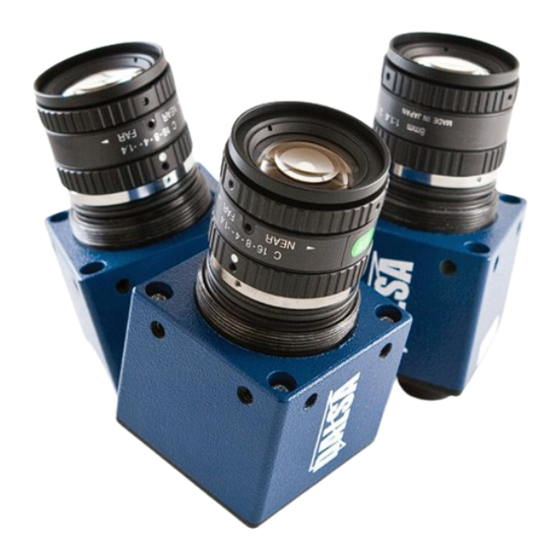
- Page 1 BOA Pro Smart Vision System Installation Manual Version 02 teledynedalsa.com/ipd...
- Page 2 All copyrights in this manual, and the hardware and software described in it, are the exclusive property of Teledyne DALSA, Inc. and its licensors. Claim of copyright does not imply waiver of Teledyne DALSA, Inc. or its licensors other rights in the work. See the following Notice of Proprietary Rights.
- Page 3 Certifications Declaration of Conformity Manufacturer Teledyne DALSA Corporation 605 McMurray Road Waterloo N2V 2E9 Ontario, Canada We declare that this product has been tested to comply with the EC Directive for a class A digital device in accordance with EN55022/CISPR22...
-
Page 4: Handling Precautions
Warranty Teledyne DALSA warrants the BOA Vision System against defects in materials and workmanship for a period of twenty four (24) months from the date of delivery. Teledyne DALSA and its representatives expressly disclaim any and all other warranties. Your sole remedy shall be repair or replacement of the BOA Vision System product and associated optional components, provided that the defective product is returned within the warranty period. -
Page 5: Table Of Contents
Table Of Contents ……………………....... Overview Introduction ……………………....... Product Support ……………………....... Components ……………………....... Connections Installation ……………………....... Cable Pinouts ……………………....... Cable Configurations ……………………....... Panel Link Module ……………………....... Ethernet Only Setup ……………………....... Ethernet and I/O Setup ……………………....... Getting Started Software ……………………....... Change the Address Using the iDiscover Utility ……………………....... -
Page 6: Introduction
BOA vision system is the hardware platform. Sherlock Embedded is the powerful and flexible professional machine vision software. Together they are the BOA Pro. BOA Pro is a fully integrated vision system in a compact “smart” camera format that has been specifically designed for industrial use. Packaged complete with application software embedded, BOA Pro provides power and flexibility for automated inspection for the factory floor. -
Page 7: Components
BOA Pro Vision System Components BOA Pro vision systems are shipped with the components listed below. Take a few moments to verify that everything has arrived in good condition. If your product has been visibly damaged during shipment or is missing parts, please contact your Teledyne DALSA representative immediately. -
Page 8: Installation
Installation Connecting the BOA Vision System This section details how to connect the BOA vision system with its associated components and factory environment. Camera Connectors and Indicators Designator Definitions 10/100 BaseT Ethernet connection. Provides the primary interface for configuring the camera, developing the application and monitoring results. -
Page 9: Cable Pinouts
Cable Pinouts The BOA vision system is compatible with M12 factory cordsets as show below: LAN Connector Pinout and Cordset Name RJ45 Pin PWR * GND * TXD- RXD+ TXD+ RXD- A-CAB-BVS-E8S-X I/O-PWR Connector Pinout and Cordset Name Color TRIG White Brown Green... -
Page 10: Cable Configurations
Cable Configurations The BOA vision system offers flexible cabling options to suit a number of application configurations: For single cable applications, the Ethernet cable can be used to supply power (referred to as “Passive Power over Ethernet”) and communications between the camera and the control environment. -
Page 11: Ethernet Only Setup
Ethernet Only Setup with Lamp Connect the M12-8 male end of the Ethernet cordset (A-BVS-E8S-X) to the M12-8 female connector labeled “LAN” on the camera. Connect the RJ45 end of the Ethernet cordset to the RJ45 connector labeled “CAM LAN” on the Panel Link breakout module (A-BVS-PL-100) Connect the RJ45 labeled “LAN”... -
Page 12: Ethernet And I/O Setup
Ethernet and I/O Setup with Lamp Connect the M12-8 male end of the Ethernet cordset (A-BVS-E8S-X) to the M12-8 female connector labeled “LAN” on the camera. Connect the RJ45 end of the Ethernet cordset to the RJ45 connector labeled “CAM LAN” on the Panel Link breakout module (A-BVS-PL-100) Connect the RJ45 labeled “LAN”... -
Page 13: Getting Started
Ethernet connection using a PC with the Sherlock Embedded Client software application. • You do not need to install software on a PC to monitor the BOA Pro system. • You do need to install the Sherlock Embedded Client Software to program and configure the BOA Pro system. -
Page 14: Idiscover Utility
You can then modify the BOA IP address, and click “Apply”. You cannot use this GUI to connect to BOA Pro cameras running the Sherlock Embedded software. In most cases you will need administrator privileges on your PC to access BOA. It may be necessary to customize the security settings on your browser. -
Page 15: Change The Address Using
Usually you do not need to reboot a PC after changing the network addressing. If you incorrectly set, or forgot, the new address of your BOA Pro, you can run the “iDiscover” utility. This utility is installed automatically when you install the Sherlock Embedded Client software on a PC. -
Page 16: Web Browser
Monitored when running or inspecting. This interface is also used for upgrading the BOA Pro firmware. The web server is accessed from a host PC using a Web Browser. The following browsers have been tested: Microsoft Internet Explorer version 8, Mozilla Firefox 5.0.1, Google Chrome 13.0.782.220. -
Page 17: Firmware Upgrading
“update.pak” (obtain from your Teledyne DALSA representative) on the connected PC and click the upgrade button. After a firmware upgrade, it is recommended that the programming PC be upgraded to a version of the Client software that matches the new firmware version. -
Page 18: Sherlock Embedded Client
CD that ships with the camera and is very easy to install. 1. Insert the BOA Pro CD into your PC’s drive. The installation utility should start automatically. (On Windows 7 you will be asked if you wish to run the setup.exe utility or open windows explorer.) -
Page 19: Specifications
Specifications General Specifications This following table lists the specifications of the BOA vision system: Specification Definition Memory Storage 256 MB Storage; 256MB Program 1/3 inch CCD; 7.4 μm pixel size Image Sensor Resolution 640x480, 1024x768, 1280x1024 Type Monochrome Progressive Scan Exposure 22 us to 1000 ms (range depends on the camera resolution) Acquisition... -
Page 20: Input Specifications
Input Specifications The BOA vision system provides two dedicated opto-isolated, polarity independent inputs. One of the inputs provides the acquisition Trigger function, while the other is general purpose. Specification Definition Voltage 12-30 V 0-3 V (12 V nominal threshold) Current 7.5 mA typ (24 V applied) Protection Resistance... -
Page 21: Output Specifications
Output Specifications The BOA vision system provides two dedicated opto-isolated, solid state relay outputs and a separate dedicated light strobe (pin 2 of lamp connector). Specification Definition Voltage (Vin) Load 24V maximum Current GPO[0:1] 100mA max (drives to OCMN when active) STRB 100mA max (drives to Vin when active) NOTE: Strobe timing is configured in the “Cam0”... -
Page 22: Output Control
Output Control with Sherlock Embedded The Sherlock Embedded application provides programmable options for controlling the outputs on BOA. The timing and polarity of the outputs is controlled in Digital IO Instructions. Each individual output can be controlled by an instruction in the Program Window (as detailed in the Sherlock Embedded Tutorial). -
Page 23: Panel Link Specifications
Panel Link Specifications The PL-100 module offers additional isolation for the BOA camera and simplifies wiring at the control panel. The module also provides power over Ethernet for single cable applications. I/O connections to the BOA camera should be wired to the TOP connectors on the PL- 100 (J2 and J3) directly. -
Page 24: Panel Link Wiring
Panel Link Wiring Illustration Note: BOA side is a 1:1 connection using A-BVS-IO8 ICMN PL Ethernet ports not shown ICMN ERTH To BOA OUT0 OCMN OUT1 OUT1 OCMN PL-100 OUT0 IN0- TRG- TRG+ TRG- IN0+ IN0- To Control Panel OU0+ OU0- OU1+ OU1-... -
Page 25: Serial Port Connection
Serial Port Connection The RS-232 serial port is accessible through the Lamp connector. By default, the serial port settings are set as follows: Port definition Setting Baud Rate 115200 Data Bits Parity None Stop Bits Flow Control None These port settings can be changed through the GUI by configuring the “Serial Port Properties”... -
Page 26: Boa Mechanicals
BOA Mechanical Dimensions Front View Back View Note: All dimensions in mm Side View Bottom View Version 02 teledynedalsa.com/ipd... -
Page 27: Pl-100 Mechanicals
A-BVS-PL-100 Mechanical Dimensions Top View Note: All dimensions in mm Side View Version 01 teledynedalsa.com/ipd...
Need help?
Do you have a question about the BOA Pro and is the answer not in the manual?
Questions and answers