Table of Contents
Advertisement
Advertisement
Table of Contents

Related Manuals for Nikon Eclipse LV100POL


Summary of Contents for Nikon Eclipse LV100POL
- Page 1 M357 E 05.9.NF.1 Polarizing Microscope ECLIPSE LV100POL Instructions...
-
Page 3: Warning And Caution Symbols
LV100POL. To ensure correct usage, please read this manual carefully before operating the product. • It is prohibited to reproduce or transmit this manual in part or whole without Nikon’s expressed permission. • The contents of this manual are subject to change without notice. -
Page 4: Warning
12V 50W SHORTLIFE halogen lamp (model name: OSRAM HLX 64610, OSRAM HLX 64611, or PHILIPS 7027). If you wish to buy these lamps, please contact your nearest Nikon representative. Note that if a lamp not specified is used for this product, the product is not approved as a UL... - Page 5 WARNING 7. Heat from the light source The lamp and the lamp house become extremely hot. To avoid burns, do not touch the lamp house while the lamp is lit or for thirty minutes after it is turned off. Furthermore, to avoid the risk of fire, do not place fabric, paper, or highly flammable volatile materials (such as gasoline, petroleum benzine, paint thinner, or alcohol) near the lamp house while the lamp is lit or for about thirty minutes after it is turned off.
-
Page 6: Caution
If water enters a component, immediately suspend use of this product, disconnect the power cord from the outlet, and contact your nearest Nikon representative. 3. Weak electromagnetic waves The product emits weak electromagnetic waves. There is a possibility that some precision electronic devices are affected by the electromagnetic waves. - Page 7 CAUTION 7. Cautions on lamp replacement • To prevent burn injuries, wait at least 30 minutes after the lamp is turned off to give it sufficient time to cool when replacing lamps. • To prevent electrical shock and damage to the microscope, always turn off the power switch (flip it to the “...
-
Page 8: Table Of Contents
CONTENTS WARNING and CAUTION Symbols ..............1 Meaning of the symbol used on the product ........... 1 WARNING ......................2 CAUTION ......................4 Part Names ....................8 1 Components and Controls ....................8 2 LV100POL with Epi Illuminator ..................10 3 Rear View ........................ - Page 9 Assembly ....................46 1 Attaching the Circular Graduated Stage ................48 2 Attaching the Condenser ....................48 3 Attaching the Nosepiece ....................49 4 Attaching Objectives ....................... 49 5 Attaching the Epi Illuminator (for the Episcopic Microscopy) ........50 6 Attaching the Lamp House and Replacing Lamps ............51 7 Attaching the Polarizing Intermediate Tube ..............
-
Page 10: Part Names
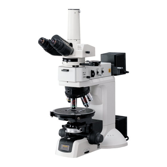
Part Names Components and Controls The figures in this section show the ECLIPSE LV100POL microscope with the diascopic illumination lamp house, the trinocular eyepiece tube, the vertical tube adapter, and the P swing-out condenser. Vertical tube adapter Binocular section Trinocular eyepiece tube Polarizing intermediate tube P-CL 1/4 λ... - Page 11 I. Part Names Photomicrographic equipment clamp screw Eyepiece Diopter adjustment ring Optical path selector lever Bertrand lens centering screws (both sides) Analyzer slider Bertrand lens turret Bertrand lens focus ring Slot (20 x 6 mm) Used for parts available on the market such as a compensator or so on.
-
Page 12: Lv100Pol With Epi Illuminator
LV100POL with Epi Illuminator The figure in this section shows the ECLIPSE LV100POL microscope with the epi illuminator, the episcopic illumination lamp house, the diascopic illumination lamp house, the trinocular eyepiece tube, the vertical tube adapter, and the P swing-out condenser. -
Page 13: Rear View
I. Part Names Rear View The figure below shows the ECLIPSE LV100POL microscope with the diascopic illumination lamp house, the trinocular eyepiece tube, and the vertical tube adapter. Connector for the episcopic illumination lamp house LAMP DC12V 50W Input voltage indication ECLIPSE LV100POL 100–240V~... -
Page 14: Microscopy
Microscopy This chapter explains microscopy procedures with the LV100POL microscope. • For detailed information about operations of parts of the microscope, refer to Page 22, “III. Operation of Each Part.” • If the microscope is not assembled yet, refer to Page 46, “IV. Assembly” and assemble the microscope before hand. - Page 15 II. Microscopy When necessary, push the filter selection switches on the base of the microscope. The NCB11 filter and ND8 filter can be Ach r 0. 8 0.90 JAPAN placed into the optical path. See Page 24. Filter type Intended use F.S.
- Page 16 When using the trinocular eyepiece tube, Set to the BINO position. set the optical path selector lever to the position where 100% light goes through the binocular eyepiece. See Page 27. Adjust the diopters and the interpupillary Adjust the diopters. distance.
- Page 17 II. Microscopy Rotate the nosepiece to locate the desired Switch to any desired objective. magnification objective into the optical path. Then, perform the microscopy. • Each time you change objectives, the field diaphragm and the condenser aperture diaphragm must be adjusted. - The field aperture should be adjusted so that its image circumscribes the view field.
-
Page 18: Orthoscopic Observation
Orthoscopic Observation This section describes the orthoscopic observation procedure. This observation method is the characteristic method for polarizing microscopes. In this method, the specimen is observed with the polarizer and the analyzer placed in the optical path. The shape of the specimen in the direction of the optical axis and its optical properties in the direction of the thickness can be observed. -
Page 19: Conoscopic Observation
II. Microscopy Conoscopic Observation This section describes the conoscopic observation procedure. This is the characteristic observation method of polarizing microscopes. In this method, the specimen is observed with the polarizer, the analyzer, and the Bertrand lens placed in the optical path. The specimen can be observed from various angles with diascopic light in the form of a single image. -
Page 20: Episcopic Microscopy (With The Epi Illuminator Option)
Episcopic Microscopy (with the Epi Illuminator Option) When the epi illuminator is attached, you can perform the episcopic microscopy with the episcopic illumination lamp house. Check the cumulative lit-on time of the lamp before the microscopy. If the cumulative lit-on time has exceeded the average operation life, replace the lamp with new one. - Page 21 II. Microscopy Pull out the polarizer slider on the epi Remove the analyzer from the optical path. illuminator to remove the polarizer from the optical path. See Page 36. A. ST O F. ST O Push in the analyzer slider on the polarizing intermediate tube to remove the Move the analyzer from the optical path.
- Page 22 Rotate the nosepiece to locate the desired Adjust the field diaphragm and the magnification objective into the optical aperture diaphragm. path. Then, perform the microscopy. • Each time you change objectives, the field diaphragm and the condenser aperture diaphragm on the epi illuminator must be A.
-
Page 23: Photomicroscopy
II. Microscopy Photomicroscopy For detailed information for the camera, photomicroscopic software, and PC, refer to the operating manuals provided with the respective products. The following instructions assume that the digital camera DS-5M and the camera control unit DS-L1 are used. Adjust the microscope for proper image observation. -
Page 24: Operation Of Each Part
Operation of Each Part Power ON / OFF The power switch for the microscope is located beside the AC inlet on the rear side. To turn on the microscope, push the power switch to CAUTION ! - High Temperature - Do not touch the lamphouse while the lamp is lit. -
Page 25: Operation For The Illumination
III. Operation of Each Part Operation for the Illumination To select the episcopic illumination or the diascopic illumination When the epi illuminator and the episcopic illumination Epi/dia selector switch lamp house are attached, the epi/dia selector switch on the left side of the microscope can be used to select either the episcopic illumination or the diascopic illumination. -
Page 26: Filter Operation
Filter Operation For the diascopic illumination Two filters are installed in the base of the microscope. And filter selector switches for the filters are located at the right side of the microscope. To locate the filter into the optical path, push the lower side of the switch. To remove the filter from the optical path, push the upper side of the switch. -
Page 27: Coarse Focus Knob / Fine Focus Knob Operation
III. Operation of Each Part Coarse Focus Knob / Fine Focus Knob Operation Knob rotation and stage vertical movement The right figure relates the rotation direction of the coarse focus knob/fine focus knob to the vertical movement of the stage. •... -
Page 28: Stage Rotation
Stage Rotation Caution Do not try to put a large specimen on the stage if the specimen is larger than the stage. Stage rotation To rotate the circular graduated stage, loosen the stage rotation clamp screw and turn the Verniers whole stage carefully by hand. -
Page 29: Trinocular Eyepiece Tube Operation
III. Operation of Each Part Trinocular Eyepiece Tube Operation Optical path selection BINO The optical path selector lever can be used to BINO & PHOTO select the way to distribute light to the PHOTO binocular part and the vertical tube. When the lever is pushed in as far as it goes, the distribution of light for the binocular part is 100%. -
Page 30: Diopter Adjustment
Diopter Adjustment Diopter adjustment compensates for differences in visual acuity between the right and left eyes. This adjustment improves binocular observation and minimizes focal deviation when switching objectives. Focus on the crosshair with the right eye. In the case of a polarization microscope, since an eyepiece containing crosshairs is used for the right eye, the procedure for adjusting the diopter differs from that of an ordinary... -
Page 31: Condenser Operation
III. Operation of Each Part Condenser Operation The P swing-out condenser must be attached to perform the polarization microscopy. How to use the P swing-out condenser The top lens of the P swing-out condenser can be moved outside the optical path with the Top lens swing-out lever. -
Page 32: Focusing And Centering The Condenser
Focusing and Centering the Condenser At the first time usage of the microscope or after attaching the condenser, focus and center the condenser so that the light through the condenser is focused on the correct position of the specimen surface (at the center of the optical path). 1 Perform steps in Page 12, “1 Diascopic Bright- Field Microscopy,”... - Page 33 III. Operation of Each Part For the Bright-field Microscopy and the Orthoscopic Microscopy The aperture diaphragm is important because it is related to the resolution, contrast, depth of focus, and brightness of the optical image. Turning the condenser aperture diaphragm ring changes the size of the aperture diaphragm.
-
Page 34: Adjusting The Field Diaphragm
Adjusting the Field Diaphragm The field diaphragm restricts illumination to the area of the specimen that is being viewed. Operating the field diaphragm control changes the Ach r 0. 8 0.90 JAPAN size of the field diaphragm. For normal observation, the size of the diaphragm should be such that it is just outside the edge of the viewfield. -
Page 35: Centering The Objective
III. Operation of Each Part Centering the Objective To perform the polarization microscopy, the center of the objective optical path must be aligned to the rotation center of the circular graduated stage. This product comes with the centering nosepiece. You can perform the centering adjustment for each objective. Required tools two centering tools (provided with the nosepiece) 1 Before centering the objectives, focus on a specimen using the 10x objective. -
Page 36: Oil Immersion Operation
Oil Immersion Operation Objectives marked “oil” are oil-immersion type objectives. These objectives are used with immersion oil (option) between the specimen and the tip of the objective. Bubbles in the oil will adversely affect the viewing of the image. Be careful to prevent bubbles from forming. To check for air bubbles, fully open the field diaphragm and aperture diaphragm, remove the eyepiece, and examine the pupil (bright round section) of the objective inside the... -
Page 37: Water Immersion Operation
III. Operation of Each Part Water Immersion Operation Objectives marked “WI” or “W” are water-immersion type objectives. These objectives are used with immersion water (distilled water or physiological saline) applied between the specimen and the tip of the objective. Microscopy procedures are the same as for oil-immersion type objectives. Since water evaporates readily, monitor the immersion water during observation. -
Page 38: Operation Of The Polarizers
Operation of the Polarizers Polarizer for the diascopic microscopy To perform the diascopic polarization microscopy, attach the polarizer for the diascopic microscopy into the polarizer rotation ring. Rotate the ring Ach r 0. 8 0.90 JAPAN On the polarizer, there is a protrusion to identify to the “0”... -
Page 39: Operation Of The Analyzer
III. Operation of Each Part Operation of the Analyzer Attach/detach the analyzer The polarizing intermediate tube has the analyzer slider. The analyzer can be placed into the optical Analyzer path with the operation of the slider. slider To place the analyzer into the optical path, pull out the slider. -
Page 40: Azimuth Adjustment Of The Polarizer And Analyzer
Azimuth Adjustment of the Polarizer and Analyzer For the diascopic observation 1 Remove the polarizer and analyzer from the optical path. 2 Focus on the specimen. 3 Pull out the analyzer slider and move the analyzer Analyzer into the optical path. scale: 0 4 Turn the analyzer rotation dial and align at the “0”... -
Page 41: Bertrand Lens Operation
III. Operation of Each Part Bertrand Lens Operation The polarizing intermediate tube has the Bertrand lens. The Bertrand lens can be placed into the optical path to perform the conoscope observation. Setting the Bertrand lens Put the Bertrand lens turret in the “B” position to move the Bertrand lens into the optical path. -
Page 42: Operation Of Examination Plates
How to Use Examination Plates The polarizing intermediate tube has a slot for examination plates. It is used not only for the standard P-CL 1/4 λ & tint plate but also for the optional P-CS Senarmont compensator, the PCW quartz wedge, or so on to perform the retardation measurement. To use an objective of 10x or higher magnification in standard observation, place the top lens of the P swing-out condenser into the optical path. - Page 43 III. Operation of Each Part P-CQ quartz wedge The P-CQ quartz wedge is used by inserting it into the slot of the intermediate tube in place of the P-CL 1/4 λ & tint plate. The quartz wedge is engraved with a scale and can be used for rough measurement of retardation in the range of 1 λ...
-
Page 44: Episcopic Microscopy
Episcopic Microscopy To perform episcopic microscopy, attach the LV-UEPI universal epi illuminator and a lamp for the epi illumination to the microscope. 1. Switching the Episcopic Illumination You can switch the illumination between the bright- field and the dark-field to be used for the episcopic microscopy by operating the illumination selector lever on the right side of the epi illuminator. - Page 45 III. Operation of Each Part 2. Field Diaphragm in the Epi Illuminator The field diaphragm restricts illumination to the area Field diaphragm of the specimen that is being viewed. Operating the open/close lever field diaphragm open/close lever changes the size of the field diaphragm.
- Page 46 3. Aperture Diaphragm in the Epi Illuminator Since the aperture diaphragm is used for adjusting the Aperture diaphragm open/close lever numerical aperture of the illumination system, this diaphragm is related to the resolution, contrast, and depth of focus of the optical image. Generally, the aperture diaphragm should be adjusted to about 70 to 80% of the numerical aperture of the objective.
-
Page 47: Image Capturing
III. Operation of Each Part Image Capturing Images under the microscope observation can be captured by attaching a camera head to the trinocular eyepiece tube. For detailed information, refer to the operating manual provided with the camera head or camera control software. -
Page 48: Assembly
Assembly Assemble each part of the microscope by referring to the diagram on the next page. WARNING • Before assembling the microscope, be sure to read the WARNING and CAUTION at the beginning of this instruction manual and follow the instructions written therein. •... - Page 49 IV. Assembly Assembling the ECLIPSE LV100POL TV vertical TV vertical adapter adapter 0.55x Eyepiece Eyepiece Binocular Trinocular eyepiece tube eyepiece tube P-CL 1/4 λ & tint plate P-CS Senarmont compensator Polarizing intermediate tube P-CQ quartz wedge (with analyzer slider) Polarizer...
-
Page 50: Attaching The Circular Graduated Stage
Attaching the Circular Graduated Stage 1 Remove the cushioning material from the Circular graduated substage section and turn the coarse focus stage handle until the elevating section is brought to the uppermost position. 2 Place the circular graduated stage on the substage. -
Page 51: Attaching The Nosepiece
IV. Assembly Attaching the Nosepiece Attach the P-N quintuple centering nosepiece on this Nosepiece clamp screw microscope. 1 Fully loosen the nosepiece clamp screw located on the right side of the microscope arm using the hexagonal screwdriver. 2 Insert the nosepiece along the guide groove located on the lower side of the microscope arm. -
Page 52: Attaching The Epi Illuminator (For The Episcopic Microscopy)
Attaching the Epi Illuminator (for the Episcopic Microscopy) 1 Loosen sufficiently the illuminator clamp Hexagonal socket screw on the front of the microscope arm head bolts (x4) using the hexagonal screwdriver. 2 Mount the epi illuminator onto the microscope arm and tighten the illuminator clamp screw. -
Page 53: Attaching The Lamp House And Replacing Lamps
(for at least 30 minutes after the lamp is turned off), before replacing lamps. • Use the Nikon LV-LH50PC Halogen Lamphouse for the lamp house. • Use the Nikon LV-HL50W 12V 50W LONGLIFE Halogen Lamp or non-Nikon 12V 50W SHORTLIFE halogen lamp (model OSRAM HLX 64610, OSRAM HLX 64611, or PHILIPS 7027) for the lamp. - Page 54 2. Replacing lamps Lamps can be replaced without having to detach the lamp house from the microscope. Before performing the following procedures, turn off the power supply for the microscope (press the “ ” side) and unplug the power cord from the wall outlet. And check that the lamp and the lamp house are sufficiently cooled down.
-
Page 55: Attaching The Polarizing Intermediate Tube
IV. Assembly Attaching the Polarizing Intermediate Tube 1 Loosen sufficiently the clamp screw for the Polarizing intermediate tube on the microscope arm (or on intermediate the illuminator). tube Use the tool provided with the microscope to loosen the clamp screw for the epi illuminator. 2 Fit the circular dovetail of the polarizing intermediate tube into the circular dovetail Clamp screw... -
Page 56: Attaching A Camera (For The Trinocular Eyepiece Tube)
Attaching a Camera (for the Trinocular Eyepiece Tube) To attach a photomicrography device such as a camera onto the vertical tube of the trinocular eyepiece tube, you must use two adapters: First, attach the TV vertical tube adapter onto the trinocular eyepiece tube. -
Page 57: Connecting The Power Cord
IV. Assembly Connecting the Power Cord WARNING Be sure to use the specified power cord. Using a wrong power cord may result in malfunctions or fire. Also, the product is classified as subject to Class I protection against electrical shock. Make sure it is connected to an appropriate ground terminal (protective earth terminal). -
Page 58: Troubleshooting
Troubleshooting Improper use of the microscope may adversely affect performance, even if the microscope is not damaged. If any of the problems listed in the table below arise, take the countermeasures indicated. Viewing Problems and Control Problems Problem Cause Countermeasure The lamp is not attached correctly. - Page 59 V. Troubleshooting Problem Cause Countermeasure The aperture diaphragm is stopped Open the diaphragm to a suitable size. Dirt or dust is seen in down too far. (p. 31 and 44) the viewfield. Dirt or dust exists on the lens, eyepiece, Clean the components.
- Page 60 Problem Cause Countermeasure The brightness is The lamp voltage is too low. Adjust the brightness with the insufficient. brightness control knob. (P.23) (Refer to the A ND filter is placed in the optical path. Remove the ND filter from the optical troubleshooting for the path.
-
Page 61: Electrical System Problems
V. Troubleshooting Problem Cause Countermeasure The coarse torque adjustment ring is Loosen the torque adjustment ring The coarse focus knob tightened too much. adequately. (P.25) is heavy in rotation. The coarse focus stopper ring is locked Turn the coarse focus stopper ring to to restrict the upper limit. -
Page 62: Care And Maintenance
Care and Maintenance Nikon recommends daily care and maintenance for maintaining the performance as long as possible. Do not let dust, fingerprint, etc. get on the lenses. Dirt on the lenses, filters, and the like will adversely affect the optical performance of the microscope. -
Page 63: Cleaning Lenses And Filters
• Before putting on the dust-proof cover, turn off the power switch of the microscope (flip it to the “ ” position) and wait until the lamp house gets cool sufficiently Regular Inspection Periodical inspections of this product are recommended in order to maintain peak performance. Contact your nearest Nikon representative for details. -
Page 64: Specifications
Specifications ECLIPSE LV100POL Model Optical system CFI60 system (chromatic aberration free infinity system) Illumination system Epi/dia selector type Episcopic illumination: Built-in type lamp power supply Specified illuminator: LV-UEPI Universal Epi Illuminator (NCB11, ND4, and ND16 are installed and can be replaced by users) - Page 65 VII. Specifications Safety standards • This is UL-listed product. (UL61010-1) compliance • This equipment has been tested and found to comply with the limits for a Class A digital device, pursuant to Part 15B of the FCC Rules. These limits are designed to provide reasonable protection against harmful interference when the equipment is operated in a commercial environment.
Need help?
Do you have a question about the Eclipse LV100POL and is the answer not in the manual?
Questions and answers