Rigol M300 Series User Manual
Data acquisition/switch system
Hide thumbs
Also See for M300 Series:
- Quick manual (43 pages) ,
- Selection manual (42 pages) ,
- Manual (7 pages)

Related Manuals for Rigol M300 Series


Summary of Contents for Rigol M300 Series
- Page 1 RIGOL User’s Guide M300 Series Data Acquisition/Switch System Dec. 2014 RIGOL Technologies, Inc.
-
Page 3: Trademark Information
Software Version 00.02.00.04.19 Software upgrade might change or add product features. Please acquire the latest version of the manual from RIGOL website or contact RIGOL to upgrade the software. Notices RIGOL products are covered by P.R.C. and foreign patents, issued and ... -
Page 4: Safety Requirement
RIGOL Safety Requirement General Safety Summary Please review the following safety precautions carefully before putting the instrument into operation so as to avoid any personal injury or damage to the instrument and any product connected to it. To prevent potential hazards, please use the instrument only specified by this manual. - Page 5 Do not touch exposed junctions and components when the unit is powered. Do Not Operate With Suspected Failures. If you suspect damage occurs to the instrument, have it inspected by RIGOL authorized personnel before further operations. Any maintenance, adjustment or replacement especially to circuits or accessories must be performed by RIGOL authorized personnel.
-
Page 6: Handling Safety
If a battery is supplied, it must not be exposed to high temperature or in contact with fire. Keep it out of the reach of children. Improper change of battery (note: lithium battery) may cause explosion. Use RIGOL specified battery only. Handling Safety. -
Page 7: Safety Terms And Symbols
RIGOL Safety Terms and Symbols Terms Used in this Manual. These terms may appear in this manual: WARNING Warning statements indicate conditions or practices that could result in injury or loss of life. CAUTION Caution statements indicate conditions or practices that could result in damage to this product or other property. -
Page 8: Allgemeine Sicherheits Informationen
RIGOL Allgemeine Sicherheits Informationen Überprüfen Sie diefolgenden Sicherheitshinweise sorgfältigumPersonenschädenoderSchäden am Gerätundan damit verbundenen weiteren Gerätenzu vermeiden. Zur Vermeidung vonGefahren, nutzen Sie bitte das Gerät nur so, wiein diesem Handbuchangegeben. Um Feuer oder Verletzungen zu vermeiden, verwenden Sie ein ordnungsgemäßes Netzkabel. - Page 9 Wenn Sie am Gerät einen Defekt vermuten, sorgen Sie dafür, bevor Sie das Gerät wieder betreiben, dass eine Untersuchung durch RIGOL autorisiertem Personal durchgeführt wird. Jedwede Wartung, Einstellarbeiten oder Austausch von Teilen am Gerät, sowie am Zubehör dürfen nur von RIGOL autorisiertem Personal durchgeführt werden. Belüftung sicherstellen.
-
Page 10: Sicherheits Begriffe Und Symbole
RIGOL Sicherheits Begriffe und Symbole Begriffe in diesem Guide. Diese Begriffe können in diesem Handbuch auftauchen: WARNING Die Kennzeichnung WARNING beschreibt Gefahrenquellen die leibliche Schäden oder den Tod von Personen zur Folge haben können. CAUTION Die Kennzeichnung Caution (Vorsicht) beschreibt Gefahrenquellen die Schäden am Gerät hervorrufen können. -
Page 11: General Care And Cleaning
RIGOL General Care and Cleaning General Care Do not store or leave the instrument where it may be exposed to direct sunlight for long periods of time. Cleaning Clean the instrument regularly according to its operating conditions. To clean the exterior surface, perform the following steps: Disconnect the instrument from all power sources. -
Page 12: M300 Overview
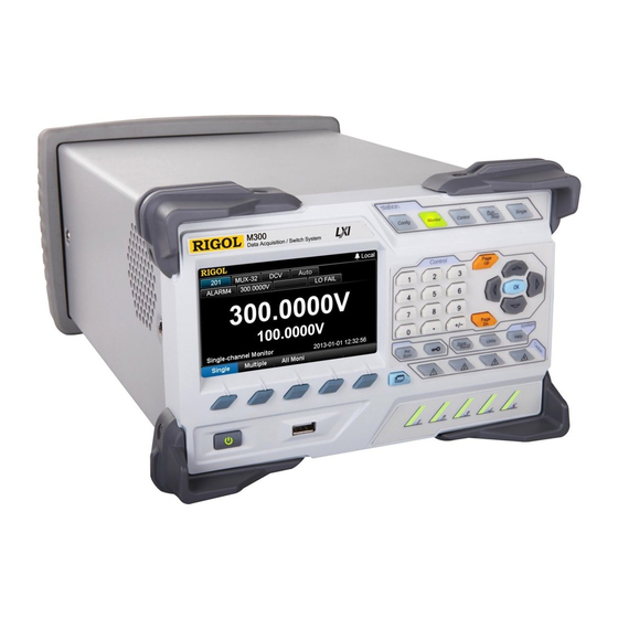
RIGOL M300 Overview The M300 series data acquisition/switch system provides 5 slots to accept any combination of 8 kinds of plug-in modules, including a DMM module, multiple multiplexers, an actuator, a matrix switch module and a multifunction module. With its modular structure, it combines precision measurement capability with flexible signal connections and can provide versatile solutions for the applications that require multiple points or signals to be tested. -
Page 13: Document Overview
RIGOL Document Overview Main topics in this manual: Chapter 1 Quick Guide This chapter introduces the front panel, rear panel, user interface and plug-in modules of the M300 as well as the precautions when using it for the first time. - Page 14 RIGOL Format Conventions in this Manual: 1. Key: The front panel key is denoted by the format of “Text Box + Button Name (Bold)”. For example, Utility denotes the Utility key. 2. Menu: The menu is denoted by the format of “Character Shading + Menu Word (Bold)”.
-
Page 15: Table Of Contents
Contents RIGOL Contents Guaranty and Declaration ................. I Safety Requirement ................II General Safety Summary ................II Safety Terms and Symbols ................ V Allgemeine Sicherheits Informationen ............VI Sicherheits Begriffe und Symbole ............VIII General Care and Cleaning ............... IX Environmental Considerations .............. - Page 16 RIGOL Contents Configuration Copy ................ 2-39 Channel Monitor ................... 2-44 Single-channel Monitor ..............2-44 Multi-channel Monitor ..............2-46 All Channel Monitor ................ 2-46 Module Control ..................2-47 To Control MC3120 ................ 2-48 To Control MC3132 ................ 2-51 To Control MC3164 ................ 2-54 To Control MC3324 ................
- Page 17 Contents RIGOL AC Characteristics .................. 6-3 Frequency and Period Characteristics ............6-6 Temperature Characteristics ..............6-8 Module Specifications ................6-10 MC3120/MC3132/MC3164/MC3324/MC3416/MC3648 ......6-10 MC3534 ..................6-12 General Specifications ................6-13 Chapter 7 Appendix ................7-1 Appendix A: Accessories and Options List ..........7-1 Appendix B: Definitions of the Pins of the 78-pin Interface of the Plug-in Modules ....................
-
Page 19: Chapter 1 Quick Guide
Chapter 1 Quick Guide RIGOL Chapter 1 Quick Guide This chapter guides users to quickly get familiar with the front/rear panels, user interface as well as the measurement connections of the M300. Topics in this chapter: General Inspection Appearance and Dimensions ... -
Page 20: General Inspection
RIGOL would not be responsible for free maintenance/rework or replacement of the unit. 2. Inspect the instrument. In case of any damage, or defect, or failure, notify your RIGOL sales representative. 3. Check the Accessories Please check the accessories according to the packing lists. If the accessories are incomplete or damaged, please contact your RIGOL sales representative. -
Page 21: Appearance And Dimensions
Chapter 1 Quick Guide RIGOL Appearance and Dimensions Figure 1-1 Front View (Unit: mm) Figure 1-2 Side View (Unit: mm) M300 User’s Guide... -
Page 22: Front Panel
RIGOL Chapter 1 Quick Guide Front Panel Figure 1-3 Front Panel of M300 4.3 inches high-resolution color LCD displaying the menu, configuration guide, measurement parameters, system status and prompt messages. Function Keys Configure the scan list and the measurement parameters of each channel. - Page 23 Chapter 1 Quick Guide RIGOL In all-channel monitor function, you can monitor all the channels in the scan list. Control the modules currently inserted. Control the status of each channel of the modules. Reset the modules. Configure the DIO and TOT channels of multifunction ...
- Page 24 RIGOL Chapter 1 Quick Guide When the instrument is in local mode, pressing this key can lock the front panel. At this point, all the keys at the front panel except this key become invalid. Press and hold this key to unlock the front panel.
-
Page 25: Module Indicators
Chapter 1 Quick Guide RIGOL Menu Softkeys Correspond to the menus on the screen. Pressing any softkey can enable the corresponding menu. View Switch View the scan history information, channel status table, measurement curve and channel information. Scan history information: view the start time, scan sweep, count, ... -
Page 26: Rear Panel
RIGOL Chapter 1 Quick Guide Rear Panel 2 3 4 Figure 1-4 Rear Panel of M300 Slots The M300 provides 5 slots for 5 modules. The 5 slots from left to right in the figure above correspond to the 5 module indicators at the front panel respectively. - Page 27 Chapter 1 Quick Guide RIGOL external interface (namely Analog Bus Interface). The analog bus interface is a 9-pin female interface. Definition Current Input LoSense HiSense Float GND Analog Bus Interface DMM Module Power Fuse The AC power supply from the power socket is divided into two paths with one for the DMM module and the other for other circuits except the DMM module.
- Page 28 RIGOL Chapter 1 Quick Guide [RS-232/Alarms/Ext Trig] Mixed Interface (Male) This interface is 25-pin male interface. You can convert this interface into two 9-pin interfaces using the Mixed Interface Convert Cable (accessory). This breakout cable consists of a 9-pin male interface used as a standard RS232 interface and another a 9-pin female interface used for alarm output, external trigger signal input, etc.
-
Page 29: Power Socket
Chapter 1 Quick Guide RIGOL “Falling” in Edge item. If the external trigger signal is continuous pulse, please make sure the pulse period is larger than 100μs. GPIB The M300 conforms to the IEEE-488.2 standard. Via this interface, the M300 can be controlled remotely via a PC with a GPIB interface. -
Page 30: Power On Inspection
Check whether the correct power voltage is selected. Please select the proper power voltage according to the power supply voltage. Restart the instrument after finishing the above inspections. If it still does not work correctly, please contact RIGOL. 1-12 M300 User’s Guide... -
Page 31: User Interface
Chapter 1 Quick Guide RIGOL User Interface Status Content Area Menu Figure 1-5 User Interface 1. Status Bar Help Displayed when the built-in help is enabled. Error Displayed when an error occurs. Displayed when the keyboard is locked. Displayed when an alarm is generated. -
Page 32: To Input Filename
RIGOL Chapter 1 Quick Guide To Input Filename M300 supports filenames consisting of Chinese characters, English letters and numbers. The length of the filename can not exceed 12 bytes. The filename input interface is as shown in the figure below. - Page 33 Chapter 1 Quick Guide RIGOL Switch the Input Mode Press Ch/A/a to switch the input mode to Chinese, English uppercase or English lowercase. Chinese: can input Chinese characters and number (from 0 to 9) and is displayed in the “Input Mode Icon Area”.
-
Page 34: Plug-In Module Overview
RIGOL Chapter 1 Quick Guide Plug-in Module Overview The M300 provides 8 kinds of modules. These include a DMM module, 20-channel multiplexer, 32-channel multiplexer, 64-channel multiplexer, multi-function module, etc. This section introduces the functions and characteristics of each module. Outside View Drawing of the Module... -
Page 35: Insert The Module Into The Mainframe
Chapter 1 Quick Guide RIGOL Insert the Module into the Mainframe Please turn the mainframe off and insert the modules following the instructions below. As shown in Figure 1-7, there is a golden circuit board edge both on the top and bottom of the module. -
Page 36: Module Overview
RIGOL Chapter 1 Quick Guide Module Overview MC3065 (DMM Module): The DMM module is used to measure the signals under test and has 6½ digit reading resolution. The measurement functions include DCV, ACV, 2-wire resistance, 4-wire resistance, frequency, period, temperature and any sensor. - Page 37 Chapter 1 Quick Guide RIGOL 4 current channels are used in combination with the DMM module to measure DC current or AC current. All channels in the scan list are break-before-make. In any case, you cannot close multiple channels on this module.
-
Page 38: To Use The Built-In Help System
RIGOL Chapter 1 Quick Guide To Use the Built-in Help System The built-in help system of M300 provides the help information about any front panel key and menu. To acquire the help information of any front panel key or menu, press Help (the backlight goes on and “Help”... -
Page 39: Measurement Connections
Cut off all the power supplies before opening the terminal block or removing the terminal block from the module. Place the terminal block with the front (with the RIGOL caption) facing downward and pull the two latches in the arrow direction in the figure below and press them down. - Page 40 For the connection method of each module and the corresponding terminal block as well as the specification requirements of the connecting cable, please log in RIGOL official website (www.rigol.com) to get more related materials. When using the mutliplexer module for measurement, make sure that both ...
- Page 41 Chapter 1 Quick Guide RIGOL Table 1-2 Measurement Connections DCV/ACV/FREQ/PERIOD/Sensor DCI/ACI/ Sensor (DCI) (DCV, FREQ) Signal to be measured Signal to be measured CH21 Note: Only available for the channel 21 to channel 24 of MC3324. 2WR/RTD/Thermistor/ 4WR/RTD 4W/ Sensor (4WR)
- Page 42 RIGOL Chapter 1 Quick Guide Connect the terminal block to the module via interface 1 (the interface definition is in Figure 1-7) on the module and screw down the two screw rods onto the nuts on the module. Close the upper cover of the terminal block.
-
Page 43: To Replace The Fuse
Chapter 1 Quick Guide RIGOL To Replace the Fuse If a new fuse is required, please refer to the following steps. Turn off the instrument and remove the power cord. Insert the small straight screw driver into the slot at the power socket and pry out the fuse seat. -
Page 44: Menu Quick Navigation
RIGOL Chapter 1 Quick Guide Menu Quick Navigation This section provides the structures of the main menus for M300 to guide users to quickly get familiar with the operations. For more detailed information, please refer to “Front Panel Operations”. Config 1-26 M300 User’s Guide... -
Page 45: Monitor
Chapter 1 Quick Guide RIGOL Monitor View Switch Key 1-27 M300 User’s Guide... -
Page 46: Control
RIGOL Chapter 1 Quick Guide Control Alarm Channel Setting Keys 1-28 M300 User’s Guide... -
Page 47: Chapter 2 Front Panel Operations
Chapter 2 Front Panel Operations RIGOL Chapter 2 Front Panel Operations This chapter introduces in details the front panel operation methods and functions of M300. Topics in this chapter: Scan Configuration Channel Monitor Module Control Alarm Channel Setting ... -
Page 48: Scan Configuration
RIGOL Chapter 2 Front Panel Operations Scan Configuration Press Config at the front panel to configure M300 to create a scan (create and edit the scan list and configure the parameters of each channel). During the scan, each time the DMM module is connected to one channel in the scan list and executes a measurement according to the channel configuration. -
Page 49: Sweep Count
Chapter 2 Front Panel Operations RIGOL (each English letter or number occupies 1 byte and each Chinese character occupies 2 bytes). To modify the name of the scan list created, please select Scan List firstly and press OK to enter the filename input interface. -
Page 50: Absolute Time
RIGOL Chapter 2 Front Panel Operations Advanced Source (Available only when the DMM module is not installed or disabled) This setting is only available when an external digital multimeter is used. The advanced source provides the advanced channel signal. When receiving the advanced channel signal, the instrument disconnects the channel currently selected and closes the next channel in the scan list. -
Page 51: Alarm Channel
Chapter 2 Front Panel Operations RIGOL absolute time scan mode. When the trigger mode is “AbsTime”, select AbsTime using the up/down direction keys and set the desired time using the numeric keyboard. The time format is “Month-Date Hour:Minute:Second”. You need to set a valid time. -
Page 52: To Edit The List
RIGOL Chapter 2 Front Panel Operations To Edit the List Press ConfigEdit to enter the scan list editing interface. Figure 2-2 Scan List Editing Interface Create a new channel configuration. Press this softkey to enter the channel configuration guide. Finish all the configurations according to the introductions in “Channel Configuration”... -
Page 53: To Save The List
Chapter 2 Front Panel Operations RIGOL Search When a great number of channels are added into the scan list, you can press Page Dn Search, use the numeric keyboard to input the desired channel number and then press OK to quickly locate this channel. You can copy, modify or delete the channel configuration located. -
Page 54: Trigger Mode
RIGOL Chapter 2 Front Panel Operations Trigger Mode The M300 provides 5 trigger modes including auto trigger, manual trigger, external trigger, absolute time trigger and alarm trigger. Auto Trigger In auto trigger mode, the scan rate is determined by the specified interval. If the... -
Page 55: External Trigger
Chapter 2 Front Panel Operations RIGOL alarm data in the non-volatile memory automatically. You can press at the front panel to view the history measurement data (including the maximum, minimum, average and standard deviation). External Trigger To use the external trigger mode, first use the mixed-interface separator line (accessory) to convert the [RS-232/Alarms/Ext Trig] interface at the rear panel to two 9-pin interfaces. -
Page 56: Absolute Time Trigger
RIGOL Chapter 2 Front Panel Operations Absolute Time Trigger To use the absolute time trigger mode, set an accurate system time for the instrument by referring to “Date” and “Time”. Then select absolute time trigger mode and set a time. The instrument executes a scan when the system time reaches the specified time. -
Page 57: Alarm Trigger
Chapter 2 Front Panel Operations RIGOL Alarm Trigger To use the alarm trigger mode, configure the alarm by referring to “Alarm Configuration” and select alarm trigger mode, then select an alarm channel. The instrument executes a scan when an alarm is generated in the specified alarm channel. -
Page 58: Channel Configuration
RIGOL Chapter 2 Front Panel Operations Channel Configuration After creating a new scan list and configuring proper parameters (such as the scan sweep and trigger mode), you need to add channels into the scan list and configure the measurement, scaling, alarm and advanced parameters of the channels. The M300 provides special channel configuration guide for you to easily finish the channel configuration. - Page 59 Chapter 2 Front Panel Operations RIGOL Measurement Configuration The first step in the channel configuration guide: select the channel number, select the measurement function of the specified channel and configure the basic measurement parameters of the selected function. Figure 2-4 Measurement Configuration Channel Number Select the desired channel number.
- Page 60 RIGOL Chapter 2 Front Panel Operations Explanation: If you want to configure the channel of the multiplexer (MC3132 and MC3164), add it to the scan list and use it for measurement, you need to first insert and enable the DMM module (Utility DMM “ON”) or connect an external digital multimeter.
- Page 61 Chapter 2 Front Panel Operations RIGOL Scaling Configuration The second step of the channel configuration guide: configure the scaling parameters. Figure 2-5 Scaling Configuration Note: For multiplexer channels that are using the “SENSOR” function and the DIO and TOT channels of the multifunction module, the configuration guide does not contain scaling configuration.
- Page 62 RIGOL Chapter 2 Front Panel Operations If the channel using the scaling function is removed from the scan list, the scaling function of the channel will be disabled but the scaling coefficients will not be reset. When the channel is added into the scan list again (without changing the measurement function), the scaling function will be enabled and the scaling coefficients remain unchanged.
-
Page 63: Alarm Configuration
Chapter 2 Front Panel Operations RIGOL Alarm Configuration The third step of channel configuration guide: configure the alarm parameters. Figure 2-6 Alarm Configuration Note: For multiplexer channel, if the DMM module is not currently inserted or it is inserted but is not enabled, the configuration guide does not contain “Alarm Configuration”... - Page 64 RIGOL Chapter 2 Front Panel Operations Select the Alarm Mode Enter the alarm configuration interface, Mode is selected by default and you can use the left/right direction keys to select the desired mode. If the DIO channel is currently used, the options available are “OFF” and “ON”. If the TOT channel is currently used, the options available are only “NONE”...
- Page 65 Chapter 2 Front Panel Operations RIGOL outside the range but when you press OK, an error prompt message will be displayed. The instrument can also ignore some digits and alarm when the values of some digits are satisfied. Use “.” on the numeric keyboard to set the digits to be ignored and the corresponding position will display “x”.
-
Page 66: Advanced Configuration
RIGOL Chapter 2 Front Panel Operations Advanced Configuration The fourth step of the channel configuration guide: configure the advanced measurement parameters relating to the function selected. Figure 2-7 Advanced Configuration The advanced parameters to be configured differ when different function is selected in the “Measurement Configuration”... -
Page 67: Channel Configuration When Using External Dmm
Chapter 2 Front Panel Operations RIGOL Channel Configuration When Using External DMM For the multiplexer channels, if the DMM module is not inserted or enabled, you can connect an external DMM to realize scan and measurement function (for the connection method, please refer to ”To Connect Instruments”). -
Page 68: Measurement Parameter Configuration
RIGOL Chapter 2 Front Panel Operations Measurement Parameter Configuration This section introduces the measurement parameters (such as the range and integration time) that can be configured in the first and fourth steps of the configuration guide. The parameters available for configuration vary for each measurement function as shown in the table below. - Page 69 Chapter 2 Front Panel Operations RIGOL To Set the Range The setting modes of range include “Auto” and “Manual”. In auto range mode, the instrument selects the proper range for each measurement according to the input signal automatically. In the manual range mode, users can select a fixed range for each channel.
- Page 70 RIGOL Chapter 2 Front Panel Operations Integration Time The Integration time is the period of time that the instrument’s analog-to-digital (A/D) converter samples the input signal for a measurement. The longer the integration time is, the slower the measurement speed and the better the measurement resolution will be.
-
Page 71: Auto Zero
Chapter 2 Front Panel Operations RIGOL Auto Zero Auto Zero (AZ) is applicable to DCV, DCI, 2WR, 4WR, TEMP (RTD and RTD 4W) and SENSOR (except FREQ sensor) measurement functions. When the current function is DCV, DCI, 2WR, 4WR or SENSOR (except FREQ sensor), enter the fourth step of the channel configuration guide, use the up/down direction keys to select AZ and the left/right direction keys to select “ON”... -
Page 72: Offset Compensation
RIGOL Chapter 2 Front Panel Operations Offset Compensation The Offset compensation setting is applicable to the 2WR, 4WR, TEMP (RTD and RTD 4W) and SENSOR (2WR sensor and 4WR sensor) measurement functions. It removes the affects of small DC offsets of the measurement lead on the measurement result. -
Page 73: Channel Delay
Chapter 2 Front Panel Operations RIGOL Gate Time Gate time (also called Aperture Time) applies to FREQ or PERIOD function. It decides the resolution of low-frequency measurement. The longer the gate time is, the higher the resolution of the low-frequency measurement is and the slower the measurement is, and vice versa. - Page 74 RIGOL Chapter 2 Front Panel Operations Table 2-4 Auto Delay Time (a) DCV/DCI/TEMP (TC)/SENSOR (DCV/DCI) (all the ranges): Integration Time Channel Delay >1 PLC 2.0 ms ≤1 PLC 1.0 ms (b) 2WR/4WR/TEMP (THER/RTD/RTD 4W)/SENSOR (2WR/4WR): Channel Delay Channel Delay Range (Integration Time>1...
-
Page 75: Select The Temperature Sensor Type
Chapter 2 Front Panel Operations RIGOL Temperature Measurement Parameters The parameters to be set in temperature measurement are as shown in Table 2-1. Wherein, for the integration time, offset compensation and channel delay, refer to the introduction in the preceding section. This section introduces the configuration methods of the other parameters. - Page 76 RIGOL Chapter 2 Front Panel Operations Precision After setting the temperature sensor type to TC, use the up/down direction keys to select Precision and use the left/right direction keys to select “1” or “0.1”. T/C Check The T/C Check (Thermocouple Check) function checks whether the TC is connected correctly.
- Page 77 Chapter 2 Front Panel Operations RIGOL variation information. Thermistor is especially sensitive to temperature but its temperature measurement range is small and is more suitable for measurements with relatively small temperature variations. Thermistor resistance is usually very high. Therefor, the 2-wire resistance method is preferred when measuring the resistance of the thermistor.
- Page 78 RIGOL Chapter 2 Front Panel Operations Tip: For the temperature measurement principles of thermocouple, RTD and thermister, Temperature Measurement Technique Application Instruction refer to the (contact RIGOL to acquire the manual). 2-32 M300 User’s Guide...
- Page 79 Chapter 2 Front Panel Operations RIGOL Any Sensor Measurement Parameters Any sensor measurement supports DCV, 2WR, 4WR and FREQ sensors. With the any sensor measurement function, you can easily convert the measured quantity (pressure, flow, temperature, etc.) to quantity that is easy to measure (voltage, resistance, etc.).
- Page 80 RIGOL Chapter 2 Front Panel Operations Start Value and Coefficient Setting Explanation: When setting the start value and fitting function coefficients (A, B and C), press any key on the numeric keyboard to open the dialog box in the form below.
-
Page 81: Digital Input
Chapter 2 Front Panel Operations RIGOL Digital Input The multifunction module has four non-isolated 8-bit digital input/output (DIO) ports which you can use as digital output ports (refer to “Module Control”) and digital input ports. When used as digital input ports, you can read the real-time status of... - Page 82 RIGOL Chapter 2 Front Panel Operations 8-bit XXXXXXXX XXXXXXXX XXXXXXXX XXXXXXXX S02S01 S04S03 16-bit XXXXXXXXXXXXXXXX XXXXXXXXXXXXXXXX S04S03S02S01 32-bit XXXXXXXXXXXXXXXXXXXXXXXXXXXXXXXX Note: In the 16-bit S02S01, S02 is the upper 8-bit bank. In the 16-bit S04S03, S04 is the upper 8-bit bank. In the 32-bit S04S03S02S01, S04 is the upper 8-bit bank.
-
Page 83: Totalizer
Chapter 2 Front Panel Operations RIGOL Totalizer The multifunction module provides four 32-bit totalizers (TOT) which can count TTL pulses at a 10 MHz rate (for high-speed TOT channels) or 100 kHz rate (for normal TOT channels). You can manually read the TOT count or you can read the TOT count automatically by configuring the TOT channels to a scan list via the channel configuration guide. - Page 84 RIGOL Chapter 2 Front Panel Operations instrument. Threshold For TOT channels “S07” and “S08”, after selecting the trigger mode, use the up/down direction keys to select Threshold and use the numeric keyboard to input the desired value between -12 V and +12 V.
-
Page 85: Configuration Copy
Chapter 2 Front Panel Operations RIGOL Configuration Copy The configuration copy function supports module copy, channel copy and extended copy. Press ConfigEditCopy to enter the copying interface. Figure 2-8 Configuration Copy 2-39 M300 User’s Guide... -
Page 86: Module Copy
RIGOL Chapter 2 Front Panel Operations Module Copy Module copy can copy the configuration of a module (source module) to another module (target module) of the same model. After that, the configuration of each channel of the source module is copied to the target module automatically. -
Page 87: Channel Copy
Chapter 2 Front Panel Operations RIGOL Channel Copy Channel copy can copy the configuration of a channel (source channel) to another channel or multiple channels (target channels) of the same type. After that, the following settings of the source channel are copied to the target channels automatically. - Page 88 RIGOL Chapter 2 Front Panel Operations it) and press Done to execute the channel copy. You also can press Switch to fix the channel selected as the target channel after entering the channel copy interface. At this point, the lower area is selected. Use the left/right direction keys to select the desired source channel and press Done to execute channel copy.
-
Page 89: Extended Copy
Chapter 2 Front Panel Operations RIGOL Extended Copy Extended copy allows copying the configuration of a channel (source channel) of a module to all the channels (which type is the same to that of the source channel) of the target module. After that, the following settings will be copied to the target module automatically. -
Page 90: Channel Monitor
RIGOL Chapter 2 Front Panel Operations Channel Monitor The channel monitor function of M300 allows users to monitor a single channel, multiple channels, or all of the channels in the scan list. The instrument monitors the channel and takes readings from the channel monitored continuously even during a scan. - Page 91 Chapter 2 Front Panel Operations RIGOL Channel Number The channel number is in the editable status. At this point, you can modify the number of the channel monitored by inputting the desired channel number using the numeric keyboard (you can also press Single at the front panel to switch the channel monitored).
-
Page 92: Multi-Channel Monitor
RIGOL Chapter 2 Front Panel Operations Key Points: For single-channel monitor function, only one channel can be monitored at a time, but you can change the channel being monitored at any time. Readings acquired during a monitor are not stored in memory but they are displayed on the screen. -
Page 93: Module Control
Chapter 2 Front Panel Operations RIGOL Module Control The M300 provides a user-friendly module control interface. Press Control at the front panel to enter the interface as shown in Figure 2-13. You can control the status of each module (except the DMM module). -
Page 94: To Control Mc3120
RIGOL Chapter 2 Front Panel Operations To Control MC3120 MC3120 is a 20-channel multiplexer (MUX-20 for short). MC3120 is divided into two banks of 10 two-wire channels (HI and LO) each and can be used for 2-wire and 4-wire connections. When making 4-wire resistance measurement, the instrument automatically pairs channel n with channel n+10 (wherein, n is an integer between 1 and 10). - Page 95 Chapter 2 Front Panel Operations RIGOL Figure 2-15 MC3120 Control Interface (Bank Joined) If the channel currently selected is not added to the scan list and other channels of the module are not added to the scan list, pressing OK can close the channel. At this point, pressing OK again can open the channel.
- Page 96 RIGOL Chapter 2 Front Panel Operations Bank Separate/Bank Joined By default, this module is in “Bank Joined” state (namely the bank switch in Figure 2-14 is closed and the control interface is as shown in Figure 2-15). At this point, this module can only be used for 2-wire connection. Press Page Dn ...
-
Page 97: To Control Mc3132
Chapter 2 Front Panel Operations RIGOL To Control MC3132 MC3132 is a 32-channel multiplexer (MUX-32 for short). MC3132 is divided into two banks of 16 two-wire channels (HI and LO) each and can be used for 2-wire and 4-wire connections. When making 4-wire resistance measurement, the instrument automatically pairs channel n with channel n+16 (wherein, n is an integer between 1 and 16). - Page 98 RIGOL Chapter 2 Front Panel Operations Figure 2-18 MC3132 Control Interface (Bank Joined) If the channel currently selected is not added to the scan list and other channels of the module are not added to the scan list, pressing OK can close the channel. At this point, pressing OK again can open the channel.
- Page 99 Chapter 2 Front Panel Operations RIGOL Bank Separate/Bank Joined By default, this module is in “Bank Joined” state (namely the bank switch in Figure 2-17 is closed and the control interface is as shown in Figure 2-18). At this point, this module can only be used for 2-wire connection. Press Page Dn ...
-
Page 100: To Control Mc3164
RIGOL Chapter 2 Front Panel Operations To Control MC3164 MC3164 is a 64-channel single-ended multiplexer (MUX-64 for short). MC3164 is divided into two banks of 32 single-ended channels (HI only, the 32 channels has a common LO terminal) each and cannot be used for 4-wire connection. MC3164 is used with the external terminal block (M3TB64) which has a built-in thermocouple reference junction. - Page 101 Chapter 2 Front Panel Operations RIGOL Figure 2-21 MC3164 Control Interface If the channel currently selected is not added to the scan list and other channels of the module are not added to the scan list, pressing OK can close the channel. At this point, pressing OK again can open the channel.
-
Page 102: To Control Mc3324
RIGOL Chapter 2 Front Panel Operations To Control MC3324 MC3324 is a mixed multiplexer with 20 voltage channels and 4 current channels. The 20 voltage channels (from channel 01 to channel 20) are divided into two banks of 10 two-wire channels each and can be used for 2-wire and 4-wire connections. When making 4-wire resistance measurement, the instrument automatically pairs channel n with channel n+10 (wherein, n is an integer between 1 and 10). -
Page 103: Module Reset
Chapter 2 Front Panel Operations RIGOL various operations on the channel currently selected (such as disconnect and close the channel). Figure 2-23 MC3324 Control Interface (Bank Joined) If the channel currently selected is not added to the scan list and other channels of the module are not added to the scan list, pressing OK can close the channel. - Page 104 RIGOL Chapter 2 Front Panel Operations invalid. Bank Separate/Bank Joined By default, the first 20 channels of this module are in “Bank Joined” state (namely the bank switch in Figure 2-23 is closed and the control interface is as shown in Figure 2-24). At this point, this module can only be used for 2-wire connection.
-
Page 105: To Control Mc3416
Chapter 2 Front Panel Operations RIGOL To Control MC3416 MC3416 is a 16-channel actuator (ACT-16 for short). This module contains 16 independent SPDT (single-pole and double-throw) switches. This module does not connect to the DMM module and only provide access to the NC (Normally Closed), NO (Normally Open) and COM (Common) contacts on each switch. - Page 106 RIGOL Chapter 2 Front Panel Operations Open Disconnect the channel currently selected. The channel number of the channel . Pressing OK can currently disconnected is displayed in gray, for example, also open the channel currently selected. Close Close the channel currently selected. The channel number of the channel .
-
Page 107: To Control Mc3534
Chapter 2 Front Panel Operations RIGOL To Control MC3534 MC3534 is a multifunction module (MFC for short). This module combines four 8-bit digital input/output (DIO) channels, four 32-bit totalizer (TOT) channels and four analog output (DAC) channels. Bit 0 Terminal Block: M3TB34... - Page 108 RIGOL Chapter 2 Front Panel Operations and the function is fixed as DIO. For detailed information about the channel configuration, please refer to “Channel Configuration”. This section mainly introduces how to control MC3534. The control interface of MC3534 is as shown in the figure below. Use the up/down and left/right direction keys to select the desired channel.
- Page 109 Chapter 2 Front Panel Operations RIGOL MC3534 control interface. Read: read the count of the channel currently selected. The count is displayed on the interface. Start: press this softkey and the current TOT channel starts counting. Stop: press this softkey and the current TOT channel stops counting. This ...
-
Page 110: To Control Mc3648
RIGOL Chapter 2 Front Panel Operations To Control MC3648 MC3648 is a 4×8 matrix switch and contains 32 two-wire crosspoints. Each crosspoint relay has its own unique channel label representing the row and column. For example, channel 24 represents the crosspoint connection between row 2 and column 4. - Page 111 Chapter 2 Front Panel Operations RIGOL Figure 2-30 MC3648 Control Interface Open Disconnect the channel currently selected. The channel number of the channel currently disconnected is displayed in gray. Pressing OK can also open the channel currently selected. Close Close the channel currently selected. The channel number of the channel currently closed is displayed in green.
-
Page 112: Alarm Channel Setting
RIGOL Chapter 2 Front Panel Operations Alarm Channel Setting M300 provides 4 alarm channels (Alarm1, Alarm2, Alarm3 and Alarm4). You can assign an alarm channel to a configured channel via the channel configuration guide. An alarm will be generated from the corresponding channel when a reading fulfills the specified alarm condition during a scan or monitor. - Page 113 Chapter 2 Front Panel Operations RIGOL Latch In this mode, the corresponding pin is latched to the status (high level or low level) specified in Output when the alarm channel generates an alarm until you clear it by initiating a new scan or cycling power. You can also manually clear (pressing Clear) the output of this pin at any time (even during a scan) and the alarm data is not cleared.
-
Page 114: View Switch
RIGOL Chapter 2 Front Panel Operations View Switch M300 provides view switch function which provides multiple display forms for the scan list and scan results. Press at the front panel to display the scan history information, channel status table, measurement curve and the channel information. - Page 115 Chapter 2 Front Panel Operations RIGOL “Meas Data” automatically). Please refer to “Store and Recall” to save the data. Channel Data Select a channel and press Chan Data to view the measurement values of this channel. These values contain time stamps. Press Search and use the numeric keyboard to input the point number to quickly locate the data of the specified point.
-
Page 116: Channel Status Table
RIGOL Chapter 2 Front Panel Operations Channel Status Table Press at the front panel again to enter the channel status table interface as shown in Figure 2-34. In this interface, you can judge the channel status. Yellow: channels not added to the scan list is displayed in yellow ... - Page 117 Chapter 2 Front Panel Operations RIGOL Press Add and use the numeric keyboard to input a channel number in the scan list. The instrument starts drawing the measurement curve in the coordinate. Up to 4 channels can be added. Delete...
-
Page 118: Channel Information
RIGOL Chapter 2 Front Panel Operations Channel Information Press at the front panel again and the instrument enters the channel information display interface. Figure 2-35 Relay Cycle/Alarm Info/Error Info Relay Cycle M300 measures relay cycles and stores the result in the non-volatile memory of the corresponding module. -
Page 119: Store And Recall
Select the desired folder under this drive letter using the up/down direction key and press OK; for example, RIGOL. At this point, the current directory area displays D:\RIGOL\. Directory/File Display the files and folders under the current directory. In the interface... -
Page 120: File Type
RIGOL Chapter 2 Front Panel Operations letter (C: and/or D:). The C: disk is the local disk with 256 Mbytes storage space. The D: disk is the external USB storage device (it will only be displayed when an USB storage device is connected). Use the up/down direction key to select the desired file, folder or drive letter. -
Page 121: Internal Storage
Chapter 2 Front Panel Operations RIGOL count, trigger mode, interval for auto trigger mode and trigger edge type for external trigger) and the channel configurations (including measurement configuration, scalling configuration, alarm configuration and advanced configuration). Mirror Configuration Combine the “System Configuration” and “Measurement Configuration” files into one file (with the suffix “.mir”) and store it in the internal memory or the... -
Page 122: To Save A File
RIGOL Chapter 2 Front Panel Operations To Save a File When the current directory can store the specified type of file, press Save to enter the filename input interface as shown in Figure 1-6. The length of the filename cannot exceed 12 characters. Please refer to the introduction in “To Input Filename”... -
Page 123: Utility
Chapter 2 Front Panel Operations RIGOL Utility Press Utility at the front panel to enter the utility interface in which you can set the system parameters and I/O parameters, view the system information as well as update the system. Figure 2-37 Utility... -
Page 124: System Setting
RIGOL Chapter 2 Front Panel Operations System Setting Press Utility and the instrument enters the system configuration interface by default (or press Utility System). Date Use the up/down direction keys to select Date and use the numeric keyboard to set the system date. -
Page 125: Factory Settings
Chapter 2 Front Panel Operations RIGOL Sound Use the up/down direction keys to select Sound and use the left/right direction keys to select “ON” or “OFF” to enable or disable the sound generated when operating any of the front panel keys. The current setting is stored in the no-volatile memory. When the sound is disabled, is displayed in the status bar of the user interface. - Page 126 RIGOL Chapter 2 Front Panel Operations Scaling Configuration Scaling Configuration Unit Alarm Configuration Alarm Mode NONE Alarm Channel Alarm1 Alarm Channel Configuration Alarm Queue Not cleared Output Status Cleared Output Mode Latch Alarm Output Low Level Channel Monitor Monitor in Progress...
-
Page 127: Power-On Settings
Chapter 2 Front Panel Operations RIGOL Power Key Module Plug No change Brightness Error Queue Not cleared Power-on Settings Use the up/down direction keys to select Power-on and use the left/right direction keys to select “Default” or “Last” (the configuration before the last power-off) as the initial status at power-on. - Page 128 RIGOL Chapter 2 Front Panel Operations Measurement Configuration Function No change Range No change Integration Time No change Input Impedance No change Channel Delay No change TOT Read Mode No change TOT Trigger Mode No change Scaling Configuration Scaling Configuration...
-
Page 129: Screen Saver
Chapter 2 Front Panel Operations RIGOL Time No change Language No change Sound No change Screen Saver Decimal Point Separator None Power-on Default Power Key Module Plug No change Brightness Error Queue Not cleared Screen Saver Use the up/down direction keys to select Saver and use the left/right direction keys to select “OFF”... -
Page 130: Power Switch
RIGOL Chapter 2 Front Panel Operations Separator Use the up/down direction keys to select Separator and use the left/right direction keys to set the display form of the separator of the screen data to “ ” (or “ ”), “None”... -
Page 131: Analog Output
Chapter 2 Front Panel Operations RIGOL Module Plug None of the current M300 modules are hot-swappable. To avoid damage, you can select the mainframe response below. Use the up/down direction keys to select Card Plug and use the left/right direction keys to select the way in which the instrument responses to the hot plug of the module. -
Page 132: I/O Configuration
RIGOL Chapter 2 Front Panel Operations I/O Configuration M300 supports RS232, GPIB, LAN and USB interfaces. After configuring proper parameters for the above interfaces, you can control M300 remotely. Press Utility I/O to enter the interface configuration interface. To Set GPIB Address Connect the instrument with the PC with GPIB card installed using GPIB cable before using the GPIB (General Purpose Interface Bus) Interface. - Page 133 Chapter 2 Front Panel Operations RIGOL Export Data Set whether the scan data stored in the internal memory will be exported to the USB storage device when a scan finishes. Row Limit If “64K” is selected, the file stored in the USB storage device can not exceeds 64K rows.
-
Page 134: Flow Control
RIGOL Chapter 2 Front Panel Operations parity) to match the PC or terminal device. At this point, you can control the instrument remotely. The measurement result of the instrument can be output to serial port receiving devices via this interface. - Page 135 Chapter 2 Front Panel Operations RIGOL when space is available again. RTS/CTS This mode is hardware flow control mode and it operates the same as the DTR/DSR mode. The instrument monitors the state of the CTS pin. When the state goes “True”, the instrument sends data over the interface. When the state goes “False”, the instrument stops sending data.
-
Page 136: Ip Address
RIGOL Chapter 2 Front Panel Operations When all the three IP configuration modes are enabled, the priority of the parameter configuration from high to low is “DHCP”, “AutoIP” and “ManualIP”. The three IP configuration modes cannot be all disabled at the same ... -
Page 137: Subnet Mask
Chapter 2 Front Panel Operations RIGOL address. Subnet Mask The format of subnet mask is nnn.nnn.nnn.nnn, for example, 255.255.255.0. After enabling the ManualIP mode, use the up/down direction keys to select SubMask and use the numeric keyboard to set the desired subnet mask. -
Page 138: System Information
RIGOL Chapter 2 Front Panel Operations System Information Press Utility Info to view the system information of the instrument, such as the model, serial number, hardware version and software version. Detect Press Utility Detect to enter the interface as shown in the figure below. The 5 column diagrams represent the 5 slots. -
Page 139: System Update
The update will take effect after you restart the instrument. CAUTION Please update the system advised by the technical support of RIGOL and make sure the power supply of the instrument is stable and the instrument is in non-operation state. -
Page 141: Chapter 3 To Use External Dmm
You can connect the M300 with an external DMM and configure them in proper way to realize scan and measurement if the DMM module (MC3065) is not ordered. Any digital multimeter can be connected to the M300. This chapter takes RIGOL DM3068 as an example to illustrate the connection and configuration method. -
Page 142: To Connect Instruments
RIGOL Chapter 3 To Use External DMM To Connect Instruments Make sure that the DMM module is not installed in the M300 or or not enabled Split the mixed interface of M300 Convert the [RS232/Alarm/Ext Trig] interface of M300 into two 9-pin interfaces (RS232 and Alarm/Ext Trig) using the Mixed Interface Convert Cable (accessory). - Page 143 Chapter 3 To Use External DMM RIGOL Connect the signals to be measured into the external DMM Connect the analog bus interface at the rear panel of M300 and the measurement signal input terminal at the front panel of the external DMM using the analog bus external port (option, as shown in the figure below).
-
Page 144: To Configure The Instruments
RIGOL Chapter 3 To Use External DMM To Configure the Instruments To configure the external DMM Set the external DMM to external trigger mode and triggering at the falling edge of the external trigger signal. To configure the M300 (1) To configure the scan list parameters Press Config to set the scan cycles, trigger mode, advanced source type, etc. -
Page 145: Scan Control Method
Chapter 3 To Use External DMM RIGOL Scan Control Method The typical scan control method based on the connection shown in Figure 3-1 is as follows. After the external DMM and M300 are connected and configured properly, press the Run/Stop key at the front panel of M300 to place M300 into “wait for trigger”... -
Page 147: Chapter 4 Remote Control
Chapter 4 Remote Control RIGOL Chapter 4 Remote Control This chapter introduces the method to control M300 remotely. You can bulid communication between M300 and computer via GPIB, USB, RS232or LAN to realize remote control based on the SCPI (Standard Commands for Programmable Instruments) commands. -
Page 148: User-Defined Programming
RIGOL Chapter 4 Remote Control User-defined Programming Users can select desired programming tool (such as LabVIEW, Matlab, Visual C++, etc.), program and control M300 by using SCPI commands on the basis of NI-VISA (National Instrument–Virtual Instrument Software Architecture). Install NI-VISA Library You need to install the VISA library of NI (download from http://www.ni.com/visa/) on your PC. - Page 149 Chapter 4 Remote Control RIGOL M300 User’s Guide...
- Page 150 RIGOL Chapter 4 Remote Control M300 User’s Guide...
- Page 151 Chapter 4 Remote Control RIGOL Using RS232 Interface: Convert the [RS-232/Alarms/Ext Trig] interface at the rear panel to two 9-pin interfaces using the Mixed Interface Convert Cable (accessory). Wherein, one is a 9-pin male interface used as a standard RS232 interface.
-
Page 152: To Use Pc Software
To Use PC Software You can control the instrument remotely by sending SCPI commands using PC software (RIGOL Ultra Sigma). This section introduces in details how to use Ultra Sigma to send commands through multiple interfaces to control M300. Please refer to Ultra Sigma Help to install the software and the components required correctly. - Page 153 View device resource Click to return back to the main interface of Ultra Sigma. The resources found will appear under the “RIGOL Online Resource” directory as shown in the figure below. Communication Test Right-click the resource name “M300 (GPIB0::7::INSTR)” to select “SCPI Panel Control”...
-
Page 154: To Control M300 Through Usb
View the resource The resources that have been searched successfully are shown under the “RIGOL Online Resource” catalog and the instrument model and the USB interface information are also displayed, as shown in the figure below. Communicate test Right click the resource name “M300 (USB0::0x1AB1::0x0C80::M300123123123::INSTR)”... -
Page 155: To Control M300 Through Rs232
If not, please process according to the prompt message. View the resource Click “OK” to return the main interface of Ultra Sigma. The resources that have been searched successfully are shown under the “RIGOL Online Resource” catalog. M300 User’s Guide... - Page 156 RIGOL Chapter 4 Remote Control Communicate test Right click the resource name “M300 (ASRL1::INSTR)” and select “SCPI Panel Control” to open the remote command control panel through which users can send commands and read data. 4-10 M300 User’s Guide...
-
Page 157: To Control M300 Through Lan
Chapter 4 Remote Control RIGOL To Control M300 through LAN Connect the devices Connect M300 to your computer or the LAN of the computer using network cable. Configure LAN parameters DHCP mode: If the network supports DHCP, the DHCP server in the network assigns network parameters (IP Address, Subnet Mask, Gateway and DNS) for M300 automatically. - Page 158 RIGOL Chapter 4 Remote Control View device resource The resources found will appear under the “RIGOL Online Resource” directory as shown in the figure below. 4-12 M300 User’s Guide...
- Page 159 Chapter 4 Remote Control RIGOL Communication test Right click the resource name “M300(TCPIP::172.16.3.21::INSTR)” to select “SCPI Panel Control” to turn on the remote command control panel through which you can send commands and read data. Load LXI webpage As this instrument conforms to LXI Core 2011 Device standards, you can load the LXI webpage through Ultra Sigma (right-click the resource name and select LXI-Web;...
-
Page 161: Chapter 5 Troubleshooting
This section lists some questions and failures which might occur when using this instrument. Please solve them according to the following method. If the problem remains, please contact RIGOL and provide the device information of your instrument (Utility Info). - Page 162 9. If the information of the module is displayed correctly, the module indicator is possibly damaged, please contact RIGOL to consult maintenance information. 9. Unable to view the information of the module or unable to use the...
- Page 163 Check whether the cable works normally and the connection is correct and reliable. Ensure the GPIB addresses of M300 and computer are identical. If the problem remains, please contact RIGOL. 12. The USB Device interface does not work normally? Check whether the cable works normally and the connection is correct and reliable.
-
Page 165: Chapter 6 Specifications
Chapter 6 Specifications RIGOL Chapter 6 Specifications DC Characteristics Accuracy Specifications: ± (% of reading + % of range) Temperature Coefficient Test Current or 24 Hour 90 Day 1 Year Function Range 0℃ to (T ℃-5℃) Load Voltage ℃±1℃ ℃±5℃... -
Page 166: Chapter 6 Specifications
RIGOL Chapter 6 Specifications Measuring Characteristics DC Voltage Input Impedance 200mV, 2V, 20V ranges: 10MΩ or >10GΩ (For these ranges, input beyond ±26 V are clamped through 106 kΩ) 200V and 300V ranges: 10MΩ±1% Input Protection 300V Input Offset Current 50pA, at 25℃, typical... -
Page 167: Ac Characteristics
Chapter 6 Specifications RIGOL AC Characteristics Accuracy Specifications: ± (% of reading + % of range) Function Range Frequency Range 24 Hour 90 Day 1 Year Temperature Coefficient 0℃ to (T ℃±1℃ ℃±5℃ ℃±5℃ ℃-5℃) ℃+5℃) to 50℃ True 200.0000mV 3Hz- 5Hz 1.00 + 0.03... - Page 168 RIGOL Chapter 6 Specifications 5Hz-10Hz 0.35 + 0.02 0.35 + 0.03 0.35 + 0.03 0.035 + 0.003 10Hz-20kHz 0.04 + 0.02 0.07 + 0.03 0.08 + 0.03 0.008 + 0.003 20kHz-50kHz 0.10 + 0.04 0.12 + 0.05 0.15 + 0.05 0.012 + 0.005...
- Page 169 Chapter 6 Specifications RIGOL 50 kHz to 100 kHz, add 0.13% of range. When the frequency is lower than 100 Hz, the specification of slow filter is only for sine wave input. Specifications are for sine wave input >5% of range. For inputs from 1% to 5% of range, add 0.1% of range additional error. Specifications are typical values for 200 uA, 2 mA, 2 A and 10 A ranges when frequency is >1 kHz.
-
Page 170: Frequency And Period Characteristics
RIGOL Chapter 6 Specifications Frequency and Period Characteristics [1] [2] Accuracy Specifications: ± (% of reading) Function Range Frequency Range 24 Hour 90 Day 1 Year Temperature Coefficient 0℃ to (T ℃±1℃ ℃±5℃ ℃±5℃ ℃-5℃) ℃+5℃)to 50℃ Frequency, 200mV to 3 Hz-5 Hz 0.07... - Page 171 Chapter 6 Specifications RIGOL Measuring Characteristics Frequency and Period Measurement Method Reciprocal-counting technique, AC-coupled input using the AC voltage function. Input Impedance 1 MΩ ± 2%, in parallel with <150 pF capacitance on any range Input Protection 300 Vrms on all ranges Measurement Considerations All frequency counters are susceptible to error when measuring low–voltage, low–frequency signals.
-
Page 172: Temperature Characteristics
RIGOL Chapter 6 Specifications Temperature Characteristics Accuracy Specifications Function Probe Type Type Optimum Range 1 Year Temperature Coefficient 0℃ to (T ℃±5℃ ℃-5℃) ℃+5℃) to 50℃ Temperature α=0.00385 -200℃ to 660℃ 0.16℃ 0.01℃ α=0.00389 -200℃ to 660℃ 0.17℃ 0.01℃ is within 49 α=0.00391... - Page 173 Chapter 6 Specifications RIGOL Measuring Characteristics Thermocouple Conversion ITS-90 software compensation Reference Junction Type Internal, Fixed, or External T/C Check Selectable per channel. When the channel resistance is >5kΩ, it is considered as Open. Alpha = 0.00385 (DIN/IEC 751): using ITS-90 software compensation;...
-
Page 174: Module Specifications
RIGOL Chapter 6 Specifications Module Specifications MC3120/MC3132/MC3164/MC3324/MC3416/MC3648 Multiplexer Actuator Matrix General MC3120 MC3132 MC3164 MC3324 MC3416 MC3648 20 Voltage+4 Current 4×8 Number of Channels 2/4 wire 2/4 wire 1 wire 2/4 wire SPDT 2 wire Connect to DMM Module? Scanning Speed... - Page 175 Chapter 6 Specifications RIGOL Volt-Hertz Limit Other T/C Cold Junction 0.8℃ 0.8℃ 0.8℃ 0.8℃ Accuracy (Typical) Switch Life (No 100M 100M 100M 100M 100M 100M Load) (Typical) Switch Life (Rated 100K 100K 100K 100K 100K 100K Load) (Typical) Operating 0℃ - 55℃...
-
Page 176: Mc3534
RIGOL Chapter 6 Specifications MC3534 Digital Input/Output (DIO) Port 1,2,3,4 8-bit, input or output, non-isolated Type Vin(L) Vin(H) Vout(L) Vout(H) Vin(H) Max <0.8V >2.0V <0.2V@I =-500mA >4.8V@I =1mA <42V with external open 5V CMOS <1.5V >3.5V <0.2V@I =-500mA >4.8V@I =1mA drain pull-up 3.3V CMOS... -
Page 177: General Specifications
Chapter 6 Specifications RIGOL Accuracy ±(﹪ output + mV) 1 year±5℃ 0.25%+20mV Temp ±(0.015%+1mV)/℃ Coefficient General Specifications Display 4.3 inches Power Supply AC 100V - 120V, 45Hz - 440Hz AC 200V - 240V, 45Hz - 66Hz Detect the power frequency automatically at power-on, 400 Hz defaults to 50 Hz... -
Page 179: Chapter 7 Appendix
MC3416 Terminal Block M3TB16 RS232 Serial Cable GPIB Invert Port M3GPIB Optional External Port for Analog Bus A-BUS-EXT-PORT Accessories Rack Mount Kit RM-1-M300 Rack Mount Kit for Two Instruments RM-2-M300 PC Application Software for M300 Series Ultra Acquire M300 User’s Guide... -
Page 180: Appendix B: Definitions Of The Pins Of The 78-Pin Interface Of The Plug-In Modules
RIGOL Chapter 7 Appendix Appendix B: Definitions of the Pins of the 78-pin Interface of the Plug-in Modules MC3120 Pin Label Pin Qty. Definition HI_n Correspond to the 20-channel differential positive input terminal on the external terminal block LO_n Correspond to the... -
Page 181: Mc3132
Chapter 7 Appendix RIGOL MC3132 Definition Label Qty. HI_n Correspond to the 32-channel differential positive input terminal on the external terminal block LO_n Correspond to the 32-channel differential negative input terminal on the external terminal block Connection is forbidden EX_HI... -
Page 182: Mc3164
RIGOL Chapter 7 Appendix MC3164 Pin Label Pin Qty. Definition Correspond to the 64-channel input terminal on the external terminal block SE_COM Correspond to the COM terminal on the external terminal block Connection is forbidden EX_HI Correspond to the HI terminal on the... -
Page 183: Mc3324
Chapter 7 Appendix RIGOL MC3324 Pin Label Pin Qty. Definition HI_n Correspond to the 24-channel differential positive input terminal on the external terminal block LO_n Correspond to the 24-channel differential negative input terminal on the external terminal block Connection is... -
Page 184: Mc3416
RIGOL Chapter 7 Appendix MC3416 Pin Label Pin Qty. Definition CHn_NC Correspond to the 16-channel NC terminal on the external terminal block CHn_NO Correspond to the 16-channel NO terminal on the external terminal block CHn_CM Correspond to the 16-channel COM... -
Page 185: Mc3534
Chapter 7 Appendix RIGOL MC3534 Pin Label Pin Qty. Definition Dn_In Correspond to the digital input/output terminal on the external terminal block Tm_GT# Correspond to the TOT channel input Tm_GT terminal on the T3_CNT+ external terminal T4_CNT+ block T3_CNT- T4_CNT-... -
Page 186: Mc3648
RIGOL Chapter 7 Appendix MC3648 Pin Label Pin Qty. Definition C_LOn Correspond to the signal input terminal on the C_HIn external terminal block R_LOm R_HIm Not used included in the figure Note : C refers to Column. n is an integer from 1 to Note : R refers to Row. -
Page 187: Appendix B: Warranty
To get repair service, please contact with your nearest RIGOL sales and service office. RIGOL does not provide other warranty items except the one being provided by this warranty statement. The warranty items include but not being subjected to the hint guarantee items related to tradable characteristic and any particular purpose. -
Page 189: Index
Index RIGOL Index 2WR ........2-14 Extended copy ......2-43 4WR ........2-14 External Trigger ......2-9 Absolute Time ......2-4 Factory Settings ......2-79 Absolute Time Trigger ....2-10 FREQ ........2-14 AC Filter ........2-26 Function ........2-14 ACV ......... - Page 190 RIGOL Index Power-on Settings ....2-81 T/C Check ........ 2-30 Preset Settings ......2-81 TC ........... 2-29 R0 ........... 2-31 TEMP ........2-14 Range ........2-23 terminal blocks ......1-21 Reference Source ..... 2-30 THER ........2-29 RS-232/Alarms/Ext Trig Mixed Time ........
Need help?
Do you have a question about the M300 Series and is the answer not in the manual?
Questions and answers