Nokia Lumia 720 Service Manual
Hide thumbs
Also See for Lumia 720:
- User manual (122 pages) ,
- Manual (47 pages) ,
- User manual (121 pages)
Advertisement
Quick Links
Download this manual
See also:
User Manual
Service Manual for L1 and L2
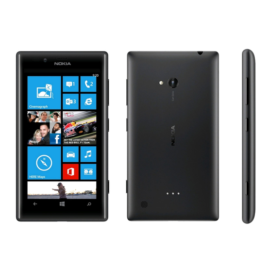
Nokia Lumia 720
RM-885
Key features
Sleek and stylish unibody design
Windows Phone 8 Operating System
4.3" IPS LCD display with Nokia ClearBlack technology
6.7 Mpix main camera with f/1.9 aperture
1.3 Mpix front camera
Bluetooth 3.0, NFC connectivity
Version 1.0
Exploded view
More
Assembly steps
More
Service devices
More
Phone reset
More
Disassembly steps
Assembly video
Product controls and interfaces
©2013 Nokia | Nokia Internal Use only | All Rights Reserved.
Check the repair
policy before
performing any
mechanical repair
on Service Level
1&2!
Disassembly video
More
Solder components
More
Service concept
More
More
More
More
Advertisement

Related Manuals for Nokia Lumia 720


Summary of Contents for Nokia Lumia 720
- Page 1 Disassembly steps Disassembly video More More More Assembly steps Assembly video Solder components More More More Service devices Product controls and interfaces Service concept More More More Phone reset More ©2013 Nokia | Nokia Internal Use only | All Rights Reserved.
-
Page 2: Exploded View
WLC FLEX I0029 BATTERY GASKET AV MODULE I0028 I0027 UNIBODY ASSEMBLY I0025 FLASH LED I0026 Only available Not reuseable Repair/swap v1.0 as assembly after removal only in level 3 ©2013 Nokia | Nokia Internal Use only | All Rights Reserved. -
Page 3: Disassembly Steps
Service Manual Level 1 and 2 Disassembly steps Nokia Lumia 720 RM-885 Version 1.0 1) For disassembling you need the Nokia Standard toolkit version 2. You will also need an AV plug and the SIM door key. 2) Protect the DISPLAY MODULE with protective film. - Page 4 3) Insert the SIM door key to the small hole on the SD DOOR and press it gently. Remove the SD DOOR. 4) Insert the SIM door key to the small hole on the SIM DOOR and press it gently. Remove the SIM DOOR.
- Page 5 5) Unscrew the TORX+ size 2 screw. Do not use it again. Discard it. 6) To release the DISPLAY MODULE insert the SRT-6 to the top left corner of the device and slide to the direction shown. Be careful not to damage the UNIBODY ASSEMBLY!
- Page 6 7) Push the top end of the UNIBODY ASSEMBLY to the direction shown to release the top part of the DISPLAY MODULE. 8) Release the left side of the UNIBODY ASSEMBLY by sliding the SRT-6 to the direction shown. Be careful not to damage the UNIBODY ASSEMBLY!
- Page 7 9) Release the four clips on the right side of the device with the SRT-6. Do not slide the SRT-6 as it might damage the SIDEKEY FLEX! 10) Lift the top end of the DISPLAY MODULE up first. The DISPLAY MODULE and the UNIBODY ASSEMBLY can now be separated.
- Page 8 11) Use the AV plug to lever up the AV MODULE. Remove the AV MODULE. 12) Lift one corner of the BATTERY GASKET with the SS-93 and peel it off. Do not use it again. Discard it.
- Page 9 13) Use the SS-93 to release the top end of the WLC FLEX. Be careful not to damage it! 14) Then release the middle part of the WLC FLEX. Be careful not to bend the flex!
- Page 10 15) Carefully release the bottom end of the WLC FLEX and remove it. Be careful not to damage the flex! 16) Use the SS-93 to release the FLASH LED. Remove it with tweezers.
- Page 11 17) Open the BATTERY connector with the SS-93. Be careful not to damage the connector or any components nearby! 18) Use the SS-93 to release the top parts of the HEATSPREADER. Be careful not to damage the BATTERY connector!
- Page 12 19) Peel off the HEATSPREADER completely. Do not use it again. Discard it. 20) Lift up the BATTERY with the SS-93 from the bottom end. Remove the BATTERY.
- Page 13 21) Unscrew the three Torx+ size 4 screws in the order shown. Do not use them again. Discard them. 22) Lift up and remove the MAIN ANTENNA.
- Page 14 23) Use the dental tool to lever up the IHF SPEAKER. Be careful not to injure yourself with the sharp end of the dental tool. The IHF SPEAKER is not reusable. Discard it. 24) Release also the IHF SPEAKER GASKET with the dental tool. Discard it.
- Page 15 25) Use the SRT-6 to release the top end of the RF COAX CABLE. Be very careful when opening the connector! Be also careful not to damage any components nearby! 26) Unscrew the four Torx+ size 4 screws in the order shown. Remove the screws with tweezers to avoid damaging the components on the ENGINE BOARD! Do not use these screws again.
- Page 16 27) Use the SS-93 to open the SIDEKEY FLEX connector. Be careful not to damage the connector or any components nearby! 28) Turn the ENGINE BOARD over as shown. Open the DISPLAY connector with the SS-93. Be careful not to damage the connector or any components nearby!
- Page 17 29) Open also the USB FLEX connector with the SS-93. Be careful not to damage the connector or any components nearby! 30) The ENGINE BOARD can now be separated.
- Page 18 31) Open the FRONT CAMERA connector with the SS-93 and remove it. Be careful not to damage the connector or any components nearby! 32) Open the CAMERA connector with the SS-93 and remove it. Be careful not to damage the connector or any components nearby!
- Page 19 33) Remove the CAMERA CONNECTOR GASKET with tweezers. Do not use it again. Discard it. 34) Remove the CAMERA BOOT.
- Page 20 35) Release the IC GASKET with the dental tool. Be careful not to damage the ENGINE BOARD! Do not use the IC GASKET again. 36) Lift up the RF COAX CABLE HOLDER with the RF COAX CABLE from the shown places.
- Page 21 37) Open the bottom end connector of the RF COAX CABLE with the SRT-6. Be very careful not to damage the connector or any components nearby! Remove the RF COAX CABLE and the RF COAX CABLE HOLDER. 38) Separate the RF COAX CABLE from the RF COAX CABLE HOLDER as shown.
- Page 22 39) Release the USB FLEX with the SS-93. Be careful not to damage the flex! Lift up and remove the USB FLEX. 40) Release the EARPIECE with the SS-93 and remove it with tweezers. Do not use it again. Discard it.
- Page 23 41) Remove the EARPIECE GASKET with the dental tool and discard it. 42) Remove the SIDEKEY FLEX with the SS-93. The SIDEKEY FLEX is not reusable. Discard it.
- Page 24 43) Remove the adhesive remains from the DISPLAY FRAME. 44) Use the dental tool to remove the FRONT CAMERA GASKET. Do not use it again. Discard it.
- Page 25 45) The Nokia Lumia 720 disassembly procedure is complete. -END OF DISASSEMBLY- ©2013 Nokia | Nokia Internal Use only | All Rights Reserved.
-
Page 26: Assembly Steps
Service Manual Level 1 and 2 Assembly steps Nokia Lumia 720 RM-885 Version 1.0 For assembling you need the Nokia Standard toolkit version 2. Remove the shown protective film from the SIDEKEY FLEX. Do not remove rest of the protective films yet. - Page 27 Place the SIDEKEY FLEX to the DISPLAY FRAME. Align the two shown SIDEKEY FLEX holes with the DISPLAY FRAME pins. Remove the remaining protective films. Lower down the bottom end of the SIDEKEY FLEX and align it with the shown pin.
- Page 28 Press the SIDEKEY FLEX for 5 seconds to activate the adhesive. Remove the shown protective film from the EARPIECE GASKET.
- Page 29 Place the EARPIECE GASKET to the DISPLAY FRAME. Press the EARPIECE GASKET to activate the adhesive. Remove the remaining protective film. Remove the EARPIECE from its package.
- Page 30 Place the EARPIECE to the DISPLAY FRAME. Note the alignment of the EARPIECE. Press the EARPIECE gently to activate the adhesive. Do not touch the center part of the EARPIECE! Bend the shown protective film of the FRONT CAMERA GASKET upwards. Then remove the other protective film.
- Page 31 Place the FRONT CAMERA GASKET to the DISPLAY FRAME and press it to activate the adhesive. Remove the protective film. Place the CAMERA BOOT to the ENGINE BOARD. Be careful not to damage any components on the ENGINE BOARD.
- Page 32 Remove the IC GASKET protective film. Place the IC GASKET to the ENGINE BOARD as shown.
- Page 33 Remove the CAMERA CONNECTOR GASKET protective film. Place the CAMERA CONNECTOR GASKET and align it with the shown edge. Bend the CAMERA flex slightly. Be careful not to damage the CAMERA flex!
- Page 34 Connect the CAMERA connector with the SS-93. Be careful not to damage the connector or any nearby components. Turn over the CAMERA and push it to its place. Connect the FRONT CAMERA connector with the SS-93. Be careful not to damage the connector or any nearby components.
- Page 35 Place the USB FLEX to the DISPLAY FRAME. Make sure the two shown guiding pins are aligned correctly. Press the USB FLEX gently with the SS-93 to activate the adhesive.
- Page 36 Place the bigger connector of the RF COAX CABLE on of top the shown connector and attach it by pressing gently with the SS-93. Be very careful not to damage the connector! Place the COAX CABLE HOLDER to its place.
- Page 37 Push the COAX CABLE to the COAX CABLE HOLDER as shown. Make sure that the COAX CABLE is correctly placed to the COAX CABLE HOLDER. Remove the PROXY SENSOR protective film.
- Page 38 Hold the ENGINE BOARD as shown and connect the DISPLAY connector. Be careful not to damage the connector or any nearby components! Connect also the USB connector. Be careful not to damage the connector or any nearby components!
- Page 39 Lower down the ENGINE BOARD and press it slightly. Use the SS-93 to push the PROXY SENSOR to its place. Connect the SIDEKEY FLEX connector with the SS-93. Be careful not to damage the connector or any nearby components!
- Page 40 Fasten the four TORX+ size 4 screws in the order shown to the torque of 13Ncm. Connect the RF COAX CABLE connector as shown. Be very careful not to damage the connector!
- Page 41 Place the IHF SPEAKER GASKET. Press it gently to activate the adhesive. Place the IHF SPEAKER. Note the alignment of the IHF SPEAKER. Press the IHF SPEAKER to its place.
- Page 42 Place the MAIN ANTENNA and press it gently. Fasten the three TORX+ size 4 screws in the order shown to the torque of 10Ncm.
- Page 43 Place the BATTERY top end first. Lower down and press the bottom end to lock the BATTERY into its place. Remove the shown protective film of the HEATSPREADER.
- Page 44 Place the HEATSPREADER on top of the BATTERY. Align the HEATSPREADER with the bottom end of the BATTERY as shown. Then align the top end of the HEATSPREADER with the shown corner of the ENGINE BOARD SHIELDING LID. While placing the HEATSPREADER, be careful not to damage the BATTERY connector! Press the HEATSPREADER to activate the adhesive and remove the protective film.
- Page 45 Connect the BATTERY CONNECTOR. Be careful not to damage the connector or any nearby components! Place the AV MODULE on the UNIBODY ASSEMBLY. Press the AV MODULE to lock it into its place.
- Page 46 Use the SS-93 to attach the AV MODULE flex. Check that the AV MODULE flex is aligned with the two pins. Place the FLASH LED and press it gently to activate the adhesive.
- Page 47 Remove the three protective films of the WLC FLEX. Place the top end of the WLC FLEX first and align the two shown holes of the flex with the UNIBODY ASSEMBLY. Be careful not to damage the flex while attaching it. Press the top end of the flex gently to activate the adhesive.
- Page 48 Place the bottom end of the WLC FLEX to its cavity and press it gently to activate the adhesive. At last, press the middle part of the WLC FLEX to activate the adhesive. Remove the BATTERY GASKET protective film.
- Page 49 Place the BATTERY GASKET on top of the WLC FLEX. Align the BATTERY GASKET to the center of the UNIBODY ASSEMBLY as shown. Remove the FLASH LED and the CAMERA protective films.
- Page 50 Place the bottom end of the DISPLAY MODULE to the UNIBODY ASSEMBLY first. Then lower down the top end. When lowering down the top end of the DISPLAY MODULE, note that the SIM DOOR button might be in the up position as shown. Use the SS-93 to push in the SIM DOOR button and insert the top end of the DISPLAY MODULE into the UNIBODY ASSEMBLY.
- Page 51 Press the DISPLAY MODULE from all sides to properly attach it to the UNIBODY ASSEMBLY. Push in the SD DOOR.
- Page 52 Fasten the TORX+ size 2 screw to the torque of 7Ncm. Push in the SIM DOOR.
- Page 53 Remove the DISPLAY protective film. Remove the UNIBODY ASSEMBLY protective film.
- Page 54 The Nokia Lumia 720 assembly procedure is complete. -END OF ASSEMBLY- ©2013 Nokia | Nokia Internal Use only | All Rights Reserved.
-
Page 55: Solder Components
BT/WLAN X6301 antenna spring NFC antenna X6500 spring X2100 connector Wireless charging X3302 connector NFC antenna X6501 grounding spring LED Flash X1403 connector LED Flash X1404 grounding GPS antenna X7720 spring v1.0 ©2013 Nokia | Confidential | All Rights Reserved. -
Page 56: Service Devices
For more information, refer to the Service Bulletin (SB-011) on Nokia Online. Supplier or manufacturer contacts for tool re-order can be found in “Recommended service equipment” document on Nokia Online. ©2013 Nokia | Nokia Internal Use only | All Rights Reserved. - Page 57 14 — Camera flash 15 — Volume keys 16 — Power/Lock key 17 — Camera key 18 — Wireless charging cover connector 19 — Loudspeaker 20 — Main antenna area v1.0 ©2013 Nokia | Nokia Internal Use only | All Rights Reserved.
- Page 58 Service Manual Level 1 and 2 Service concept Nokia Lumia 720 RM-885 Version 1.0 Flashing concept Service CA-101 software Note: Charged battery is man- datory Transceiver with embedded battery ©2013 Nokia | Nokia Internal Use only | All Rights Reserved.
-
Page 59: Phone Reset
Service Manual Level 1 and 2 Phone reset Nokia Lumia 720 RM-885 Version 1.0 Hardware reset If the phone hardware is jammed, you should first recommend that the consumer performs a hardware reset. The hardware reset does not reset the Windows Live ID or remove any consumer data. Because... - Page 60 Step 2 Input the following key combination: 1. Volume up 2. Volume down 3. Power 4. Volume down Step 3 The phone will reset and boot up automatically ©2013 Nokia | Nokia Internal Use only | All Rights Reserved.
-
Page 61: Version History
Service Manual Level 1 and 2 Version history Nokia Lumia 720 RM-885 Version 1.0 Version Date Description 26.02.2013 First published version ©2013 Nokia | Nokia Internal Use only | All Rights Reserved. - Page 62 www.s-manuals.com...
Need help?
Do you have a question about the Lumia 720 and is the answer not in the manual?
Questions and answers