Table of Contents

Related Manuals for GO-DEVIL Surface Drive

Summary of Contents for GO-DEVIL Surface Drive
- Page 1 ― INSTRUCTIONS ― Operation and Service Manual July 2011 GO-DEVIL ® Manufacturers of Louisiana, INC. (225) 752-0167 • Toll Free 1-888-490-3254 • Fax (225) 752-0175 18649 Womack Road • Baton Rouge, LA 70817 Please visit our website at www.godevil.com...
-
Page 2: Surface Drive Safety
• KEEP YOUR SURFACE DRIVE IN SAFE CONDITION. It is important to keep your engine properly maintained. Having a breakdown can be difficult, especially if you are far away from help or land. To help avoid problems, inspect your engine before each use and... -
Page 3: Table Of Contents
• Checking Belt Tension................14 • Adjusting Belt Tension, Replacing belt............. 15 SPECIAL TOOLS TO SERVICE SURFACE DRIVES…………………………….16 PROPELLER REMOVAL AND INSTALLATION………………………………….17 LOWER SEAL REPLACEMENT……………………………………………………17 SHAFT REMOVAL AND INSTALLATION…………………………………………18 BUSHING REMOVAL AND INSTALLATION……………………………………...19 SURFACE DRIVE PROP SHAFT DRIVE ASSEMBLY…………………………...20 SURFACE DRIVE SEAL INSTALLATION………………………………………..21 WARRANTY... -
Page 4: Assembly And Boat Setup
You have just purchased one of the toughest pieces of marine equipment ever built. The GO-DEVIL Surface Drive will give you many years of service with very little maintenance. Of the few problems that occur, most are due to dirty fuel or not running the engine out of fuel at the end of the season. - Page 5 The 3/8”x 2-1/2” bolt indicated by the arrow in the figure below is the pivot point for the Adjustable/Floating handle. Remove the bolt and insert the handle into the engine-mounted handle bracket. Reinstall the bolt into the bracket, passing it through the hole at the end of the handle.
- Page 6 35 HP Vanguard Kohler 27 HP Vanguard 23 HP Check to ensure that the throttle linkage on the engine moves throughout its full range when the throttle lever is depressed and that it returns to the idle position when released. For added safety, a stainless steel throttle return spring has been installed during factory assembly.
-
Page 7: Bolting Engine To Transom
Devil boats, the engine should be bolted to the transom using the two top holes. Tie a rope to the rib in your boat under the hand grip of the Surface Drive and put a loop in the rope. Slip the loop over the handle to hold the engine in a neutral position while the handle is in its lowest position. - Page 8 This procedure will hold your boat as tight as any boat strap and will secure your Surface Drive so it will not bounce when trailering. We also recommend that you tie a red flag to the tail end of the Surface Drive when towing your boat down the highway.
-
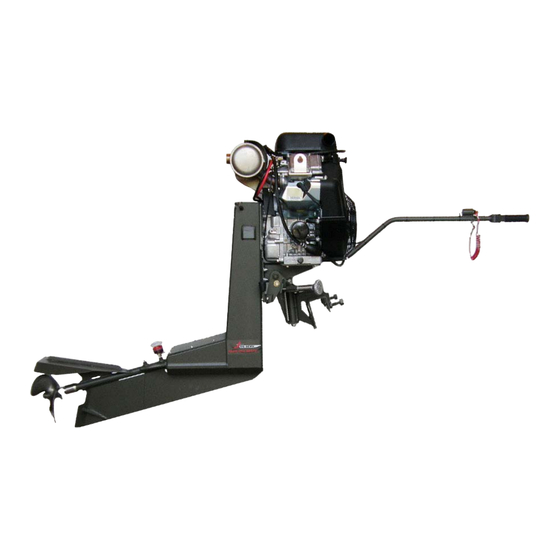
Page 9: Operation Instructions
OPERATION INSTRUCTIONS Surface Drive Features Adjustable/Floating Handle Industrial Engine Squeeze Throttle Access Panels Pressure Hand Grip Lubricator Kill Switch Manual Trim Knob Cavitation Plate Transom Clamp EZ Trim Lever Skeg Trim Tabs ENGINE OIL Fill the engine crankcase with the recommended amount and type of oil. With the engine held perfectly level, check the oil level with the dip stick. -
Page 10: Launching, Engine Starting
BASIC OPERATION Launching When launching your boat always leave the handle rope secured in the neutral position (shaft horizontal). This also applies when starting the engine. Before starting the engine on the water, always put on your life vest as you would in any boat with any engine. -
Page 11: Low Speed Operation
Get used to low speed maneuvering and docking the boat before attempting to increase speed. For the first time operating your new Surface Drive engine, turn the trim adjustment knob counterclockwise until the prop and cavitation plate can be fully submerged while the boat is floating at rest. - Page 12 EZ Trim Lever to drop your prop height. After getting on plane and you are in a sufficient water depth, push down on the Surface Drive handle again and flip the EZ Trim Lever back up to come back to your normal trim height.
-
Page 13: Lubrication
EXTERNAL GREASE FITTINGS The Surface Drive unit has 3 external grease fittings which require periodic lubrication. One fitting is located on the drive tube and the other two are located on the tilt axis and steering axis (see photos below). -
Page 14: Pressure Lubrication
PRESSURE LUBRICATION A pressure lubricator shown on the previous page is mounted on the upper end of the drive tube and features a spring loaded piston which creates a small amount of grease pressure inside the drive tube. This grease volume lubricates the prop shaft, lower bronze bushing, and lower seals. -
Page 15: Internal Drive Lubrication
INTERNAL DRIVE LUBRICATION The Surface Drive unit has internal grease fittings located within the frame housing. One fitting is located on each of the two universal joints and also on both the upper bearing housing supporting the prop shaft and on the sprocket shaft bearing housing shown in the photo below. -
Page 16: Belt Tension And Installation
Force and deflection on Surface Drive Engines should be kept within the tolerance listed below. Belts that are run too loose will cause an increase in driveline vibration resulting in reduced belt life. -
Page 17: Checking Belt Tension
CHECKING BELT TENSION Checking Belt Tension on the Surface Drive does not require removal of the rear access panels. An inspection hole on the side of the frame is provided to inspect and check belt tension from outside of the frame. -
Page 18: Adjusting Belt Tension, Replacing Belt
ADJUSTING BELT TENSION REMOVE UPPER ACCESS PANEL: Remove all ¼” bolts holding the Upper access panel with a 3/8” socket and ratchet. The panel is sealed with Loctite 598 High Performance RTV Silicone Gasket Maker. The panel will need to be pried from the frame with a large screwdriver. -
Page 19: Special Tools To Service Surface Drives
prevent water leakage. Install the Upper Access Panel and lightly tighten the ¼” bolts. Allow Silicone to cure for several hours and then torque all bolts to 125 In.-Lbs. (10 Ft.-Lbs.) TOOLS SPECIAL TOOLS TO SERVICE SURFACE DRIVES PART # DESCRIPTION USED FOR PRICE... -
Page 20: Propeller Removal And Installation
PROPELLER REMOVAL Using a 1 7/16” wrench, hold back on the forward jam nut (1A1-78)and remove the rear nylon insert nut (1A4-78) with a 1 1/4” wrench. Using a prop wrench (PW2-3BL) unscrew the prop. If prop wrench is not available, use a large pipe wrench with the sides of the jaws touching the end of the propeller blades to unscrew the prop. -
Page 21: Shaft Removal And Installation
Install the new scraper seal (78SC) into the lower housing cap (LHC-78) and install onto the lower seal housing (LSHS-15) by turning it counter-clockwise (left-hand threads). Install the propeller as shown on PAGE 17. SHAFT REMOVAL Leave the engine mounted on your boat in the trailering position or clamped to a solid saw horse. -
Page 22: Bushing Removal And Installation
BUSHING REMOVAL AND INSTALLATION WITH OUR TOOLS 1. Using the 1” tap, screw it into the bushing. This will cut threads in the bushing to fit the bushing puller (#BUPU). 2. Screw the bushing puller (#BUPU) into the bushing. Screw the shaft puller (#SHBUPU) into the bushing puller. - Page 26 This warranty replaces any warranties before August 1, 2011 Go-Devil Manufacturers of Louisiana, Inc. will repair or replace any components, on the Go-Devil drive unit that we manufacture at no charge for a period of two years that are defective in materials or workmanship. Transportation charges on parts submitted for repair or replacement under this warranty must be borne by the owner of the unit.
Need help?
Do you have a question about the Surface Drive and is the answer not in the manual?
Questions and answers