Table of Contents
Advertisement
Advertisement
Table of Contents
Troubleshooting

Related Manuals for Haulotte Group 3632T


Summary of Contents for Haulotte Group 3632T
- Page 1 OPERATOR’S & MAINTENANCE MANUAL B33-01-0089 Rev 4 May 2013...
- Page 2 Repair or replace all damaged or malfunctioning components. Haulotte Group is dedicated to the continuous improvement of this and all Haulotte Group products. Therefore, equipment information is subject to change without notice. Direct any questions or concerns regarding errors and / or discrepancies in this manual to the Haulotte Group Customer Service Department: at 1-800-537-0540 or visit Haulotte Group online at www.haulotte-usa.com.
-
Page 3: Table Of Contents
HAULOTTE GROUP 1 SAFETY TABLE OF CONTENTS 1 SAFETY LEGEND: SAFETY ADVISORIES....................7 BEFORE OPERATION........................8 DURING OPERATION ........................9 FALL PROTECTION ........................11 MANUAL FORCE .......................... 11 WIND LOADING..........................12 EXPLOSION HAZARD ........................12 MAINTENANCE ..........................13 2 SPECIFICATIONS .......................... 15 RANGE OF MOTION ........................ - Page 4 HAULOTTE GROUP 1 SAFETY 7 OPTIONAL EQUIPMENT.........................91 DRIVE AND SET........................... 92 MATERIAL LIFT HOOK ........................ 95 PLATFORM ROTATOR ........................ 98 8 MATERIAL SAFETY ........................99 LEAD ACID BATTERIES, WET, FILLED WITH ACID – UN 2794 ..........99 POWERFLOW™ AW HVI HYDRAULIC OIL ................104 9 AXLE AND RELATED COMPONENTS ..................111...
- Page 5 HAULOTTE GROUP 1 SAFETY LIST OF ILLUSTRATIONS Figure 2-1. Range of Motion....................... 15 Figure 3-1. Ground Control Panel ...................... 22 Figure 3-2. Platform Control Panel..................... 24 Figure 3-3. Boom Travel Latch......................26 Figure 3-4. Platform Travel Latch....................... 27 Figure 3-5. Platform Locking Pins ...................... 27 Figure 3-6.
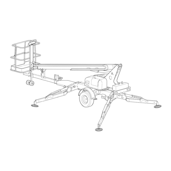
- Page 6 HAULOTTE GROUP 1 SAFETY PRIMARY MACHINE COMPONENTS SLAVE CYLINDER PLATFORM EXTENSION TUBE TELESCOPIC BOOM LIFT CYLINDER TURNTABLE MASTER CYLINDER GENERATOR INTERFACE PLATE OUTRIGGER CYLINDER OUTRIGGER OUTRIGGER FOOT OUTRIGGER AXLE FOOT PAD BOOM REST COUPLER LATCH RELEASE JACK HANDLE TRAILER DOLLY...
-
Page 7: Safety
HAULOTTE GROUP 1 SAFETY 1 SAFETY Proper training is required for the safe operation of any mechanical device. Failure to follow all instructions and safety precautions in this manual and attached to the aerial work platform will result in death or personal injury. -
Page 8: Before Operation
Keep loose clothing, jewelry, gloves and hair away from moving parts. ALWAYS wear a Safety Harness and energy-absorbing Lanyard, such as the Safety Harness and Lanyard available through the Haulotte Group. ALWAYS inspect platform floor and outrigger footpads for mud, grease, debris or other foreign material. -
Page 9: During Operation
HAULOTTE GROUP 1 SAFETY DURING OPERATION Ensure the following general safety precautions are followed while operating the aerial work platform: ALWAYS position away from power lines, this ensures that no part of the aerial work platform accidentally reaches into an unsafe area. This includes full extension of the telescoping boom through 700º... - Page 10 HAULOTTE GROUP 1 SAFETY DURING OPERATION (CONTINUED) ALWAYS use a three (3) point contact (both hands and one foot) when entering or exiting the work platform. ALWAYS wear proper footgear. ALWAYS keep the platform free of debris. ALWAYS keep personnel and obstructions clear of the aerial work platform when repositioning the boom or platform.
-
Page 11: Fall Protection
NEVER exceed the load limits set by the manufacturer / factory. Use only the material lifting hook, supplied as an option and manufactured by Haulotte Group when lifting materials. Safely stow all tools and equipment. NEVER exceed load ratings by transferring loads to the aerial work platform at elevated heights. -
Page 12: Wind Loading
HAULOTTE GROUP 1 SAFETY WIND LOADING NEVER operate the aerial work platform in strong or winds that exceed 28 mph (12.5 m/s) or 45 km/h). NEVER increase the surface area of the platform or the load. Increasing the area exposed to the wind will decrease the aerial work platform stability. -
Page 13: Maintenance
ALWAYS consult an authorized Haulotte Group technician by contacting the Customer Service Department: at 1-800-537-0540 if repairs are necessary. NEVER modify, alter or change the aerial work platform without first consulting an authorized Haulotte Group technician, and NEVER in any way that would affect its original design or operation. - Page 14 HAULOTTE GROUP 1 SAFETY MAINTENANCE SAFETY (CONTINUED) Battery Maintenance Ensure the following general safety precautions are followed when performing battery maintenance on the aerial work platform: ALWAYS check the battery fluid level daily. ALWAYS wear safety glasses when working with or near batteries.
-
Page 15: Specifications
HAULOTTE GROUP 2 SPECIFICATIONS 2 SPECIFICATIONS The following information is based on ideal working conditions. Machine performance may vary based on work environment and on machine options. Only one boom function is permitted at a time, this function is only operable as long as the boom is within the safe operating zone. -
Page 16: Specifications
HAULOTTE GROUP 2 SPECIFICATIONS SPECIFICATIONS Serial Number __________________________ 43 ft 6 in (13.4 m) Maximum Working Height 37 ft 6 in (11.4 m) Maximum Platform Height Maximum Horizontal Outreach From Centerline 32 ft (9.8 m) From Outrigger Footpad Edge 27 ft (8.2 m) - Page 17 HAULOTTE GROUP 2 SPECIFICATIONS SPECIFICATIONS (CONTINUED) 3,000 psi (207 bar) (20,684 kPa) Hydraulic Pressure 4.8 Gallons (18.2 L) Reservoir Capacity 7.0 Gallons (26.5 L) Hydraulic System Capacity HVI AW32 Hydraulic Oil (Standard) Maximum Decibel Level DC Mode – Ground (Lower) 60 dBA DC Mode –...
-
Page 18: Warranty - New Product; Haulotte North America
HAULOTTE GROUP 2 SPECIFICATIONS WARRANTY - NEW PRODUCT; HAULOTTE NORTH AMERICA Haulotte US Inc (Haulotte) warrants its new products made by it to be free from defects in material or workmanship for twelve (12) months under normal operational conditions from the warranty start date (delivery date). -
Page 19: Warranty Claims Procedure
Haulotte Group|BilJax to return warranty parts at the time the parts order is placed. 3) Replacement parts will then be sent by Haulotte Group|BilJax to the dealer or distributor. All parts are invoiced at dealer|distributor list price. -
Page 20: Damaged Equipment Policy
DAMAGED EQUIPMENT POLICY Safety Statement At Haulotte Group we are dedicated to the safety of all users of our products. All Haulotte Group aerial work platforms are designed, manufactured and tested to comply with current applicable ANSI, CSA, AS and / or CE Standards and regulations. -
Page 21: Operation
3 OPERATION 3 OPERATION The 3632T / HTT 13 Telescoping Boom Lift is a Summit Series™ trailer-mounted aerial work platform, designed and manufactured to position personnel with their tools and equipment at overhead work locations. The platform load capacity is rated at 500 pounds (227 kilograms). During all aerial work platform operations, four extended outriggers support the unit. -
Page 22: Ground (Lower) Control Panel
HAULOTTE GROUP 3 OPERATION GROUND (LOWER) CONTROL PANEL The ground (lower) control panel is used to operate outriggers and all boom functions. To access the ground (lower) control panel, open the control panel access cover found on the turntable. The ground (lower) control panel includes the following controls and indicators. Refer to Figure 3-1. - Page 23 HAULOTTE GROUP 3 OPERATION GROUND (LOWER) CONTROL PANEL (CONTINUED) Display Panel is a lighted text window that displays the current operating status or an DISPLAY PANEL existing error condition when the (1) is positioned at either (1a) or (1b). KEY SWITCH...
-
Page 24: Platform (Upper) Control Panel
HAULOTTE GROUP 3 OPERATION PLATFORM (UPPER) CONTROL PANEL The platform (upper) control panel is used to control all boom functions. The platform (upper) control panel is activated by turning the (1) on the ground (lower) control panel, clockwise to the KEY SWITCH (1b) icon. - Page 25 HAULOTTE GROUP 3 OPERATION PLATFORM (UPPER) CONTROL PANEL TELESCOPIC (CONTINUED) Battery Condition Indicator Indicator LEDs light up to indicate the level of charge in the batteries. A lighted green LED indicates an adequate charge level. A lighted yellow LED indicates the need for charging soon.
-
Page 26: Normal Operating Procedure
Become familiar with the location and function of all controls. Learn to smoothly START STOP boom functions. Perform the following procedures to operate the Haulotte Group Telescoping Boom Lift. Read and obey all safety precautions and operating instructions, as well as all Federal, State, and Local codes and regulations. -
Page 27: Figure 3-4. Platform Travel Latch
HAULOTTE GROUP 3 OPERATION NORMAL OPERATING PROCEDURE (CONTINUED) Release the by lifting up on the handle, and pivoting the platform PLATFORM TRAVEL LATCH upright. Refer to Figure 3-4. Lift up on PLATFORM TRAVEL to release LATCH Platform. Figure 3-4. Platform Travel Latch ... -
Page 28: Figure 3-6. Outrigger Controls
HAULOTTE GROUP 3 OPERATION NORMAL OPERATING PROCEDURE (CONTINUED) At the ground (lower) control panel, turn the (1) counter clockwise to the KEY SWITCH GROUND (1a) icon. If power does not come on, make sure that both of the CONTROLS EMERGENCY STOP buttons;... - Page 29 HAULOTTE GROUP 3 OPERATION NORMAL OPERATING PROCEDURE (CONTINUED) Use the ground (lower) control panel to operate the boom lift functions. Raise, lower, extend and rotate the boom by pressing (pushing) and holding the desired and function buttons at the SPEED same time.
-
Page 30: Manual Boom Operation
HAULOTTE GROUP 3 OPERATION MANUAL BOOM OPERATION Manual retraction, rotation and lowering functions allow the boom to be moved and lowered during hydraulic power interruption or failure. The following procedures for manual retraction, rotation and lowering require a person on the ground to operate the manual controls and hand pump. -
Page 31: Figure 3-8. Manual Boom Lowering Valve
HAULOTTE GROUP 3 OPERATION MANUAL BOOM OPERATION (CONTINUED) Manual Boom Lowering Procedure The lift cylinder is equipped with a ; this valve is found at the base of the lift MANUAL LOWERING VALVE cylinder. Use the to lower the platform in case of a complete electrical power failure, a VALVE HANDLE load shift, or any other emergency. -
Page 32: Towing The Aerial Work Platform
HAULOTTE GROUP 3 OPERATION TOWING THE AERIAL WORK PLATFORM The aerial work platform trailer includes a single axle, two-inch ball hitch, hydraulic surge brakes, mechanical parking brake, safety chains, brake lights and side marker lights. Proper aerial work platform transport requires the proper attachment and inspection of these components before towing. -
Page 33: Figure 3-9. Trailer Hitching
HAULOTTE GROUP 3 OPERATION TOWING THE AERIAL WORK PLATFORM (CONTINUED) Procedure to hitch and tow the aerial work platform. Back the tow vehicle to the trailer. Verify that the ball and hitch are aligned and that the trailer hitch has proper clearance above the ball. Refer to Figure 3-9. -
Page 34: Lifting The Aerial Work Platform
HAULOTTE GROUP 3 OPERATION LIFTING THE AERIAL WORK PLATFORM Refer to Figure 3-10. Completely retract and lower the telescoping boom. Secure both boom travel latches (A). Remove all loose materials from machine. Retract all outrigger cylinders to the fully “stowed” (upright) position. -
Page 35: Transporting The Aerial Work Platform On A Truck Bed
HAULOTTE GROUP 3 OPERATION TRANSPORTING THE AERIAL WORK PLATFORM ON A TRUCK BED Refer to Figure 3-11. Verify that the truck or trailer is parked on a firm and level surface. Completely retract and lower the boom into the “stowed” position. - Page 36 HAULOTTE GROUP 3 OPERATION...
-
Page 37: Equipment Maintenance
Refer to it when inspecting this machine. It is the practice of Haulotte Group to issue Service and / or Safety Bulletins, which may include updates to the information contained in this manual. In such instances, procedures contained in Haulotte Group Service Bulletins or Safety Bulletins supersede the information contained in manual. -
Page 38: Battery Recharge
HAULOTTE GROUP 4 EQUIPMENT MAINTENANCE BATTERY RECHARGE Recharge aerial work platform batteries after each 8-hour work shift or as needed. When the aerial work platform is not in use, batteries should be recharged at least once per week. Under normal circumstances, battery recharge should take approximately 10-12 hours. -
Page 39: Battery Fault Codes
HAULOTTE GROUP 4 EQUIPMENT MAINTENANCE BATTERY RECHARGE (CONTINUED) If a Battery fault is detected, a fault code will appear on the display. The red CHARGE CURRENT indicator LED will become lit. Refer to Table ?-1 for battery charger fault codes. -
Page 40: Daily Service Checks
HAULOTTE GROUP 4 EQUIPMENT MAINTENANCE DAILY SERVICE CHECKS The following Maintenance Procedures should be performed daily or before each operation: Verify that all decals are legible, correctly applied, and in plain view. Refer to the “Decal Replacement” section of this manual for decal locations. -
Page 41: Figure 4-2. Outrigger Position Switch
HAULOTTE GROUP 4 EQUIPMENT MAINTENANCE DAILY SERVICE CHECKS (CONTINUED) Verify that outrigger safety interlocks operate correctly. Begin with the outriggers fully extended and the aerial work platform level. Raise one outrigger until the footpad is not in contact with the ground. -
Page 42: Figure 4-3. Hydraulic Reservoir
HAULOTTE GROUP 4 EQUIPMENT MAINTENANCE DAILY SERVICE CHECKS (CONTINUED) Inspect hydraulic System and fluid levels. Check all hydraulic hoses and fittings for leaks and / or damage. Tighten or replace as necessary to prevent hydraulic oil or pressure loss. -
Page 43: Weekly Service Checks
HAULOTTE GROUP 4 EQUIPMENT MAINTENANCE WEEKLY SERVICE CHECKS Perform the following service checks at least once each week in addition to all recommended Daily Service Checks: Check Battery Electrolyte level. If battery charge is low, add enough water to bring the electrolyte level to the top of the plates. -
Page 44: Monthly Service Checks
HAULOTTE GROUP 4 EQUIPMENT MAINTENANCE MONTHLY SERVICE CHECKS Perform the following service checks at least once each month: Check battery for loose connections or damaged wires. Clean all battery terminals. Verify proper operation of manual lowering valves and hand pump. -
Page 45: Annual Service Checks
HAULOTTE GROUP 4 EQUIPMENT MAINTENANCE ANNUAL SERVICE CHECKS Perform the following service checks at least once each year: Replace Hydraulic Oil and Oil Filter. Wipe away dirt and excess oil from the area around the power unit, hoses and filter(s) using cleaning cloths and alcohol solvent. -
Page 46: Figure 4-6. Machine Position For Slew Ring Measurement
If the difference in measurements is greater than 0.25 in (6.35 mm) the slew ring bearing should be replaced. Contact Haulotte Group Customer Service Department: at 1-800-537- 0540 or visit Haulotte Group online at www.haulotte-usa.com for additional information. Figure 4-8. Platform Position after Rotation... -
Page 47: Structural Inspection
HAULOTTE GROUP 4 EQUIPMENT MAINTENANCE STRUCTURAL INSPECTION A comprehensive structural inspection of the unit shall be performed under any of the following conditions: Ten years from the date of manufacture and every five years thereafter. After any actual, suspected or potential damage is sustained that could affect the structural integrity or stability of the aerial work platform. -
Page 48: Leveling System Calibration Procedure
HAULOTTE GROUP 4 EQUIPMENT MAINTENANCE LEVELING SYSTEM CALIBRATION PROCEDURE Machine Leveling Instructions Deploy all of the outriggers, and slightly raise the base of the machine to position it for leveling. Refer to Figure 4-9. Place a small, standard “level” on the base of the turntable (Level Placement Option A). If a small “level”... -
Page 49: Figure 4-12. Ground (Lower) Control Panel For Leveling System
HAULOTTE GROUP 4 EQUIPMENT MAINTENANCE LEVELING SYSTEM CALIBRATION PROCEDURE (CONTINUED) Ground (Lower) Control Box Calibration Instructions Use the ground (lower) control panel to access the control box maintenance menu. Refer to Figure 4-12. 1 1A 4A & B Figure 4-12. Ground (Lower) Control Panel for Leveling System... -
Page 50: Overload Protection Calibration Procedure
HAULOTTE GROUP 4 EQUIPMENT MAINTENANCE OVERLOAD PROTECTION CALIBRATION PROCEDURE Load Sense Zeroing 1) Remove the securing the to the , allowing CLEVIS PIN PLATFORM PLATFORM MOUNTING BRACKET to pivot about the and rest on the ground. This removes the load... - Page 51 HAULOTTE GROUP 4 EQUIPMENT MAINTENANCE OVERLOAD PROTECTION CALIBRATION PROCEDURE (CONTINUED) 5) Scroll through the maintenance menu using the (7) button to scroll down, use the TURTLE RABBIT (8) button to scroll back up, until “LOAD SENSE ZERO CALIBRATION UTILITY” is displayed in (3).
- Page 52 The Ratio should be within 3.50:1 to 4.00:1. If so, continue on to Step 11. If the ratio is not within the above values, contact Haulotte Group Customer Service Department: at 1-800-537-0540 or visit Haulotte Group online at www.haulotte-usa.com...
-
Page 53: Additional Service Information
HAULOTTE GROUP 4 EQUIPMENT MAINTENANCE ADDITIONAL SERVICE INFORMATION Seals on hydraulic cylinders should be replaced every five years or as indicated by aerial work platform performance. All service checks should be performed on an aerial work platform that has been stored without use for a period exceeding thirty (30) days. -
Page 54: Manual Outrigger Retraction
HAULOTTE GROUP 4 EQUIPMENT MAINTENANCE MANUAL OUTRIGGER RETRACTION The Manual Outrigger Retraction procedure allows the outriggers to be retracted into the “stowed” (upright) position during hydraulic power interruption or power failure. The Manual Outrigger Control Kit, Part Number: A-00819, including a wire harness, is required to perform this manual procedure. -
Page 55: Hydraulic Pressure Gauge
HAULOTTE GROUP 4 EQUIPMENT MAINTENANCE HYDRAULIC PRESSURE GAUGE The Hydraulic Pressure Gauge Part Number B02-16-0020 is used to measure the aerial work platform’s system pressure. It is used as a diagnostic tool when the Boom is NOT performing as expected. -
Page 56: Troubleshooting
TROUBLESHOOTING Refer to the following Table for basic Troubleshooting Operations. Additional information can be found in the Haulotte Group Parts and Service Manual. Contact the Haulotte Group Service Department with any questions or before attempting any advanced troubleshooting operations. TABLE 4-2. TROUBLE SHOOTING... -
Page 57: Error Code Definitions - Controls
HAULOTTE GROUP 4 EQUIPMENT MAINTENANCE ERROR CODE DEFINITIONS – CONTROLS The DISPLAY PANEL located on the ground control panel indicates the present operating status of the aerial work platform. If an error condition is detected, the appropriate error code will be displayed on this panel. - Page 58 HAULOTTE GROUP 4 EQUIPMENT MAINTENANCE TABLE 4-3 ERROR CODE DEFINITIONS ERROR MESSAGE ERROR DEFINITION TO SIMULATE ERROR TO CLEAR ERROR COMMENTS 014 CHECK ENGINE Engine had low oil Kawasaki Engine: While This is a latched error. X-Boom Machines with LOW OIL...
- Page 59 HAULOTTE GROUP 4 EQUIPMENT MAINTENANCE TABLE 4-3 ERROR CODE DEFINITIONS ERROR MESSAGE ERROR DEFINITION TO SIMULATE ERROR TO CLEAR ERROR COMMENTS 028 SHORTED CIRCUIT Excessive load was Use a piece of wire to This is a latched error. Checked only at...
- Page 60 HAULOTTE GROUP 4 EQUIPMENT MAINTENANCE TABLE 4-3 ERROR CODE DEFINITIONS ERROR MESSAGE ERROR DEFINITION TO SIMULATE ERROR TO CLEAR ERROR COMMENTS 044 SHORTED CIRCUIT Excessive load was Use a piece of wire to This is a latched error. Checked only at...
- Page 61 HAULOTTE GROUP 4 EQUIPMENT MAINTENANCE TABLE 4-3 ERROR CODE DEFINITIONS ERROR MESSAGE ERROR DEFINITION TO SIMULATE ERROR TO CLEAR ERROR COMMENTS 059 OPEN CIRCUIT A load of less than 70mA Disconnect a wire from This is a latched error. Checked only at...
- Page 62 HAULOTTE GROUP 4 EQUIPMENT MAINTENANCE TABLE 4-3 ERROR CODE DEFINITIONS ERROR MESSAGE ERROR DEFINITION TO SIMULATE ERROR TO CLEAR ERROR COMMENTS 074 SHORTED CIRCUIT Excessive load was Use a piece of wire to This is a latched error. Not Used...
- Page 63 HAULOTTE GROUP 4 EQUIPMENT MAINTENANCE TABLE 4-3 ERROR CODE DEFINITIONS ERROR MESSAGE ERROR DEFINITION TO SIMULATE ERROR TO CLEAR ERROR COMMENTS 089 OPEN CIRCUIT A load of less than 70mA Disconnect a wire from This is a latched error. Checked only at...
- Page 64 HAULOTTE GROUP 4 EQUIPMENT MAINTENANCE TABLE 4-3 ERROR CODE DEFINITIONS ERROR MESSAGE ERROR DEFINITION TO SIMULATE ERROR TO CLEAR ERROR COMMENTS 104 OUTREACH Boom has reached Put 500lbs in boom, level This is a self clearing Machines with Moment AT MAXIMUM...
- Page 65 HAULOTTE GROUP 4 EQUIPMENT MAINTENANCE TABLE 4-3 ERROR CODE DEFINITIONS ERROR MESSAGE ERROR DEFINITION TO SIMULATE ERROR TO CLEAR ERROR COMMENTS 129 OPEN CIRCUIT A load of less than 70mA Disconnect a wire from This is a latched error. Checked only at...
- Page 66 HAULOTTE GROUP 4 EQUIPMENT MAINTENANCE TABLE 4-3 ERROR CODE DEFINITIONS ERROR MESSAGE ERROR DEFINITION TO SIMULATE ERROR TO CLEAR ERROR COMMENTS 144 SHORTED CIRCUIT Excessive load was Use a piece of wire to This is a latched error. Checked only at...
- Page 67 HAULOTTE GROUP 4 EQUIPMENT MAINTENANCE TABLE 4-3 ERROR CODE DEFINITIONS ERROR MESSAGE ERROR DEFINITION TO SIMULATE ERROR TO CLEAR ERROR COMMENTS 159 OPEN CIRCUIT A load of less than 70mA Disconnect a wire from This is a latched error. Checked only at...
-
Page 68: Error Code Definitions - Motor Controller
HAULOTTE GROUP 4 EQUIPMENT MAINTENANCE ERROR CODE DEFINITIONS – MOTOR CONTROLLER The Motor Controller, located under the left power (driver side) compartment cover (behind the lower control box), indicates the operational status of the controller. If an error condition is detected, the appropriate error code will be displayed by a flashing indicator light. - Page 69 HAULOTTE GROUP 4 EQUIPMENT MAINTENANCE TABLE 4-4. ERROR CODE DEFINITIONS - MOTOR CONTROLLER FLASH PRIORITY ID FAULT DESCRIPTION SOLUTION FAULT Motor Open Circuit Pump motor cable disconnected. Check pump-motor and controller cables. Measure pump motor resistance it should be near zero ohms.
- Page 70 HAULOTTE GROUP 4 EQUIPMENT MAINTENANCE...
-
Page 71: Cylinder Replacement
Perform all maintenance procedures only in an area that is well-lit and well-ventilated. Haulotte Group is not responsible for personal injury or property damage resulting from the improper use of equipment or failure to follow all procedures and related safety precautions. -
Page 72: Figure 5-2. Location Of Slave Cylinder
HAULOTTE GROUP 5 CYLINDER REPLACEMENT MASTER / SLAVE CYLINDER REPLACEMENT (CONTINUED) Master Cylinder (Continued) Place absorbent cloths below the cylinder ports and detach hydraulic hoses from the cylinder. Elevate hoses to prevent leakage. Plug or cap exposed hose fittings and cylinder ports. -
Page 73: Lift Cylinder Replacement
HAULOTTE GROUP 5 CYLINDER REPLACEMENT LIFT CYLINDER REPLACEMENT 55XA / HLA 19 PX Aerial Work Platforms have three (3) lift cylinders, use the following procedure to remove and replace faulty or damaged hydraulic cylinders. Refer to Figure 5–3 for the location of these cylinders. - Page 74 HAULOTTE GROUP 5 CYLINDER REPLACEMENT LIFT CYLINDER REPLACEMENT (CONTINUED) Verify that the cylinder is supported by lifting straps and an overhead hoist or equivalent. Remove the pivot pin using a hammer and a brass or hardwood drift. ...
-
Page 75: Outrigger Cylinder Replacement
HAULOTTE GROUP 5 CYLINDER REPLACEMENT OUTRIGGER CYLINDER REPLACEMENT Use the following procedure to remove and replace faulty or damaged hydraulic cylinders on the outriggers: Lower the outrigger until the footpad is touching the ground. DO NOT transfer the weight of the aerial work platform onto the outrigger. - Page 76 HAULOTTE GROUP 5 CYLINDER REPLACEMENT OUTRIGGER CYLINDER REPLACEMENT (CONTINUED) At the base of the cylinder, unbolt and remove the pin retainer from each side of the pivot pin. Remove the pivot pin using a hammer and a brass or hardwood drift.
-
Page 77: Decal Replacement
HAULOTTE GROUP 6 DECAL REPLACEMENT 6 DECAL REPLACEMENT WARNING Decals contain information that is required for the safe and proper use of the aerial work platform. Decals should be considered necessary components of the machine and should be checked before each use to verify that they are correctly attached and legible. -
Page 78: Decal Replacement - Decal Kit - Ansi
HAULOTTE GROUP 6 DECAL REPLACEMENT DECAL REPLACEMENT – DECAL KIT - ANSI... - Page 79 Decal – Notice Lanyard Attachment 0202-0523 Decal - Flag, Made In USA B06-00-0476 Decal - Notice - Range of Motion - 3632T / HTT 13 B06-00-0474 Decal - Notice - Platform Maximum Load B06-00-0491 Decal - Warning - Platform Operation - 3632T / HTT 13...
-
Page 80: Decal Replacement - Identification Plates & Optional Equipment Ansi
HAULOTTE GROUP 6 DECAL REPLACEMENT DECAL REPLACEMENT – IDENTIFICATION PLATES & OPTIONAL EQUIPMENT ANSI... - Page 81 HAULOTTE GROUP 6 DECAL REPLACEMENT DECAL REPLACEMENT – IDENTIFICATION PLATES & OPTIONAL EQUIPMENT ANSI IDENTIFICATION PLATES (Used on all standard equipment) ITEM NO. PART NUMBER DESCRIPTION QTY. B06-00-0526 Key Ring Tag B06-00-0524 Annual Inspection Plate B06-00-0490 VIN Plate B06-00-0499 ANSI ID Plate DECALS FOR OPTIONAL EQUIPMENT - ANSI ITEM NO.
-
Page 82: Decal Replacement - Decal Kit - Ce
HAULOTTE GROUP 6 DECAL REPLACEMENT DECAL REPLACEMENT – DECAL KIT - CE... - Page 83 Decal - Notice - Lanyard Attachment 0202-0523 Decal - Flag, Made In USA B06-00-0476-CE Decal - Notice - Range of Motion - 3632T B06-00-0474-CE Decal - Notice - Platform Maximum Load B06-00-0491 Decal - Warning - Platform Operation - 3632T...
-
Page 84: Decal Replacement - Identification Plates & Optional Equipment Ce
HAULOTTE GROUP 6 DECAL REPLACEMENT DECAL REPLACEMENT – IDENTIFICATION PLATES & OPTIONAL EQUIPMENT... - Page 85 HAULOTTE GROUP 6 DECAL REPLACEMENT DECAL REPLACEMENT – IDENTIFICATION PLATES & OPTIONAL EQUIPMENT IDENTIFICATION PLATES (Used on all standard CE equipment) ITEM NO. PART NUMBER DESCRIPTION QTY. B06-00-0499-CE ID Plate B06-00-0490 VIN Plate DECALS FOR OPTIONAL EQUIPMENT – CE ITEM NO.
-
Page 86: Decals
HAULOTTE GROUP 6 DECAL REPLACEMENT DECALS B06-00-0034 B06-00-0482 B06-00-0471 B06-00-0484 B06-00-0531 B06-00-0530 B06-00-0521 0202-0523 B06-00-0480 B06-00-0161B... - Page 87 HAULOTTE GROUP 6 DECAL REPLACEMENT DECALS (CONTINUED) B06-00-0505 B06-00-0550 B06-00-0405 B06-00-0544 B06-00-0542 B06-00-0543 B06-00-0475 B06-00-0481 B06-00-0477 B06-00-0495 B06-00-0478 B06-00-0037 B06-00-0496...
- Page 88 HAULOTTE GROUP 6 DECAL REPLACEMENT DECALS (CONTINUED) B06-00-0468 B06-00-0476 B06-00-0491 B06-00-0506 B06-00-0493...
- Page 89 HAULOTTE GROUP 6 DECAL REPLACEMENT DECALS (CONTINUED) B06-00-0552 B06-00-0404 B06-00-0541 B06-00-0504 B06-00-0068 B06-00-0474 B06-00-0494 B06-00-0062 B06-00-0473 B06-00-0503...
- Page 90 HAULOTTE GROUP 6 DECAL REPLACEMENT DECALS - ANSI - OPTIONAL EQUIPMENT B06-00-0527 B06-00-0553 B06-00-0528 B06-00-0497 B06-00-0485 B06-00-0488 B06-00-0547 B06-00-0486 B06-00-0529 B06-00-0487...
-
Page 91: Optional Equipment
7 OPTIONAL EQUIPMENT 7 OPTIONAL EQUIPMENT The Haulotte Group Model 3632T / HTT 13 Summit Series™ trailer-mounted aerial work platform that may be equipped with one or more optional components designed for the convenience and safety of operators when using the equipment to accomplish specific tasks. -
Page 92: Drive And Set
HAULOTTE GROUP 7 OPTIONAL EQUIPMENT DRIVE AND SET The Drive and Set Option allows the operator to drive the aerial work platform over a short distance on level ground, deploy, retract and level the outriggers from the platform (upper) control panel. The platform (upper) control panel, which has additional controls added, is used to control all boom motions, as well as all Drive and Set functions. - Page 93 HAULOTTE GROUP 7 OPTIONAL EQUIPMENT DRIVE & SET CONTROLS (CONTINUED) Drive Enable Button. Press (push) in and hold the (2) button to activate the (1). To stop, DRIVE ENABLE JOYSTICK release either the (2) button or the (1). DRIVE ENABLE JOYSTICK Diagnostic Indicators.
- Page 94 HAULOTTE GROUP 7 OPTIONAL EQUIPMENT DRIVE AND SET USE (CONTINUED) During Operation Utilize the Drive and Set option to advance to the next work location. Use the following procedure to operate the Drive and Set option. Completely lower the platform into its “stowed” position.
-
Page 95: Material Lift Hook
HAULOTTE GROUP 7 OPTIONAL EQUIPMENT MATERIAL LIFT HOOK If the aerial work platform is equipped with a Material Lifting Hook, observe the following procedure for material lift operation: Remove the Platform Control Box from the work platform by releasing the latch on the back of the control box. -
Page 96: Figure 7-4. Platform Removal
HAULOTTE GROUP 7 OPTIONAL EQUIPMENT MATERIAL LIFT HOOK (CONTINUED) Firmly secure the platform to prevent equipment damage. Remove the clevis pin holding the platform to the boom lift. See Figure 6-5 Remove the platform from the boom by lifting the cage up and away from the mounting bracket on the boom nose. -
Page 97: Figure 7-6. Material Lift Stow Position
HAULOTTE GROUP 7 OPTIONAL EQUIPMENT MATERIAL LIFT HOOK (CONTINUED) Figure 7-6. Material Lift Stow Position. Figure 7-7. Material Lift “In Use” Position WARNING ALWAYS observe the manufacturer’s weight lifting limitations when using the material lifting hook. Always use lifting straps or wire rope slings that are rated at a minimum 500 lb (277 kg) lifting capacity. -
Page 98: Platform Rotator
HAULOTTE GROUP 7 OPTIONAL EQUIPMENT PLATFORM ROTATOR The optional platform rotator allows the operator to rotate the elevated work platform 90º around a vertical axis by actuating a rotator handle found below the platform control panel. See Figure 7-8. To operate manual platform rotator, turn the rotator handle in the direction of desired rotation (clockwise or counterclockwise). -
Page 99: Material Safety
The following Material Safety Data Sheets describe the correct procedures for the safe handling of chemical components within the Model 3632T / HTT 13 Telescoping Boom Lift, as well as any potential health and safety hazards related to these chemicals. Material Safety Data Sheets are included here in accordance with applicable federal and state regulations. - Page 100 HAULOTTE GROUP 8 MATERIAL SAFETY MATERIAL SAFETY DATA SHEET LEAD ACID BATTERIES, WET, FILLED WITH ACID - UN 2794 (CONT.)
- Page 101 HAULOTTE GROUP 8 MATERIAL SAFETY MATERIAL SAFETY DATA SHEET LEAD ACID BATTERIES, WET, FILLED WITH ACID-UN 2794 (CONT.)
- Page 102 HAULOTTE GROUP 8 MATERIAL SAFETY MATERIAL SAFETY DATA SHEET LEAD ACID BATTERIES, WET, FILLED WITH ACID - UN 2794 (CONT.)
- Page 103 HAULOTTE GROUP 8 MATERIAL SAFETY MATERIAL SAFETY DATA SHEET LEAD ACID BATTERIES, WET, FILLED WITH ACID - UN 2794 (CONT.)
-
Page 104: Powerflow™ Aw Hvi Hydraulic Oil
HAULOTTE GROUP 8 MATERIAL SAFETY MATERIAL SAFETY DATA SHEET POWERFLOW™ AW HVI HYDRAULIC OIL... - Page 105 HAULOTTE GROUP 8 MATERIAL SAFETY MATERIAL SAFETY DATA SHEET POWERFLOW™ AW HVI HYDRAULIC OIL (CONTINUED)
- Page 106 HAULOTTE GROUP 8 MATERIAL SAFETY MATERIAL SAFETY DATA SHEET POWERFLOW™ AW HVI HYDRAULIC OIL (CONTINUED)
- Page 107 HAULOTTE GROUP 8 MATERIAL SAFETY MATERIAL SAFETY DATA SHEET POWERFLOW™ AW HVI HYDRAULIC OIL (CONTINUED)
- Page 108 HAULOTTE GROUP 8 MATERIAL SAFETY MATERIAL SAFETY DATA SHEET POWERFLOW™ AW HVI HYDRAULIC OIL (CONTINUED)
- Page 109 HAULOTTE GROUP 8 MATERIAL SAFETY MATERIAL SAFETY DATA SHEET POWERFLOW™ AW HVI HYDRAULIC OIL (CONTINUED)
- Page 110 HAULOTTE GROUP 8 MATERIAL SAFETY MATERIAL SAFETY DATA SHEET POWERFLOW™ AW HVI HYDRAULIC OIL (CONTINUED)
-
Page 111: Axle And Related Components
HAULOTTE GROUP 9 AXLE AND RELATED COMPONENTS 9 AXLE AND RELATED COMPONENTS If you have a North American - ANSI aerial lift platform refer to section 9A Dexter Axle and Related Components. If you have a European - CE aerial lift platform refer to section 9B Bradley Brake Adjustment section. - Page 112 HAULOTTE GROUP 9 AXLE AND RELATED COMPONENTS SET UP AND ADJUSTMENT (CONTINUED) GENERAL MAINTENANCE – HYDRAULIC BRAKES Drum Brake Adjustment - Manual Most Dexter 12 1/4” hydraulic brakes have a self adjusting feature. If manual adjusting is required, use the following procedure: Brakes should be adjusted (1) after the first 200 miles (322 Kilometers), of operation when the brake shoes and drums have “seated”, (2) at 3,000 mile (4,828 Kilometers) intervals, (3) or as use and...
- Page 113 HAULOTTE GROUP 9 AXLE AND RELATED COMPONENTS SET UP AND ADJUSTMENT (CONTINUED) NOTE: Not all trailer brakes are capable of wheel lockup. Loading conditions, brake type, wheel and tire size can all affect whether a brake can lock. It is not generally considered desirable to lock up the brakes and slide the tires.
-
Page 114: Table 9-1. Wheel Torque Requirements
HAULOTTE GROUP 9 AXLE AND RELATED COMPONENTS SET UP AND ADJUSTMENT (CONTINUED) Wheel nuts / bolts should be torqued before the first road use and after each wheel removal. Check and re-torque after the first 10, 25, and 50 miles (16, 40, and 80 kilometers). Check periodically thereafter. -
Page 115: How To Use Your Electric Brakes Properly
HAULOTTE GROUP 9 AXLE AND RELATED COMPONENTS HOW TO USE YOUR ELECTRIC BRAKES PROPERLY Your trailer brakes are designed to work in synchronization with your tow vehicle brakes. Never use your tow vehicle or trailer brakes alone to stop the combined load. -
Page 116: Maintenance
HAULOTTE GROUP 9 AXLE AND RELATED COMPONENTS MAINTENANCE TABLE 9-3. MAINTENANCE SCHEDULE Item Function Required Weekly 3 Months or 6 Months or 12 Months or 3,000 Miles 6,000 Miles 12,000 Miles (4,828 Km) (9,656 Km) (19,312 Km) At Every Use Brakes Test That They Are Operational. - Page 117 HAULOTTE GROUP 9 AXLE AND RELATED COMPONENTS MAINTENANCE (CONTINUED) MAGNETS Your electric brakes are equipped with high quality electromagnets that are designed to provide the proper input force and friction characteristics. Your magnets should be inspected and replaced if worn unevenly or abnormally. As indicated below, a straightedge should be used to check magnet condition.
- Page 118 HAULOTTE GROUP 9 AXLE AND RELATED COMPONENTS MAINTENANCE (CONTINUED) BRAKE LUBRICATION Before reassembling, apply a light film of grease or anti-seize compound on the brake anchor pin, the actuation arm bushing and pin, and the areas on the backing plate that are in contact with the brake shoes and magnet lever arm.
- Page 119 HAULOTTE GROUP 9 AXLE AND RELATED COMPONENTS MAINTENANCE (CONTINUED) Nev-R-Lube™ option is the latest innovation from Dexter. Nev-R-Lube™ bearings are comprised of opposed tapered roller bearing cones sealed inside of a precision ground, one piece double cup arrangement. These bearings are designed with a small amount of axial end play. This end play is essential to the longevity of the bearings service life.
- Page 120 HAULOTTE GROUP 9 AXLE AND RELATED COMPONENTS MAINTENANCE (CONTINUED) When turning the drum surface, the maximum rebore diameter is as follows: 7” Brake Drum – 7.090” (18.0 cm) diameter 10” Brake Drum – 10.090” (25.6 cm) diameter ...
- Page 121 HAULOTTE GROUP 9 AXLE AND RELATED COMPONENTS MAINTENANCE (CONTINUED) BEARING LUBRICATION – GREASE CAUTION DO NOT mix Lithium, calcium, sodium or barium complex greases due to possible compatibility problems. When changing from one type of grease to another, it is necessary to insure all the old grease has been removed.
-
Page 122: Table 9-4. Recommended Wheel Bearing Lubrication Specifications
HAULOTTE GROUP 9 AXLE AND RELATED COMPONENTS MAINTENANCE (CONTINUED) TABLE 9-4. RECOMMENDED WHEEL BEARING LUBRICATION SPECIFICATIONS Grease Thicker Type Lithium Complex Dropping Point 215°C (419°F) Minimum Consistency NLGI No. 2 Additives EP, Corrosion & Oxidation Inhibitors Viscosity Index 80 Minimum... - Page 123 HAULOTTE GROUP 9 AXLE AND RELATED COMPONENTS MAINTENANCE (CONTINUED) NOTE: The convenient lubrication provisions of the E-Z Lube® and the oil lubrication must not replace periodic inspection of the bearings. SEAL INSPECTION AND REPLACEMENT Whenever the hub is removed; inspect the seal to assure that it is not kicked or torn and is still capable of properly sealing the bearing cavity.
- Page 124 HAULOTTE GROUP 9 AXLE AND RELATED COMPONENTS MAINTENANCE (CONTINUED) E-Z LUBE® LUBRICATION The Procedure is as follows: 1. Remove the rubber plug from the end of the grease cap. 2. Place a standard grease gun into the grease fitting located in the end of the spindle. Make sure the grease gun nozzle is fully engaged on the fitting.
- Page 125 HAULOTTE GROUP 9 AXLE AND RELATED COMPONENTS MAINTENANCE (CONTINUED) 7. Install drum assembly onto spindle (DO NOT Force). 8. Install steel washer into spindle end. 9. Start self-locking nut into spindle thread by hand. Complete installation using a 1 1/2” or 1 7/16” socket and torque wrench.
-
Page 126: Table 9-5. Tire Wear Diagnostic Chart
HAULOTTE GROUP 9 AXLE AND RELATED COMPONENTS MAINTENANCE (CONTINUED) TABLE 9-5. TIRE WEAR DIAGNOSTIC CHART HOW TO MEASURE VOLTAGE System voltage is measured at the magnets by connecting the voltmeter to the two magnet lead wires at any brake. This may be accomplished by using a pin probe inserted through the insulation of wires. -
Page 127: Table 9-6. Magnet Amperes Chart
HAULOTTE GROUP 9 AXLE AND RELATED COMPONENTS MAINTENANCE (CONTINUED) TABLE 9-6. MAGNET AMPERES CHART Brake Size Amps / Magnet Two Brakes Four Brakes Six Brakes Magnet / Ohms 7” x 1 1/4” 10.0 15.0 10” x 1 1/2” 12.0 18.0 10”... -
Page 128: Storage
HAULOTTE GROUP 9 AXLE AND RELATED COMPONENTS STORAGE STORAGE PREPARATION If your trailer is to be stored for an extended period of time or over the winter, it is important that the trailer be prepared properly. 1. Remove the emergency breakaway battery and store inside, out of the weather. Charge the battery at lease every 90 days. - Page 129 HAULOTTE GROUP 9 AXLE AND RELATED COMPONENTS STORAGE (CONTINUED) 8. Inspect oil or grease seals for wear or nicks. Replace if necessary. 9. Lubricate hub bearings. Refer to procedure in this manual. 10. Reinstall hubs and adjust bearings per instructions in this manual.
-
Page 130: Trouble Shooting
HAULOTTE GROUP 9 AXLE AND RELATED COMPONENTS TROUBLE SHOOTING INTRODUCTION TO TROUBLESHOOTING – HYDRAULIC BRAKING SYSTEM Proper brake function is critical to the safe operation of any vehicle. A properly installed vacuum / hydraulic, air / hydraulic system should not require any special attention with the exception of routine maintenance as defined by the manufacturer. -
Page 131: Table 9-7. Troubleshooting - Hydraulic Braking System
HAULOTTE GROUP 9 AXLE AND RELATED COMPONENTS TROUBLE SHOOTING (CONTINUED) TABLE 9-7. TROUBLESHOOTING – HYDRAULIC BRAKING SYSTEM Symptom Causes Remedies No Brakes Broken or Kinked Brake Line Repair or Replace Severe Under Adjustment Adjust Brakes Malfunctioning Actuation System Troubleshoot System... - Page 132 HAULOTTE GROUP 9 AXLE AND RELATED COMPONENTS TROUBLESHOOTING (CONTINUED) INTRODUCTION TO TROUBLESHOOTING – ELECTRIC BRAKING SYSTEM Proper brake function is critical to the safe operation of any vehicle. If problems are encountered with your trailer braking system, the following guide can be used to find the causes and remedies for some of the more common problems.
-
Page 133: Table 9-8. Troubleshooting - Electric Braking System
HAULOTTE GROUP 9 AXLE AND RELATED COMPONENTS TROUBLE SHOOTING (CONTINUED) TABLE 9-8. TROUBLESHOOTING - ELECTRIC BRAKING SYSTEM Symptom Causes Remedies No Brakes Open Circuits Find and Correct Severe Under Adjustment Adjust Brakes Faulty Controller Test and Correct Short Circuits Find and Correct... -
Page 134: 9B Bradley Brake Adjustment
HAULOTTE GROUP 9 AXLE AND RELATED COMPONENTS 9B BRADLEY BRAKE ADJUSTMENT AERIAL WORK PLATFORMS WITH STANDARD BRAKES All brake adjustments must be done with the aerial work platform’s wheels off the ground, with completely slack (no tension). BRAKE CABLES Refer to Figure 9-1 for steps 2 through 7. -
Page 135: Thirteen Percent (13 %) Grade Test
HAULOTTE GROUP 9 AXLE AND RELATED COMPONENTS Verify that the rod’s front end is connected at the , through the , and secured COUPLER CLEVIS PIN with a M10 lock nut. The rod should not protrude more than 5/8” past the lock nut. -
Page 136: Aerial Work Platforms With Drive And Set Brakes
HAULOTTE GROUP 9 AXLE AND RELATED COMPONENTS AERIAL WORK PLATFORMS WITH DRIVE AND SET BRAKES All brake adjustments must be done with the aerial work platform’s wheels off the ground, with completely slack (no tension). BRAKE CABLES Refer to Figure 9-2 for steps 2 through 7. -
Page 137: Troubleshooting The Bradley Running Gear
HAULOTTE GROUP 9 AXLE AND RELATED COMPONENTS Verify that the rod’s front end is connected at the , through the , and secured COUPLER CLEVIS PIN with a M10 lock nut. The should not protrude more than 5/8” past the lock nut. - Page 138 HAULOTTE GROUP 9 AXLE AND RELATED COMPONENTS...
-
Page 139: Inspection Form For Haulotte Aerial Work Platforms
All service checks shall be performed in accordance with manufacturer’s recommendations (Refer to the Equipment Maintenance section of this manual). Copy this form as needed. Direct any questions to the Haulotte Group Customer Service Department: at 1-800-537-0540 or visit Haulotte Group online at www.haulotte-usa.com. - Page 140 Distributed by: 125 Taylor Parkway Archbold, Ohio 43502 Phone (800) 537-0540 (419) 445-8915 (419) 445-0367 www.haulotte-usa.com B33-01-0089 Rev. 4. 3632T / HTT 13 Operator’s & Maintenance Manual - May 2013...
Need help?
Do you have a question about the 3632T and is the answer not in the manual?
Questions and answers