Hitachi CJ 120V Technical Data And Service Manual
Hide thumbs
Also See for CJ 120V:
- Safety instructions and instruction manual (60 pages) ,
- Handling instructions manual (60 pages) ,
- Handling instructions manual (34 pages)
Table of Contents

Related Manuals for Hitachi CJ 120V


Summary of Contents for Hitachi CJ 120V
- Page 1 MODELS CJ 120V CJ 120VA POWER TOOLS TECHNICAL DATA JIG SAW CJ 120V/CJ120VA SERVICE MANUAL CJ 120V CJ 120VA LIST Nos. CJ 120V: 0593 Nov. 2002 CJ 120VA: 0594 SPECIFICATIONS AND PARTS ARE SUBJECT TO CHANGE FOR IMPROVEMENT...
- Page 2 REMARK: Throughout this TECHNICAL DATA AND SERVICE MANUAL, a symbol(s) is(are) used in the place of company name(s) and model name(s) of our competitor(s). The symbol(s) utilized here is(are) as follows: Competitors Symbols Utilized Model Name Company Name GST100BCE BOSCH MAKITA 4340FCT PSB300EQ...
-
Page 3: Table Of Contents
10-1. Disassembly ..........................9 10-2. Reassembly ..........................14 10-3. Wiring Diagrams ........................16 10-4. Insulation Tests .......................... 17 10-5. No-Load Current Value ......................17 11. STANDARD REPAIR TIME (UNIT) SCHEDULES..............18 Assembly Diagram for CJ 120V Assembly Diagram for CJ 120VA... -
Page 4: Product Name
Hitachi Electronic Jig Saw, Models CJ 120V and CJ 120VA [120 mm (4-3/4")] 2. MARKETING OBJECTIVE The Models CJ 120V and CJ 120VA have been developed based on the Models CJ 110V and CJ 110VA respectively. The key features of the Models CJ 120V and CJ 120VA are as follows:... -
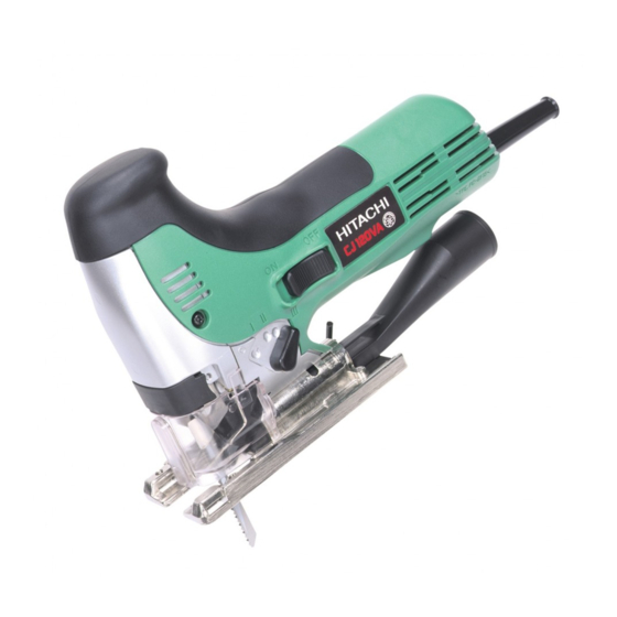
Page 5: Selling Point Descriptions
Fig. 1 (2) High power 740 W motor The Models CJ 120V/VA have the highest power motor in current market (except 110 to 120 V model). And with new orbital system, the Models CJ 120V/VA can make speedy cutting as below. -
Page 6: Specifications
• • • • • • • • • • • • • • • • • • • • • • • • • (silver painted) Type of switch Trigger switch (CJ 120V), snap switch (CJ 120VA) Power input * 740 W (110 to 120 V model: 660 W) - Page 7 Optional Accessories (1) Blades Blade shape Application Blade No. Pitch Code No. Per pkg. No. 1 Wood 321879 (Long) 879336 No. 11 963390 Wood, pulp, synthetic resin 879337 No. 12 963391 879338 No. 15 Steel, pulp, 963392 nonferrous metal, 879339 synthetic resin No.
-
Page 8: Comparisons With Similar Products
(5) Bench stand Type TR 12-B 6. COMPARISONS WITH SIMILAR PRODUCTS Maker HITACHI Model name CJ 120V/VA CJ 110V/VA Wood 120 (4-3/4") 110 (4-1/4") 110 (4-1/4") 135 (5-5/16") 120 (4-3/4") Cutting capacity 10 (3/8") Mild steel 10 (3/8") 10 (3/8") 10 (3/8") -
Page 9: Orbital Mechanism
7-1. Blade Movement In the Models CJ 120V and CJ 120VA, the orbital mechanism moves the blade up-and-down and forward-and- backward in the same manner as the Models CJ 110V and 110 VA. This makes the blade dig well into wood and other soft materials and also discharges cutting chips well to achieve speedy cutting. -
Page 10: Blades
8. BLADES Proper blade selection is very important to obtain the maximum performance of this model. The table below, based on type and thickness of the material to be cut, can be used as a handy reference is selecting the optimum blade. -
Page 11: Precautions In Sales Promotion
9. PRECAUTIONS IN SALES PROMOTION In the interest of promoting the safest and most efficient use of the Models CJ 120V/VA Jig Saw by all of our customers, it is very important that at the time of sale the salesperson carefully ensures that the buyer seriously recognizes the importance of the contents of the Handling Instructions, and fully understands the meaning of the precautions listed on the Caution Plate attached to each tool. -
Page 12: Precautions In Disassembly And Reassembly
The [Bold] numbers in the descriptions below correspond to the item numbers in the Parts Lists and exploded assembly diagram for the Model CJ 120V. And the numbers included in ( ) like as ([99]) means that of the Model CJ 120VA. - Page 13 (3) Disassembly of Housing (A).(B) Set [1] for the Model CJ 120VA (Figs. 6 and 7) • • • • • • • • Remove the Seal Lock Screw (W/Washer) M4 x 10 [20], Tapping Screws (W/Flange) [7] [8], and open one side of the housing.
- Page 14 (4) Disassembly of the Upper Cover [29] ([32]) (Fig. 8) Remove the Lever Bolt [62] ([65]) and Machine Screw (W/Sp. Washer) M4 x 8 [57] ([60]), then Lever [61] ([64]), Lever Spring [60] ([63]), and Fence [56] ([59]) can be separated from the Upper Cover [29] ([32]). Then remove the four Machine Screws M4 x 12 [46] ([49]) (then Guard Bar [28] ([31]) and Packing [38] ([41]) can be separated) and disassemble the Upper Cover [29] ([32]) from the Gear Cover [45] ([48]).
- Page 15 (5) Disassembly of the Plunger [67] ([70]) and the Plunger Holder Ass'y [65] ([68]) (Fig. 9) Remove the two Seal Lock Flat Hd. Screws M5 x 10 [50] ([53]) and then remove the Connector [31] ([34]). Pull out the Pin D6 [63] ([66]) from the Upper Cover [29] ([32]). Pull out the Plunger [67] ([70]) downward from the Upper Cover [29] ([32]).
- Page 16 (6) Disassembly of the Roller Holder [59] ([62]) (Fig. 10) Extract the Needle D5 x 19.8 [58] ([61]) which is press-fitted into the Upper Cover [29] ([32]), and remove the Roller Holder [59] ([62]). Upper Cover [29] ([32]) Roller Holder [59] ([62]) Needle D5 x 19.8 [58] ([61]) Fig.
-
Page 17: Reassembly
(8) Disassembly of the Change Knob [52] ([55]) (Fig. 12) Being very careful not to lose Spring (C) [53] ([56]) and the Steel Ball D3.97 [54] ([57]) inside the Change Knob [52] ([55]), remove the D5 Retaining Ring (E-type) for D5 Shaft [47] ([50]) from the end of the Change Knob [52] ([55]), and remove the Change Knob [52] ([55]) from the Gear Cover [45] ([48]). - Page 18 (3) Carefully ensure that two Washers (A) [39] ([42]), the Orbital Cam [40] ([43]), and the Balance Weights [37] ([40]) are assembled as shown in Fig. 15. (4) During reassembly, be very careful not to forget to install the Felt [44] ([47]) at the lower portion of the Orbital Cam [40] ([43]), as shown in Fig.
-
Page 19: Wiring Diagrams
1.8 0.4 ft-lbs.] • • • Lever Bolt [62] ([65]) 10-3. Wiring Diagrams The wiring is in accordance with Fig. 18 (CJ 120V) and Fig. 19 (CJ 120VA). Switch Controller ass'y Stator coil Noise suppressor Choke coil Armature Choke coil Stator coil Fig. -
Page 20: Insulation Tests
10-4. Insulation Tests On completion of disassembly and repair, measure the insulation resistance and conduct insulation tests (dielectric strength test). Insulation resistance: 7 M Ω or more with 500 V DC Megohm Tester. Dielectric strength: AC 4000 V/1 minute, with no abnormalities 110 V, 230 V, 240 V •... -
Page 21: Standard Repair Time (Unit) Schedules
11. STANDARD REPAIR TIME (UNIT) SCHEDULES Variable 60 min. MODEL Fixed Work Flow CJ 120V CJ 120VA Base Base Locker Housing (A).(B) Armature Ball Bearing (608DDW) Ball Bearing (608DDC2) Stator Carbon Brush Switch Controller Circuit Cord (Model CJ 120VA only) - Page 22 LIST NO. 0593 ELECTRIC TOOL PARTS LIST JIG SAW 2002 • • Model CJ 120V (E1)
- Page 23 PARTS CJ 120V ITEM CODE NO. DESCRIPTION REMARKS USED 321-585 HOUSING (A).(B) SET 321-588 CONTROLLER CIRCUIT 230V-240V 321-589 CONTROLLER CIRCUIT 110V FOR GBR (110V) 321-685 CONTROLLER CIRCUIT 120V FOR USA, CAN 314-887 SWITCH (2P SCREW TYPE) W/LOCK 305-490 TAPPING SCREW (W/FLANGE) D4X30 (BLACK)
- Page 24 PARTS CJ 120V ITEM CODE NO. DESCRIPTION REMARKS USED 305-738 ORBITAL CAM 321-563 GEAR 957-540 WASHER (A) 305-739 ORBITAL PIN 305-740 FELT 321-562 GEAR COVER 949-217 MACHINE SCREW M4X12 (10 PCS.) 673-489 RETAINING RING (E-TYPE) FOR D5 SHAFT 949-423 WASHER M4 (10 PCS.)
-
Page 25: Standard Accessories
STANDARD ACCESSORIES CJ 120V ITEM CODE NO. DESCRIPTION REMARKS USED BLADE NO.41 BLADE NO.123X BLADE NO.42 321-590 TABLE INSERT 321-586 SHUTTER 321-591 DUST COLLECTOR 317-262 CASE OPTIONAL ACCESSORIES ITEM CODE NO. DESCRIPTION REMARKS USED 963-390 JIG SAW BLADES (A) NO. 11 (10 PCS.) 963-392 JIG SAW BLADES (A) NO. - Page 26 LIST NO. 0594 ELECTRIC TOOL PARTS LIST JIG SAW 2002 • • Model CJ 120VA (E1)
- Page 27 CORD (CORD ARMOR D8.8) FOR SUI 500-240Z CORD (CORD ARMOR D8.8) FOR USA, CAN 321-577 SEAL LOCK SCREW (W/WASHER) M4X10 321-595 SLIDE KNOB HITACHI LABEL 608-DDW BALL BEARING 608DDW 360-593U ARMATURE ASS’Y 110V-120V INCLUD. 23, 28 360-593E ARMATURE 230V 360-593F...
- Page 28 PARTS CJ 120VA ITEM CODE NO. DESCRIPTION REMARKS USED 321-565 BALANCE WEIGHT 321-564 PACKING 963-349 WASHER (A) 305-738 ORBITAL CAM 321-563 GEAR 957-540 WASHER (A) 305-739 ORBITAL PIN 305-740 FELT 321-562 GEAR COVER 949-217 MACHINE SCREW M4X12 (10 PCS.) 673-489 RETAINING RING (E-TYPE) FOR D5 SHAFT 949-423 WASHER M4 (10 PCS.)
- Page 29 STANDARD ACCESSORIES CJ 120VA ITEM CODE NO. DESCRIPTION REMARKS USED BLADES NO. 123X BLADES NO. 41 BLADES NO. 42 321-590 TABLE INSERT 321-586 SHUTTER 321-591 DUST COLLECTOR 317-262 CASE OPTIONAL ACCESSORIES ITEM CODE NO. DESCRIPTION REMARKS USED 963-390 JIG SAW BLADES (A) NO. 11 (10 PCS.) 963-392 JIG SAW BLADES (A) NO.
Need help?
Do you have a question about the CJ 120V and is the answer not in the manual?
Questions and answers