Rotax 912 Series Installation Manual
912 series
Hide thumbs
Also See for 912 Series:
- User manual ,
- Maintenance manual (456 pages) ,
- Installation manual (199 pages)

Related Manuals for Rotax 912 Series


Summary of Contents for Rotax 912 Series
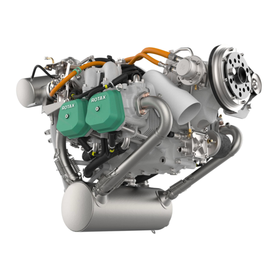
- Page 1 �������� ������� INSTALLATION MANUAL FOR ROTAX® ENGINE TYPE 912 SERIES ROTAX ® 912 ULS 3 WITH OPTIONS part no.: 898642...
- Page 2 Rotax GmbH&Co. KG, Austria, acc, BGBI 1984 no. 448, and shall not, without prior written permission of BRP-Rotax GmbH&Co. KG, be disclosed in whole or in part to third parties. This legend shall be included on any reproduction of these data, in whole or in part.
-
Page 3: Table Of Contents
2) Index ........................7 3) Preface ........................9 3.1) Remarks ........................9 3.2) Engine serial number ....................9 3.3) ROTAX Authorized Distributors for Aircraft Engines ............ 9 4) Safety ........................11 4.1) Repeating symbols ....................11 4.2) Safety information ..................... 11 4.3) Instruction ......................... - Page 4 Drainage piping on airbox and drip trays.............. 92 15.2) Connections for Bowden-cable actuation and limit load..........94 15.3) Requirements on cable actuation ................96 15.4) Requirements on the throttle lever ................97 page 4 Effectivity: 912 Series May 01/2007 Edition 1 / Rev. 0...
- Page 5 21.4) Mechanical rev counter (tach drive): ............... 130 21.5) Monitoring of the intake manifold pressure ............. 131 21.6) Air temperature in the airbox (optional) ..............132 22) Preparations for trial run of engine ..............133 Effectivity: 912 Series page 5 Edition 1 / Rev. 0 May 01/2007...
- Page 6 BRP-Rotax INSTALLATION MANUAL NOTES page 6 Effectivity: 912 Series May 01/2007 Edition 1 / Rev. 0...
-
Page 7: Index
Engine serial number 9 Engine speed 27 Engine suspension 33, 38 Rectifier-regulator 110 Engine views 24 Remarks 9 Exhaust system 39 Rev-counter drive 130 Expansion tank 55 External alternator 116 Effectivity: 912 Series page 7 Edition 1 / Rev. 0 May 01/2007... - Page 8 Temperature in airbox 99 Throttle lever 97 Transport 31 Trial run 133 Vacuum pump 123 Venting line of oil tank 71 Water inlet bend 57 Wiring diagram (electric) 108 page 8 Effectivity: 912 Series May 01/2007 Edition 1 / Rev. 0...
-
Page 9: Preface
In this Manual the installation of all ROTAX 912 Series engines is described. ◆ NOTE: ROTAX 912 Series includes 912 A, 912 F, 912 S, 912 UL, 912 ULS and 912 ULSFR. Before starting with the engine installation, read this Installation Manual carefully. The Manual will provide you with basic information on correct engine installation, a requirement for safe engine operation. - Page 10 BRP-Rotax INSTALLATION MANUAL NOTES Effectivity: 912 Series page 10 Edition 1 / Rev. 0 May 01/2007...
-
Page 11: Safety
The information and components-/system descriptions contained in this Installation Manual are correct at the time of publication. BRP-Rotax, however, maintains a policy of continuous improvement of its products without imposing upon itself any obligation to install them on its products previously manufactured. - Page 12 Due to the varying designs, equipment and types of aircraft, BRP-Rotax makes no warranty or representation on the suitability of its engine’s use on any particular aircraft.
-
Page 13: Instruction
Where differences exist between this Manual and regulations provided by any authority, the more stringent regulation should be applied. This engine may be equipped with an other than the ORIGINAL-ROTAX vacuum pump. The safety warning accompanying the air pump must be given to the owner/operator of the aircraft into which the air pump is installed. -
Page 14: Technical Documentation
They may not represent the actual part in all its details but depict parts of the same or similar function. Therefore deduction of dimensions or other details from illustrations is not permitted. Effectivity: 912 Series page 14 Edition 1 / Rev. 0... - Page 15 All necessary documentation is available from the ROTAX Authorized Distributors or their Service Centers. Installation drawings and a DMU-model for (virtual) installation analysis are available from the ROTAX Authorized Distributors or their Service Centers. Ersatz fuer Ersatz fuer OPTIONAL ALTERNATOR...
- Page 16 BRP-Rotax INSTALLATION MANUAL NOTES Effectivity: 912 Series page 16 Edition 1 / Rev. 0 May 01/2007...
-
Page 17: List Of The Effective
05 01 2007 05 01 2007 05 01 2007 05 01 2007 05 01 2007 05 01 2007 05 01 2007 05 01 2007 05 01 2007 05 01 2007 Effectivity: 912 Series page 17 Edition 1 / Rev. 0 May 01/2007... - Page 18 BRP-Rotax INSTALLATION MANUAL NOTES Effectivity: 912 Series page 18 Edition 1 / Rev. 0 May 01/2007...
-
Page 19: Table Of Amendments
DOA Nr. EASA.21J.048. 00568 chapter page date of remark for date of approval date of signature change approval from authorities inclusion 0 - 25 05 01 2007 DOA* ––––––––––––––––––––––––––––––––––––––––––––––––––––––––––––––––––––––––––––––––––––––––––––––––––––––––––––––––––––––––––––––––––– Effectivity: 912 Series page 19 Edition 1 / Rev. 0 May 01/2007... - Page 20 BRP-Rotax INSTALLATION MANUAL NOTES Effectivity: 912 Series page 20 Edition 1 / Rev. 0 May 01/2007...
-
Page 21: Description Of Design
4 08116 ◆ NOTE: Conversion of the version 2 / 4 to version 3 may be accom- plished by ROTAX Authorized Distributors or their Service Center. 7.2) Standard engine design 4 stroke, 4 cyl. horizontally opposed, spark ignition engine, single central... - Page 22 Components especially developed and tested for this engine are readily available at BRP-Rotax. Following auxiliary equipment has been tested on ROTAX engine type 912 for safety and durability to the standards of aviation. The furnishing of proof in accordance to the latest FAR or EASA has to be conducted by the aircraft manufacturer.
- Page 23 The furnishing of proof in accordance to the latest FAR or EASA has to be conducted by the aircraft manufacturer. exhaust system intake filter Flydat mechanical rev counter electric rev counter shock mount Effectivity: 912 Series page 23 Edition 1 / Rev. 0 May 01/2007...
-
Page 24: Engine Components, Engine Views, Definition Of Main Axes
21 connection for mechanical rev counter 14 electric starter 22 mechanical fuel pump 15 electronic module 23 oil tank 16 compensation tube 24 external alternator 17 connection for manifold pressure 25 exhaust socket page 24 Effectivity: 912 Series Edition 1 / Rev. 0 May 01/2007... - Page 25 BRP-Rotax INSTALLATION MANUAL Fig. 3 00503 cyl. 4 cyl. 3 cyl. 2 cyl. 1 Fig. 5 09147 00504 Fig. 4 Effectivity: 912 Series page 25 Edition 1 / Rev. 0 May 01/2007...
- Page 26 BRP-Rotax INSTALLATION MANUAL NOTES page 26 Effectivity: 912 Series Edition 1 / Rev. 0 May 01/2007...
-
Page 27: Technical Data
7. Cyl. head temperature: see Operators Manual 912 Series, sec. 10.1. 8. Exhaust gas temperature: see section 11.1 9. Range of starting temperature: see Operators Manual 912 Series, sec. 10.1. 10.Ambient temperature for electronic module: see section 19.3 11.Fuel pressure: see Operators Manual 912 Series, sec. 10.1. -
Page 28: Installation Dimensions
Engine dry from serial production with internal alternator, with overload clutch (see section Description of design) ROTAX 912 A, 912 F, 912 UL: Engine weight ..Version 2 and 4: ........57,1 kg (125 lb) Version 3: ..........59,8 kg (132 lb) ROTAX 912 S, 912 ULS: Engine weight .. -
Page 29: Centre Of Gravity Of Engine And Standard Equipment
10 900 11 390 axis y1 - y1 (kg cm²) moment of inertia around 17 400 18 200 09183 axis z1 - z1 (kg cm²) Effectivity: 912 Series page 29 Edition 1 / Rev. 0 May 01/2007... - Page 30 BRP-Rotax INSTALLATION MANUAL NOTES page 30 Effectivity: 912 Series Edition 1 / Rev. 0 May 01/2007...
-
Page 31: Preparations For Engine Installation
Engine preservation The engine is preserved at BRP-Rotax thus warranting proper protection against corrosion for at least 12 month after date of delivery from BRP-Rotax. This warranty is subject to the following conditions: the engine has to be stored in the packing as supplied by BRP-Rotax. -
Page 32: Protective Covering
(if not equipped with an airbox): .. 2x disk plug ▲ WARNING: Protective covering to be utilized for transport and at engine installation only. Before engine operation remove these pro- tections. page 32 Effectivity: 912 Series Edition 1 / Rev. 0 May 01/2007... -
Page 33: Engine Suspension And Position
▲ WARNING: If the engine suspension frame supplied by BRP-Rotax is not used or if modified, certification to the latest requirements such as FAR or EASA has to be conducted by the aircraft manufacturer. -
Page 34: Definition Of Attachment Points
▲ WARNING: The engine suspension to be designed by the aircraft or fuselage manufacturer such that it will carry safely the maxi- mum occurring operational loads without exceeding the max. allowable-forces and moments on the engine attachment points. page 34 Effectivity: 912 Series Edition 1 / Rev. 0 May 01/2007... -
Page 35: Permissible Fitting Positions
6° decline of propeller shaft axis after longer periods of downtime. See FAR, § 33.17. Effectivity: 912 Series page 35 Edition 1 / Rev. 0... - Page 36 The centres of attachment points L1 and R1 must be on an axis y2 parallel to y-axis. 5° Fig. 10 5° 02454 Tolerated roll deviation of parallelism: ......± 5°. (see Fig. 10) page 36 Effectivity: 912 Series Edition 1 / Rev. 0 May 01/2007...
- Page 37 INSTALLATION MANUAL Vertical axis: y-axis must be square to the longitudinal axis of the aircraft. Fig. 11 02455 Tolerated roll deviation of Yaw tolerance: ± 10° (see Fig. 11) Effectivity: 912 Series page 37 Edition 1 / Rev. 0 May 01/2007...
-
Page 38: General Directives For Engine Suspension
BRP-Rotax, especially for the magneto side engine attach- ment to the fireproof bulk head. ▲ WARNING: If the engine suspension frame supplied by BRP-Rotax is not used the engine installation must by ground run tested to the specified loads and for vibration behaviour. Certification to the latest requirements such as FAR or EASA has to be conducted by the aircraft manufacturer. -
Page 39: Exhaust System
▲ WARNING: The exhaust system has to be designed by the aircraft or fuselage manufacturer such, that the limit loads on the points of attachment will not by exceeded. Additional support of exhaust system may be necessary. Effectivity: 912 Series page 39 Edition 1 / Rev. 0 May 01/2007... -
Page 40: Requirements On The Exhaust System
Because of the high temperatures occurring, provide suitable protection against unintentional contact. ■ CAUTION: Secure exhaust system by suitable means according to instal- lation. (1.42 in.) 00776 Fig. 13 page 40 Effectivity: 912 Series Edition 1 / Rev. 0 May 01/2007... -
Page 41: Operating Limits
■ CAUTION: The listed engine performance is given at ISA ((15 °C) (59 °F)) conditions only on engine that is equipped with an unmodified ROTAX tuned exhaust muffler system and air intake box. ~100 mm (3.93 in.) 07131 Fig. -
Page 42: General Directives For Exhaust-System
See Fig. 15. A exhaust system, especially for universal application has been developed by BRP-Rotax. Certification to the latest requirements such as FAR or EASA has to be conducted by the aircraft manufacturer. The following recommendations should help the aircraft manufacturer to plan a suitable exhaust system. -
Page 43: Data For Optional Components Of Exhaust System
8. exhaust elbow assy. (doughnut) See Fig. 16. Material/thickness of the exhaust components: X 15CrNiSi20-12 (1.4828) (AISI 309) a= 1.5 mm (0.059 in.) section A-A 09164 Fig. 16 Effectivity: 912 Series page 43 Edition 1 / Rev. 0 May 01/2007... - Page 44 X 6CrNiTi 189 (1.4541) (stainless) a= 1 mm (0.039 in.) 09159 Fig. 17 exhaust elbow (tailpipe) See Fig. 18. Material/thickness of the exhaust components: X 5CrNi 189 (1.4301) (stainless) a= 1 mm (0.039 in.) 09153 Fig. 18 page 44 Effectivity: 912 Series Edition 1 / Rev. 0 May 01/2007...
- Page 45 X 15CrNiSi 20,12 (DIN 1.4828) (stainless) a= 1 mm (0.039 in.) 09166 Fig. 19 exhaust tube See Fig. 20. Material/thickness of the exhaust components: X 15CrNiSi 20,12 (DIN 1.4828) (stainless) a= 1 mm (0.039 in.) 09167 Fig. 20 Effectivity: 912 Series page 45 Edition 1 / Rev. 0 May 01/2007...
- Page 46 BRP-Rotax INSTALLATION MANUAL NOTES page 46 Effectivity: 912 Series Edition 1 / Rev. 0 May 01/2007...
-
Page 47: Cooling System
12.1) Description of the system See Fig. 21. The cooling system of the ROTAX 912 is designed for liquid cooling of the cylinder heads and ram-air cooling of the cylinders. The cooling system of the cylinder heads is a closed circuit with an expansion tank and overflow bottle. -
Page 48: Operating Limits
But the temperature difference between coolant and cylinder head is not constant and can vary with different engine installation (cowling or free installation, tractor or pusher, flight speed, etc.). Effectivity: 912 Series page 48 Edition 1 / Rev. 0... -
Page 49: Coolant Types
150 °C (300 °F) (for ROTAX 912 UL/A/F) and 135 °C (275 °F) (for ROTAX 912 ULS/ S). It does not require pressure to maintain its boiling point. Due to a lower thermal conductivity the engine temperature will typically run about 5-10 °C (41-... -
Page 50: Check Cooling System - Efficiency Of The Cooling System
During flight test the place with the highest cylinder head temperature must be found, this can vary with different engine installation (cowling or free installation, tractor or pusher, fight speed etc.). Effectivity: 912 Series page 50 Edition 1 / Rev. 0 May 01/2007... - Page 51 If fluid volume is lost and the probe is not fully submerged in the fluid the display could show a lower temperature than actual (measuring air temperature instead of fluid tempera- ture). Effectivity: 912 Series page 51 Edition 1 / Rev. 0 May 01/2007...
-
Page 52: Determination Of Operating Limits, Coolant And Necessary Modification On Radiator Installation
This is possible by calculating the difference between the head material and the coolant temperature. This is done by following the flight test procedure on page 53. Effectivity: 912 Series page 52 Edition 1 / Rev. 0 May 01/2007... - Page 53 ■ CAUTION: In no case a cylinder head temperature higher than the limit of 150 °C (300 °F) (for ROTAX 912 UL/A/F) and 135 °C (275 °F) (for ROTAX 912 ULS/S) can be defined because detonation could not be sufficiently prevented.
-
Page 54: Requirements On The Cooling System
▲ WARNING: The size and layout of the cooling system must be designed to keep the operating temperatures within the specified limits. To minimize flow resistance employ radiator with low flow resistance and parallel flow as realized on the original ROTAX radiator and use short hoses and pipelines. Coolant hoses: temperature durability: min. -
Page 55: Size And Position Of Connections
The aircraft manufacturer has to carry out the check of coolant level in the expansion tank and note it in the daily inspection section of his flight manual according latest issue of Operators Manual ROTAX 912. It is recommended to make adequate precautions for accomplishment of these inspections, e.g. - Page 56 BRP-Rotax INSTALLATION MANUAL 200± 10 mm 252± 5 mm 07136 Fig. 26 Effectivity: 912 Series page 56 Edition 1 / Rev. 0 May 01/2007...
- Page 57 M6x20 and lock washers. Tighten screws to 10 Nm (90 in.lb.). ■ CAUTION: Utilize total slip-on length for hose connection. Secure hoses with suitable spring type clamp or screw clamp. Effectivity: 912 Series page 57 Edition 1 / Rev. 0 May 01/2007...
-
Page 58: Feasible Location Of Radiator
Additionally the system needs an overflow bottle (7) where surplus coolant is collected and returned back into the circuit at the cooling down period. Effectivity: 912 Series page 58 Edition 1 / Rev. 0... - Page 59 Protection by insulation, or routing in a hose with hot air flow or by furnishing the vent line with a bypass opening (slot) (6) before passing through cowling (7). See Fig. 09132 Fig. 30 Effectivity: 912 Series page 59 Edition 1 / Rev. 0 May 01/2007...
- Page 60 Make sure the hose (5) has no kinks. Route it overboard and secure. LOCTITE Ø 6mm (0. 236 in) ® 05294 05295 Fig. 31 Fig. 32 11,5mm (0.453 in) 05033 09126 Fig. 34 Fig. 33 Effectivity: 912 Series page 60 Edition 1 / Rev. 0 May 01/2007...
-
Page 61: General Directives For The Cooling System
INSTALLATION MANUAL 12.9) General directives for the cooling system See Fig. 29. BRP-Rotax offers essential parts of the cooling system for this engine such as radiator, etc.. ▲ WARNING: Certification to the latest requirements to FAR or EASA has to be conducted by the aircraft manufacturer. - Page 62 No provision is made for attachment of the radiator(s) on the engine. ■ CAUTION: Install the radiator without distortion or stressand free of vibrations (rubber mounts are recommended). At installation of a non-original ROTAX radiator take care of sufficient cooling capacity. See section 12.7 Effectivity: 912 Series page 62 Edition 1 / Rev.
-
Page 63: Coolant Capacity
This must also be warranted at "hot day conditions"! Max. permissible cylinder wall temperature on cylinder 2..200 °C (392 °F) (see Fig. 36). Schraube / screw M5 02050 Fig. 36 Effectivity: 912 Series page 63 Edition 1 / Rev. 0 May 01/2007... -
Page 64: 1)General Directives For Ducting Of The Cooling Air
In special cases a separate cold air supply to the air intake filters has to be provided. BRP-Rotax developed especially for this application a non-certified cooling air ducting. ▲ WARNING: Certification to the latest requirements to FAR or EASA has to be conducted by the aircraft manufac- turer. -
Page 65: Data For Optional Components Of Cooling System
15 (0.59 in) (-11.81 in) (-1.18 in) (-0.55 in) engagement (mm) 12.12)Data for optional components of cooling system overflow bottle See Fig. 37. 09148 Fig. 37 Effectivity: 912 Series page 65 Edition 1 / Rev. 0 May 01/2007... - Page 66 See Fig. 39. weight: see section 8. 09165 Fig. 39 ◆ NOTE: The gap between cowling and radiator should be covered by appropriate sealing lips for better efficiency of cooling. Effectivity: 912 Series page 66 Edition 1 / Rev. 0 May 01/2007...
-
Page 67: Lubrication System
13) Lubrication system 13.1) Description of the system See Fig. 40. The ROTAX 912 engine is provided with a dry sump forced lubrication system with a oil pump with integrated pressure regulator. ◆ NOTE: The oil pump is driven by the camshaft. -
Page 68: Limits Of Operation
▲ WARNING: The lubrication system has to be designed such that operating temperatures will not exceed the specified limits. Oil pressure: For oil pressure sensor see Fig. 88/89. see OM 912 Series, section 10.1 Oil temperature: Oil temperature sensor, see Fig. 86/87. see OM 912 Series, section 10.1 ▲... -
Page 69: Checking Of The Lubrication System
◆ NOTE: The required pressure gauges and connection parts are not included in the BRP-Rotax engine delivery. 13.3.1) Measuring of the vacuum Measuring of vacuum in the oil suction line (1) (line from oil tank to oil pump via oil cooler) at a max. distance of 100 mm (4 in) from pump inlet (2). -
Page 70: 2) Measuring Of The Pressure In The Crankcase
This condition is unsafe and must be rectified without delay. max. 0,45 bar (6.53 psi) above at- mospheric pressure Fig. 42 08324 Effectivity: 912 Series page 70 Edition 1 / Rev. 0 May 01/2007... -
Page 71: Requirements On The Oil- And Venting Lines
Protection by insulation, or routing in a hose with hot air flow or by furnishing vent line with a bypass opening (1) before passing through cowling (2). See Fig. 43. Fig. 43 09132 Effectivity: 912 Series page 71 Edition 1 / Rev. 0 May 01/2007... -
Page 72: Connecting Dimensions And Location Of Connections
Oil pump (inlet) (1) ....thread M18 x 1,5 x 11 ◆ NOTE: Suitable for use of a swivel joint. See Fig. 48. Tightening torque of inlet line: .. 25 Nm (18.5 ft.lb) Fig. 44 09123 Effectivity: 912 Series page 72 Edition 1 / Rev. 0 May 01/2007... - Page 73 21 mm (0.83 in.) Fig. 45 00226 Oil pump (inlet) (3) ....thread 3/4-16 UNF (AN-8) Tightening torque of inlet line: .. 25 Nm (18.5 ft.lb) Fig. 46 09123 Effectivity: 912 Series page 73 Edition 1 / Rev. 0 May 01/2007...
- Page 74 Tightening torque of banjo bolt (3) M16x1,5x28: ..35 Nm (25.8 ft.lb) connection with screw connection (2) (optional): thread ........3/4-16 UNF (AN-8) Tightening torque of oil return line: ....25 Nm (18.5 ft.lb) Fig. 47 09175 Effectivity: 912 Series page 74 Edition 1 / Rev. 0 May 01/2007...
-
Page 75: 2) Oil Tank
OUT - oil outlet (7) to oil cooler/oil tank. See Fig. 1x venting nipple (9) outside dia....8 mm (.31 in.) slip-on length ... max. 15 mm (.59 in.) ø165 ø139,2 02469 09124 Fig. 49 Fig. 48 Effectivity: 912 Series page 75 Edition 1 / Rev. 0 May 01/2007... -
Page 76: Feasible Position And Location Of The Oil Tank
Install the oil tank free of vibrations and not directly to the engine. Oil tank cover (3) and oil drain screw (4) to be easily accessible. 09162 Fig. 50 Effectivity: 912 Series page 76 Edition 1 / Rev. 0 May 01/2007... -
Page 77: Feasible Position And Location Of The Oil Cooler
If need be, take appropriate measures like changing size of cooler, partial covering of cooler etc. 13.8) General notes on oil cooler BRP-Rotax offers for this engine an oil cooler (see Illustrated Parts Catalog, latest issue). ▲ WARNING: Certification of this cooler to the latest requirements such as FAR or EASA has to be conducted by the aircraft manufac- turer. -
Page 78: Purging Of Lubrication System
Normally this will take approx. 20 turns. Depending on installation it may take up to 60 turns. ■ CAUTION: Do not use starter for this purpose. Fit propeller and use it to turn engine. Effectivity: 912 Series page 78 Edition 1 / Rev. 0 May 01/2007... -
Page 79: Inspection For Correct Priming Of Hydraulic Valve Tappets
Operators Manual (or SI-27-1997 Oil level check for ROTAX engine type 912 and 914 (Series), current issue). Add oil to engine oil tank to bring the oil level up to the full mark on the dipstick. -
Page 80: Replacement Of Components
(15 psi) direction of rotation of engine appropriate plug 09163 Fig. 51 to oil pump (1) back from engine (2) 05448 max. 0,5 mm (0,02 in.) 05446 Fig. 52 Effectivity: 912 Series page 80 Edition 1 / Rev. 0 May 01/2007... -
Page 81: Data For Optional Components Of Oil System
(6) (straight socket): outside dia ........ 12 mm (0.47 in.) slip-on length ......max. 24 mm (max. 0.94 in) Tightening torque:..... 25 Nm (18.5 ft.lb) Effectivity: 912 Series page 81 Edition 1 / Rev. 0 May 01/2007... - Page 82 BRP-Rotax INSTALLATION MANUAL 04910 Fig. 53 B: LOCTITE 243 Effectivity: 912 Series page 82 Edition 1 / Rev. 0 May 01/2007...
-
Page 83: Fuel System
The fuel system includes the following items: tank coarse filter fine filter / water trap fuel shut off valve electrical fuel pump as well as the required fuel lines and connections Effectivity: 912 Series page 83 Edition 1 / Rev. 0 May 01/2007... - Page 84 Feeding lines to suction side of the mechanical fuel pump (2) lines from pressure side of the mechanical fuel pump to inlet of fuel manifold Returnline from fuel pressure control to fuel tank. Effectivity: 912 Series page 84 Edition 1 / Rev. 0...
-
Page 85: Operating Limits
■ CAUTION: The fuel pressure of an additional auxiliary fuel pump should not exceed 0,3 bar (4.4 psi.) Effectivity: 912 Series page 85 Edition 1 / Rev. 0 May 01/2007... -
Page 86: Requirements Of The Fuel System
If you should encounter problems in this respect during the test period, than the affected components such as the supply line to the fuel pumps have to be cooled. Effectivity: 912 Series page 86 Edition 1 / Rev. 0 May 01/2007... -
Page 87: Connecting Dimensions, Location Of Joints And Directives For Installation
(0,35 mm = 0.014 in.). This is essential for operation of the fuel system as it prevents a loss in fuel pressure. 02772 coordinates [mm] x axis y axis z axis clamp block -385,0 -50,0 ca.110 Effectivity: 912 Series page 87 Edition 1 / Rev. 0 May 01/2007... -
Page 88: 2) Fuel Pressure Control
57. Fuel intake connection (12): fitting (15) ..9/16-18 UNF (AN-6) Tightening torque: 15 Nm (135 in.lb) Fuel outlet connection (13) hose nipple (14) 3/4 DIN 7642 Effectivity: 912 Series page 88 Edition 1 / Rev. 0 May 01/2007... -
Page 89: 3) Check Valve
14.4.3) Check valve Specification: opening pressure ........0,1-0,15 bar (1,5 psi. - 2,2 psi.) permitted pressure in reverse-biasing ..2 bar (29 psi.) burst pressure ........... 5 bar (72,5 psi.) Effectivity: 912 Series page 89 Edition 1 / Rev. 0 May 01/2007... - Page 90 BRP-Rotax INSTALLATION MANUAL NOTES Effectivity: 912 Series page 90 Edition 1 / Rev. 0 May 01/2007...
-
Page 91: Carburetor
The float chamber venting lines (3) lines have to be routed into a ram-air and vacuum free zone or into the airbox, according to the requirements and release of BRP-Rotax. See section 16. These lines must not be routed into the slipstream or down the firewall. -
Page 92: 1) Drainage Piping On Airbox And Drip Trays
BRP-Rotax. See section 16. These lines must not be routed into the slipstream or down the firewall. Pressure differences between intake pressure and pressure in the carburetor chambers may lead to engine malfunction due to incorrect fuel supply. - Page 93 BRP-Rotax INSTALLATION MANUAL Fig. 59 09127 Effectivity: 912 Series page 93 Edition 1 / Rev. 0 May 01/2007...
-
Page 94: Connections For Bowden-Cable Actuation And Limit Load
65 mm (2 ") actuating force: min. 1,5 N (.3 lb) max. 8 N (1,8 lb) limit load: 20 N (4,5 lb) ◆ NOTE: Throttle opens by spring. page 94 Effectivity: 912 Series Edition 1 / Rev. 0 May 01/2007... - Page 95 100 N (22 lb) Directive for choke actuation The choke shaft (3) is marked (4). This mark has to point towards cable engagement (5). Fig. 61 00541 Effectivity: 912 Series page 95 Edition 1 / Rev. 0 May 01/2007...
-
Page 96: Requirements On Cable Actuation
(2) or a cable with pull-push action would have to be used. Secure the bowden cable sleeves (3) in the adjustment screws (4) (e.g. safety wire). page 96 Effectivity: 912 Series Edition 1 / Rev. 0 May 01/2007... -
Page 97: Requirements On The Throttle Lever
These stops have to be designed such to render adjustibility and to prevent overload of the idle stop on the carburetor. The sketch (Fig. 63) depicts a feasible arrangement. Startleistung Take off power Leerlauf Idle Fig. 63 09137 Effectivity: 912 Series page 97 Edition 1 / Rev. 0 May 01/2007... - Page 98 BRP-Rotax INSTALLATION MANUAL NOTES page 98 Effectivity: 912 Series Edition 1 / Rev. 0 May 01/2007...
-
Page 99: Air Intake System
ROTAX tuned exhaust muffler system and air intake box. If it will be necessary to use a different airbox or a modified genuine ROTAX airbox for reasons of installation the certification to the latest requirements such as FAR and EASA has to be conducted by the aircraft manufacturer. -
Page 100: Requirements On The Air Intake System
If an airbox of not ROTAX origin is used provisions for preheating the intake air have to be made to prevent formation of ice in the intake system. -
Page 101: 3) Airbox
With closed or blocked drainage bores fuel could flow into combustion chamber, possibly ruining the engine by hydraulic lock or emerging fuel could drip onto the exhaust system. RISK OF FIRE! . Effectivity: 912 Series page 101 Edition 1 / Rev. 0 May 01/2007... - Page 102 BRP- Rotax. See section 15. These lines must not be routed into the slipstream or down the firewall. Pressure differences between intake pressure and pressure in the carburetor chambers may lead to engine malfunction due to incorrect fuel supply.
- Page 103 Make sure that the air intake tubes of the airbox for fresh air and preheated air are connected correctly (see Fig. 64). ◆ NOTE: Fig. 64 shows the genuine ROTAX airbox. Effectivity: 912 Series page 103 Edition 1 / Rev. 0...
-
Page 104: Data For Optional Components Of Air Intake System
BRP-Rotax INSTALLATION MANUAL 16.3) Data for optional components of air intake system air filter See Fig. 65. weight: see section 8. 09149 Fig. 65 page 104 Effectivity: 912 Series Edition 1 / Rev. 0 May 01/2007... - Page 105 BRP-Rotax INSTALLATION MANUAL airbox See Fig. 66. weight: see section 8. 09174 Fig. 66 Effectivity: 912 Series page 105 Edition 1 / Rev. 0 May 01/2007...
- Page 106 BRP-Rotax INSTALLATION MANUAL NOTES page 106 Effectivity: 912 Series Edition 1 / Rev. 0 May 01/2007...
-
Page 107: Electric System
An excess-voltage protection has to be realized by the aircraft manufacturer in accordance to effective regulations. ▲ WARNING: The certification to the latest requirements such as FAR or EASA has to be conducted by the aircraft manufacturer. Effectivity: 912 Series page 107 Edition 1 / Rev. 0 May 01/2007... -
Page 108: 1) Electromagnetic Compatibility (Emc/Emi)
Items 1-9, 24-25 are included in the standard volume of supply of the engine Items 10-14 are available as accessory Items 15-23 can't be supplied by BRP-Rotax ▲ WARNING: The certification of items/components which are not included in the standard volume of supply of engine has to be conducted by the aircraft manufacturer to the latest requirements such as FAR or EASA. - Page 109 (tachometer) electrical fuel pump 09138 Fig. 67 Effectivity: 912 Series page 109 Edition 1 / Rev. 0 May 01/2007...
-
Page 110: Technical Data And Connection Of The Electric Components
8. ◆ NOTE: The performance specifications are applied to a opti- mal cooling situation. If necessary, use a separate heat sink for the retifier regulator. page 110 Effectivity: 912 Series May 01/2007 Edition 1 / Rev. 0... - Page 111 ■ CAUTION: Never sever connection between terminal C and +B of regulator (e.g. by removal of a fuse) while the engine is running. Overvoltage and regulator damage can occur. Effectivity: 912 Series page 111 Edition 1 / Rev. 0 May 01/2007...
-
Page 112: 3) Electronic Modules
(Fig. 67, pos. (15)) switching voltage: min. 250 V Cyl. 3 Cyl. 4 switching current: min. 0,5 A Wires from the ignition switches connect to the electronic module (see Fig. 71). page 112 Effectivity: 912 Series May 01/2007 Edition 1 / Rev. 0... - Page 113 Check for tight fit. Fig. 72 08323 ◆ NOTE: Faston connector and insulation sheath of the old version are available as spare part. See also SI-912- 013, latest issue. Effectivity: 912 Series page 113 Edition 1 / Rev. 0 May 01/2007...
-
Page 114: 5) Electric Starter
Max. 80 °C (176 °F) temperature range by the electric starter housing. Activate starter for max. 10 sec. (without interruption), followed by a cooling period of 2 min! page 114 Effectivity: 912 Series May 01/2007 Edition 1 / Rev. 0... -
Page 115: 6) Starter Relay
■ CAUTION: Activation of start relay limited to short duration. Over a period of 4 min. operation, the duty cycle is 25%. Fig. 75 09169 Effectivity: 912 Series page 115 Edition 1 / Rev. 0 May 01/2007... -
Page 116: 7) External Alternator (Optional Extra)
(field circuit) (3) and warning lamp circuit (4): via supplied standard plug (Sumitomo 6111-2568) Fig. 76 03199 Cyl. 1 Cyl. 2 Cyl. 3 Cyl. 4 Fig. 77 04902 page 116 Effectivity: 912 Series May 01/2007 Edition 1 / Rev. 0... - Page 117 3 times the prop speed. 1/min. / rpm. n Propeller 1000 1500 2000 2500 rpm. propeller 2000 3000 4000 5000 6000 7000 8000 n Generator rpm. alternator 00547 Fig. 78 Effectivity: 912 Series page 117 Edition 1 / Rev. 0 May 01/2007...
-
Page 118: 8) Connection Of The Electric Rev-Counter (Tachometer)
(in insulation wrap) length approx. 600 mm (24 in) starting from ignition housing. ◆ NOTE: BRP-Rotax developed especially for this application a non-certified electric rev-counter. Certification to the latest requirements such as FAR or EASA has to be conducted by the aircraft manufacturer. See also SI- 13-1996, latest issue. -
Page 119: 9) Battery
BRP-Rotax INSTALLATION MANUAL 17.3.9) Battery See Fig. 67. ■ CAUTION: To warrant reliable engine start use a battery of at least 16 Ah capacity. Effectivity: 912 Series page 119 Edition 1 / Rev. 0 May 01/2007... - Page 120 BRP-Rotax INSTALLATION MANUAL NOTES page 120 Effectivity: 912 Series May 01/2007 Edition 1 / Rev. 0...
-
Page 121: Propeller Drive
2,2727 (50 Teeth/22 T) 2,4286 (51 T/21 T) max. torque: ROTAX 912 UL, A, F for i=2,2727: 238 Nm (176 ft.lb.) (at propeller) ROTAX 912 UL, A, F for i=2,4286: 255 Nm (188 ft.lb.) (at propeller) ROTAX 912 ULS, S for i=2,4286: 315 Nm (232 ft.lb.) (at propeller) - Page 122 If there are no limits found in the technical literature, a max. of 0.1 IPS (inches per second) at 5000 rpm can be assumed. Fig. 80 02581 120 mm (4.72 in.) 09193 page 122 Effectivity: 912 Series May 01/2007 Edition 1 / Rev. 0...
-
Page 123: Vacuum Pump
1,724 or 1,842, i.e. the vacuum pump runs with 0,58 or 0,54 of engine speed. ▲ WARNING: Certification to the latest requirements such as FAR or EASA has to be conducted by the aircraft manufacturer. Fig. 81 08322 Effectivity: 912 Series page 123 Edition 1 / Rev. 0 May 01/2007... - Page 124 BRP-Rotax INSTALLATION MANUAL Fig. 82 08328 page 124 Effectivity: 912 Series May 01/2007 Edition 1 / Rev. 0...
-
Page 125: Hydraulic Governor For Constant Speed Propeller
20.1) Technical data See Fig. 83 ◆ NOTE: See therefore also SB-912-052 "Installation / Use of governors for Rotax engine type 912 and 914", latest issue. drive via prop gear location of the necessary connection on the crankcase: see Fig. 83... - Page 126 BRP-Rotax INSTALLATION MANUAL Fig. 83 08179 page 126 Effectivity: 912 Series May 01/2007 Edition 1 / Rev. 0...
-
Page 127: Connections For Instrumentation
00327 ■ CAUTION: The graph resistance over temperature has been determined, and is effective at the following conditions only. ambient temperature: 20 °C (68 °F) tolerance: ± 10% Effectivity: 912 Series page 127 Edition 1 / Rev. 0 May 01/2007... -
Page 128: Sensor For Oil Temperature
20 °C (68 °F) tolerance: ± 10% BRP-Rotax offers a non-certified temperature indicating instrument. Refer to Illustrated Parts Catalog, latest issue. ▲ WARNING: Certification to the latest requirements such as FAR of EASA has to be conducted by the aircraft manufacturer. -
Page 129: Oil Pressure Sensor
12 V tolerance: ± 5% BRP-Rotax offers a non-certified pressure gauge. Refer to Illustrated Parts Catalog, latest issue. ▲ WARNING: Certification to the latest requirements such as FAR of EASA has to be conducted by the aircraft manufacturer. (Ω) Fig. -
Page 130: Mechanical Rev Counter (Tach Drive)
-465 -160 M18x1, 05483 Fig. 90 Fig. 91 2,6 (0,102 in) 00562 installation dimensions: see Fig. reduction ratio: i = 4 i.e. 1/4 of engine speed page 130 Effectivity: 912 Series May 01/2007 Edition 1 / Rev. 0... -
Page 131: Monitoring Of The Intake Manifold Pressure
■ CAUTION: Flawless operation of the indicating instrument needs the installations of a water trap between engine and instrument for the fuel condensate. Effectivity: 912 Series page 131 Edition 1 / Rev. 0 May 01/2007... -
Page 132: Air Temperature In The Airbox (Optional)
To take air temperature readings in the airbox a connection is provided. This connection is closed on the standard engine by a plug screw. connection: thread M6 thread length approx. 9 mm (3/8") 09172 Fig. 93 page 132 Effectivity: 912 Series May 01/2007 Edition 1 / Rev. 0... -
Page 133: Preparations For Trial Run Of Engine
If nominal performance won't be reached or is in excess of, examination of the installation and engine will be necessary. Consult Maintenance Manual 912. ■ CAUTION: Don't conduct any test flights before fault has been traced and found. Effectivity: 912 Series page 133 Edition 1 / Rev. 0 May 01/2007... - Page 134 BRP-Rotax INSTALLATION MANUAL NOTES page 134 Effectivity: 912 Series May 01/2007 Edition 1 / Rev. 0...
- Page 136 Motornummer / Engine serial no. Flugzeugtype / Type of aircraft Flugzeugkennzeichen / Aircraft registration no. ROTAX® Vertriebspartner ROTAX® authorized distributor www.rotax-aircraft-engines.com ® and TM are trademarks of BRP-Rotax GmbH & Co. KG. © 2006 BRP-Rotax GmbH & Co. KG. All rights reserved.
Need help?
Do you have a question about the 912 Series and is the answer not in the manual?
Questions and answers