Table of Contents
Advertisement
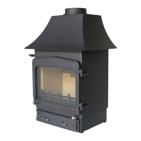
Installation and Operating Instructions for
The Fireview Free Standing Multi Fuel
Range.
Please read this booklet thoroughly before attempting to install or use
this appliance.
Includes Registration and Guarantee Document.
Serial Number
Also detailed on data plate located on the
back of the stove
Please quote when making an enquiry
M____:______
Boiler :______
Canopy:______
A new era in clean, effective multi-fuel stoves.
Woodwarm Stoves
Woodwarm Stoves
Woodwarm Stoves (Est. 1974)
By
Metal Developments Ltd
The Workshop, Wheatcroft Farm, Cullompton, Devon EX15 1RA
Tel : 01884 35806 Fax : 01884 35505
www.woodwarmstoves.co.uk
1
Advertisement
Table of Contents

Related Manuals for Woodwarm Stoves 5.0Kw

Summary of Contents for Woodwarm Stoves 5.0Kw
-
Page 1: Serial Number
M____:______ Boiler :______ Canopy:______ A new era in clean, effective multi-fuel stoves. Woodwarm Stoves Woodwarm Stoves Woodwarm Stoves (Est. 1974) Metal Developments Ltd The Workshop, Wheatcroft Farm, Cullompton, Devon EX15 1RA Tel : 01884 35806 Fax : 01884 35505 www.woodwarmstoves.co.uk... -
Page 2: Table Of Contents
List of Contents General Specifications Page 3 Cautionary Notes on Use Page 4 Regulations and Installation Instructions Page 4 Hearth Page 4 Stove Site and Minimum Clearances Page 5 Chimney and Flue Page 5 Air Ventilation and Free Air Page 5 Flue Appliance Outlet Positions Page 6 Flue Outlet Configuration... -
Page 3: General Specifications
Class 1: BS EN 13240:2001 + Amd 2:2004. For Intermittent use only. Unsuitable for use in a shared flue system. Use only recommended fuels. Table 1 Air Inlet grills must be so positioned that they are not liable to blockage. 5.0Kw 6.0Kw 7.0Kw 9.0Kw 10Kw 12.0Kw 12.0Kw... -
Page 4: Cautionary Notes On Use
Cautionary Notes on Use De-Ashing To ensure that the stove will not over fire whilst the ashpit door is open, we would strongly recommend that de-ashing is only undertaken when the fuel load is almost exhausted, the stove is out or in a very low state. Furthermore, once the riddling has been complete it is essential to fully open the main fire door prior to opening the ashpit door. -
Page 5: Stove Site And Minimum Clearances
non-combustible material. The positioning of the stove and the size of the hearth is governed by Building Regulations for Class 1 Appliances. These regulations state that the hearth must extend at least 225mm in front and 152mm to the side of the stove. This can be covered with decorative tiles so long as these are also non-combustible. -
Page 6: Flue Appliance Outlet Positions
Flue Appliance Outlet Positions Diagram 1 Point where flue passes through Clearances to flue outlet weather surface (Notes 1,2) at or within 600mm at least 600mm of the ridge. above the ridge. Datum for horizontal elsewhere on a roof at least 2300mm horizontally from measurements (weather pitched or flat) the nearest point on the weather... -
Page 7: Flue Outlet Configuration
Flue Outlet Configuration Rain Cap Diagram 2 Flue Vent Flexible Liner Tee With Removable Cap Register Plate Woodwarm Rear Flue Adaptor... -
Page 8: Installing The Stove
INSTALLING THE STOVE Remember to leave sufficient clearance in front of the stove for the hinged ashpit door to open fully. Place stove on chosen level hearth and remove any packaging materials. The shrink polythene can be used as a cover for the stove whilst installation is in progress as fire cement will mark the stove paint surface if left. -
Page 9: Baffle
Replace the canopy if removed and check the base to ensure that the rope which makes the seal between the canopy and the body of the stove is in place (if needed it can be held in place with a smear of fire cement). The flue spigot supplied with the Woodwarm is either 152mm or 178mm depending on your model. -
Page 10: Fire Doors
FIRE DOORS FOR ALL MODELS Check when refitting the fire door that the rope seal on the inner face of the door is making an even contact with the stove body when the door is closed. Your New Fireview Stove has a new style door catch to make it easier and safer to use your stove. -
Page 11: Operation Of The Grate
Diagram 7 OPERATION OF GRATE Your stove is fitted with a multi-fuel grate (diagram 8 & 8A) which will enable you to burn wood or solid fuel equally effectively. It consists of a grate lever operating handle (shown in yellow), grate bars (shown in blue) and the grate link bar (shown in red). -
Page 12: Commissioning
COMMISSIONING On completion of the installation and after allowing a suitable period of time for any fire cement or mortar joints to dry out, the stove should be cleaned using a soft dry cloth. Check joints and seals, especially boiler connections. Ensure that any boiler connections are the right way round. -
Page 13: Daily Routine, Maintenance And Servicing
DAILY ROUTINE , MAINTENANCE AND SERVICING When properly used a Woodwarm Fireview stove is absolutely safe. There is an operating tool provided to operate all the various controls. Do not leave the operating tool attached to the stove when the stove is in use as it will get very hot. Obviously when the stove is in use the body will be too hot to touch by hand. -
Page 14: To Achieve Cleanburn
Diagram 9 Close Air Bleed Hole Open Open Close TO ACHIEVE CLEAN BURN This section applies for the burning of dry wood and to broad based long flame path solid fuels. Take some time to familiarise yourself with the air controls of the stove (diagram 9) to achieve the clean burn state that these stoves are renowned for. -
Page 15: Overnight Burning
Air Bleed Control A small air bleed hole adjustment is provided, it is either located on the airwash lever, or behind it. Its function is to allow you to “Set” the stove to the chimney draught. Open it fully and over the first couple of extended burning peri- ods, monitor the result of your stove's slumber. -
Page 16: Ordering And Installation Of Retrofit Boilers
ORDERING and INSTALLATION OF RETROFIT BOILERS All the models have a variety of boilers that can be retro-fitted and have pre-drilled holes in the body and these are covered with blanking plates which can be knocked out using a hammer (do ensure you have the right holes by offering the boiler up to the holes prior to removing them) and when ordering boilers for retro-fit please state your stove model as some need a change of baffle. -
Page 17: Removing Boilers
If time clock and/or room thermostats are to are fitted Limit then remove the link between A & B and replace it with the device. NB. Time clocks and room thermostats are only appropriate for Woodwarm Stoves which have an Aquastat Control fitted. Pump Connections Limit... -
Page 18: Typical 2 Pipe Central Heating Circuit
Typical 2 Pipe Central Heating Circuit in Conjunc Vent Pipes 22mm Expansion Tank Mains Water Gravity Circuit Should be 30% of the Total Boiler Load 28mm Cold Fill Dead Loop 28mm High Pipe Stat 28mm (Injection Tee 28mm) Direction of Flow 28mm to 15mm Reducer Circulation Pump... - Page 19 ction with Split Saddle Boilers (Indirect Cylinder) Diagram 12 Cold Water Tank Hot Water For Taps...
-
Page 20: Typical 4 Pipe Central Heating Circuit
Typical 4 Pipe Central Heating Circuit in Conjunc Vent Pipes 22mm Expansion Tank Mains Water Gravity Circuit Should be 30% of the Total Boiler Load 28mm Cold Fill Dead Loop 28mm High Pipe Stat Low Pipe Stat Drain Point Circulation Pump... - Page 21 ction with Split Saddle Boilers (Indirect Cylinder) Diagram 13 Cold Water Tank Hot Water For Taps...
-
Page 22: Roof Boilers
ROOF BOILERS - ONLY available in conjunction with the split saddle boilers Roof boilers are constructed with or without a top flue outlet and this must be specified, along with the stove model when ordering. They have two 1" Male BSP stubs. They are used only in conjunction with the split saddle boilers for your stove model, to increase the boiler output and reduce room output. -
Page 23: Aquastat Calibration
AQUASTAT CALIBRATION Only applicable for the FIREVIEW 20KW fitted with the 53000Btu split saddle boiler This stove has an Aquastat fitted as standard (diagram 15), and in conjunction with High and Low pipe thermostats assists the stove to maintain the boiler temperature by automatically allowing either more or less air into the fire chamber via the airwash depending on the Control Knob setting. -
Page 24: Fault Finding
FAULT FINDING A) Stove smokes on lighting or when fire door is opened Flue ways blocked - sweep chimney and flue. Baffle incorrectly fitted. Adverse wind conditions, or down draught - check height and diameter of chimney. Flue not connected (or not sealed) to appliance or chimney . B) Fire fails to burn overnight - fuel burnt through Insufficient dry fuel. -
Page 25: Fireview Double Stoves Additional Installation And Operating Instructions
FIREVIEW DOUBLE STOVES ADDITIONAL INSTALLATION AND OPERATING INSTRUCTIONS HEARTH The stove must stand on a fireproof hearth which must be at least 127mm thick and constructed of a non-combustible material. The positioning of the stove and the size of the hearth is governed by Building Regulations for Class 1 Appliances. -
Page 26: The Woodwarm Guarantee
THE WOODWARM STOVES GUARANTEE Metal Developments Ltd offer a five year guarantee which covers the main structure of the stove including the construction and quality of workmanship. In the unlikely event of any failure we will replace any defective part free of charge, labour cost excluded. -
Page 27: Details Of Product Registration
DETAILS OF PRODUCT REGISTRATION FOR OWNER RETENTION MODEL NUMBER AND SERIAL NUMBER OF STOVE M --- (Found on the data plate located on the pull-out plate on right hand underside of stove also on the front of this booklet) Date of Purchase .. - Page 28 Useful Contacts HETAS PO Box 37 Bishops Cleeve Gloucestershire GL52 9TB www.HETAS.co.uk Solid Fuel Association The Old School House Church Street Sutton In Ashfield Nottinghamshire NG17 1AE Tel: 0800 600000 Guild of Master Sweeps Tel: 01953 451322 www.guild-of-master-sweeps.co.uk The National Association of Chimney Sweeps Unit 15 Emerald Way Stone Business Park...
Need help?
Do you have a question about the 5.0Kw and is the answer not in the manual?
Questions and answers