
Related Manuals for Hammerhead Dune Buggy GT250


Summary of Contents for Hammerhead Dune Buggy GT250
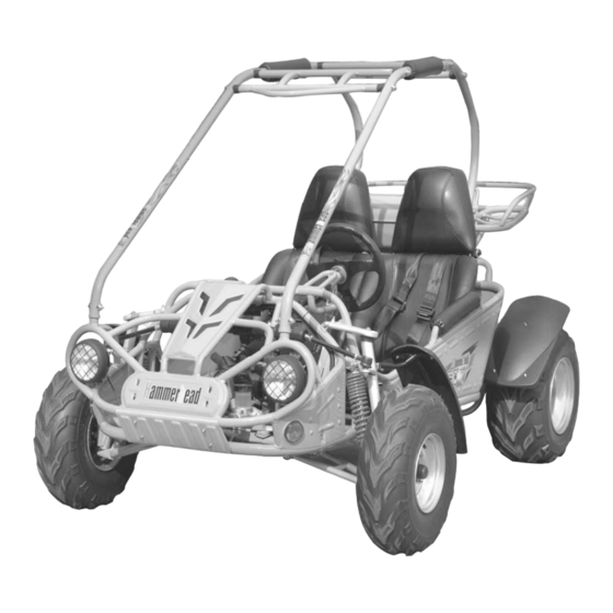
- Page 1 Owner's Manual READ THIS MANUAL CAREFULLY, IT CONTAINS IMPORTANT SAFETY INFORMATION. Dune Buggy...
- Page 2 No dealer is authorized to modify this Emission Control System Warranty. If you have any questions regarding your warranty rights and responsibilities, you should contact Hammerhead Off-Road, Inc.
- Page 3 CONTENTS OWNER' S MANUAL Page...
- Page 4 FOREWORD Thank you for purchasing our dune buggy. We hope you will enjoy it. Before it B f you start to operate the Dune Buggy, please read through this Owner's Manual carefully as it contains important safety and maintenance information. Failure to follow the warnings contained in this manual can result in serious injuries or death.
-
Page 5: A Few Words About Safety
A FEW WORDS ABOUT SAFETY In order to keep everyone safe, you must take responsibility for the safe operation of your Dune Buggy. To help you make informed decisions about safety, we have provided operating procedures and other information on labels and in this manual. This information alerts you to potential hazards that could hurt you or others. -
Page 6: Important Safety Information
IMPORTANT SAFETY INFORMATION Your Dune Buggy will provide you with many years of service and pleasure.Providing you take responsibility for your own safety and understand the challenges you can meet while driving. There is much that you can do to protect yourself while operating your dune buggy. You'll find many helpful recommendations throughout this manual. - Page 7 IMPORTANT SAFETY INFORMATION Drive within Your Limits Pushing limits is another major cause of Dune Buggy accidents. Never drive beyond your personal abilities or faster than conditions warrant. Remember that alcohol, drugs, fatigue, and ina ention can significantly reduce your ability to make good judgments and drive safely.
-
Page 8: Safety Labels
SAFETY LABELS This section presents some of the most important information and recommendations to help you drive your Dune Buggy safely. Please take a few moments to read these pages. The labels should be considered permanent parts of the Dune Buggy. If a label comes o or becomes hard to read, contact your dealer for warning label replacements. -
Page 9: Are You Ready To Drive
ARE YOU READY TO DRIVE ? Before each drive, you need to make sure that you and your dune buggy are both ready to drive. To help get you prepared, this section discusses how to evaluate your driving readiness, what items you should check on your dune buggy, and adjustments to make for your comfort, convenience, or safety. - Page 10 ARE YOU READY TO DRIVE ? ARE YOU READY TO DRIVE ? Additional Driving Gear Additional Driving Gear In addition to a helmet and eye protection, we also recommend: Sturdy o -road motorcycle boots to help protect your feet, ankles, and lower legs. O -road motorcycle gloves to help protect your hands.
-
Page 11: Safe Driving Precautions
SAFE DRIVING PRECAUTIONS O -Road Use Only Your dune buggy and its tires are designed and manufactured for o -road use only, not for use on pavedsurfaces. Driving on paved surfaces can a ect the dune buggy handling and control. You should not drive your dune buggy on paved surfaces. - Page 12 SAFE DRIVING PRECAUTIONS Use Dune Buggy on Unfamiliar or Rough Terrain Before driving in a new area, always check the terrain thoroughly. Don't drive fast on unfamiliar terrain or when visibility is limited (it's sometimes di cult to see obstructions like hidden rocks, bumps, or holes in time to react).
- Page 13 94.46in.(2450mm) 56.18in.(1427mm) 59.35in.(1512mm) 73.42in.(1865mm) 45.7in.(1160mm) 39.4in.(1000mm) 6.7in.(170mm) 250cc 72mm X 60mm Vacuum diaphragm C.D.I. 30 OZ 12V 10Ah...
- Page 14 <7m@20miles/h 73miles/h(or limited as customers require) Hydraulic disc, left foot control Independent Dual Swing Arm/Double Oil damped Shock Chain...
-
Page 17: Component Locations
OPERATION Component locations Figure 2 Figure 3... -
Page 18: Seat Adjustment
OPERATION C. Passengers The dune buggy allows for two riders only. Combine maximum weight of driver and the passenger should not exceed 180kg or 400lbs. D. Seat Adjustment The seat must always be securely fastened in the position which best affords the operator control of the foot pedals, steering wheel, and the remote a. -
Page 19: Service Instructions
OPERATION/SERVICE INSTRUCTIONS F. Starting And Operating Instructions • • Figure 5 SERVICE INSTRUCTIONS A. Service Air Cleaner Service air cleaner every 20 hours Figure 6... -
Page 20: Engine Lubrication
SERVICE INSTRUCTIONS B. Engine Lubrication WARNING Used Oil Must Be disposed of at a proper collection Center Figure 7 C. Spark Plug Figure 8 D. Carburetor Adjustment... -
Page 21: Cleaning Instructions
SERVICE INSTRUCTIONS a. Warm up the engine (5~10min) b. Tighten the air screw gently. Backout 2-3/8 turns counter clockwise. (1400RPM). adjusting as the RPM reaches the top speed. SCREW B THROTTLE SCREW A Figure 9 E. Cleaning Instructions F. Dune Buggy Lubrication G. -
Page 22: Chain Adjustment
SERVICE INSTRUCTIONS H. Chain Adjustment I. Adjustment of Front And Rear Shock LEFT ROTATE RIGHT ROTATE J. Storage Instruction SPRING ADJUSTMENT CAM Figure 11 WARNING WARNING Do not drain fuel while engine is hot. Be sure to move outside before draining fuel. -
Page 23: Front Wheel Replacement
REPAIR A. Front Wheel Replacement Do not disassemble the castle nuts when you replace the front wheels. It is only necessary to remove the 4 lug nuts to remove the wheel. (See Fig. 12) Figure 12 B. Rear Wheel Replacement Do not disassemble the castle nuts when you replace the rear wheels and hub assembly. -
Page 24: Front Wheel Alignment
REPAIR C. Front Wheel Alignment LOOK NUT, FR. WHEEL TIE ROD LEFT ROATE RIGHT ROATE RIGHT ROATE LEFT ROATE FR. WHEEL TIE ROD Figure 14... -
Page 25: Periodical Check And Services
Replace gearbox oil Chassis Fuel switch/fuel tank Battery Valve clearance of engine A: adjust C: clean I: inspect, clean or replace if necessary. L: lubricate R: replace WIRING DIAGRAM STARTING GT250 RELAY R/ W IGNITION HEADLIGHT SWITCH CHOKE BRAKE ASSY.
Need help?
Do you have a question about the Dune Buggy GT250 and is the answer not in the manual?
Questions and answers