Table of Contents
Advertisement
Quick Links
Advertisement
Table of Contents

Related Manuals for Balboa Instruments Poolux


Summary of Contents for Balboa Instruments Poolux
- Page 1 Installation and Configuration Manual...
-
Page 2: Important Notices
Important Notices SAFETY PRECAUTIONS FCC STATEMENT The Warnings, Cautions, and Notes contained in this This equipment has been tested and complies with the manual have the following significance. limits for a Class B digital device, pursuant to Part 15 of the FCC rules. -
Page 3: Important Water Safety Instructions
Important Water Safety Instructions When installing and using this Control System, basic safety precautions should always be followed, including those listed below: READ & FOLLOW ALL INSTRUCTIONS The effects of hyperthermia include: DANGER - To reduce the risk of drowning from hair Unawareness of impending hazard. -
Page 4: Important Electrical Safety Instructions
Important Electrical Safety Instructions When installing and using this Control System, basic safety precautions should always be followed, including those listed below: READ & FOLLOW ALL INSTRUCTIONS GFCI circuit breaker, switch or other device capable DANGER - Risk of electric shock. Before of opening all ungrounded conductors in the supply making any electrical connections, make certain that circuit. -
Page 5: Table Of Contents
Poolux System Overview ........ - Page 6 Table of Contents Connecting High Voltage Components To The System Control Center ..... . 28 General Requirements For High Voltage Equipment Wiring ......28 Pumps .
- Page 7 Poolux Wireless Panel Cradle Installation Option ....... . . 68...
-
Page 8: Diagrams
Fig. 1 Poolux System Overview ........ - Page 9 Diagrams Fig. 33 “S1” Switch and DIP Switches ........47 Fig.
-
Page 10: Poolux System Overview
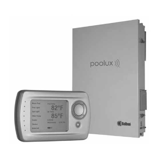
Pool Dolphin™II Wireless Floating Remote Fig. 1 Poolux System Overview CAUTION: THE EQUIPMENT AND CONTROLS SHALL BE LOCATED NOT LESS THAN 3 METERS HORIZONTALLY FROM THE POOL/SPA. ATTENTION: MAINTENIR UNE DISTANCE MINIMALE, M ESUREE DANS UN PLAN HORIZONTAL, DE 3 M ENTRE... -
Page 11: Poolux Specifications
Poolux Specifications ELECTRICAL Power Requirements 120/240VAC, 50/60 HZ, 80 AMPS MAX Outputs 6 - Motorized Valve Actuators 24 VAC, 0.75A max 8 - 30 AMP Relays 2 - Dimmable Light Circuits - 120 VAC, 8.3A max (1000W) each, GFCI protected 1 - Fill Valve 24 VAC, 0.5A max (in place of valve actuator #6) -
Page 12: Package Content
WHAT IS INCLUDED: WHAT IS NOT INCLUDED: System Control Center (P/N# 53691) Circuit Breakers w/ECOmatic (P/N# 54210) None are included with the Poolux. Wireless Panel (P/N# 53963) See inside of door for suitable breakers. w/charging base and wall adapter Wire Wireless Transceiver... -
Page 13: Plumbing Schematic Suggestions
Plumbing Schematic Suggestions NOTE: pH/ORP and Chlorine Generator board shown is optional POOL/SPA SYSTEM CONDUCTIVITY SENSOR LOCATION COM PORTS POC MODULES POOL MON/ WIRELESS EXPANSION BOX COM B TECH PANEL TRANSCEIVER 24VAC IN COM A COM C TEMP SENSORS TEMP CHEMICAL SENSORS WATER... -
Page 14: Pool/Spa System With Pump Operated Pool Cleaner
Plumbing Schematic Suggestions (cont’d) NOTE: pH/ORP and Chlorine Generator board shown is optional POOL/SPA SYSTEM WITH PUMP OPERATED POOL CLEANER CONDUCTIVITY SENSOR LOCATION COM PORTS POC MODULES POOL MON/ WIRELESS EXPANSION BOX COM B TECH PANEL TRANSCEIVER 24VAC IN COM A COM C TEMP SENSORS... -
Page 15: Pool/Spa System With Pressure Cleaner, Solar, Jet Pump, Blower & Water Feature
NOTE: pH/ORP and Chlorine Generator board shown is optional POOL/SPA SYSTEM WITH PRESSURE CLEANER, SOLAR, JET PUMP, BLOWER & WATER FEATURE CONDUCTIVITY SENSOR LOCATION COM PORTS WIRELESS POC MODULES POOL MON/ EXPANSION BOX COM B TECH PANEL TRANSCEIVER 24VAC IN COM A COM C TEMP... -
Page 16: Pool/Spa System With Valve-Controlled Cleaner
Plumbing Schematic Suggestions (cont’d) NOTE: pH/ORP and Chlorine Generator board shown is optional POOL/SPA SYSTEM WITH VALVE-CONTROLLED CLEANER CONDUCTIVITY SENSOR LOCATION COM PORTS POC MODULES POOL MON/ WIRELESS EXPANSION BOX COM B TECH PANEL TRANSCEIVER 24VAC IN COM A COM C TEMP SENSORS TEMP... -
Page 17: Pool/Spa System With Pressure Cleaner (Valved), Jet Pump, Blower & Water Feature
NOTE: pH/ORP and Chlorine Generator board shown is optional POOL/SPA SYSTEM WITH PRESSURE CLEANER (VALVED), JET PUMP, BLOWER & WATER FEATURE CONDUCTIVITY SENSOR LOCATION COM PORTS POC MODULES POOL MON/ WIRELESS EXPANSION BOX COM B TECH PANEL TRANSCEIVER 24VAC IN COM A COM C TEMP... -
Page 18: Pool/Spa System With Solar
Plumbing Schematic Suggestions (cont’d) NOTE: pH/ORP and Chlorine Generator board shown is optional POOL/SPA SYSTEM WITH SOLAR CONDUCTIVITY SENSOR LOCATION COM PORTS POC MODULES POOL MON/ WIRELESS EXPANSION BOX COM B TECH PANEL TRANSCEIVER 24VAC IN COM A COM C TEMP SENSORS TEMP... -
Page 19: Pool Only System Or Spa Only System (No Booster)
NOTE: pH/ORP and Chlorine Generator board shown is optional POOL ONLY SYSTEM OR SPA ONLY SYSTEM (NO BOOSTER) CONDUCTIVITY SENSOR LOCATION COM PORTS POC MODULES POOL MON/ WIRELESS EXPANSION BOX COM B TECH PANEL TRANSCEIVER 24VAC IN COM A COM C TEMP SENSORS TEMP... -
Page 20: Pool Only System With Solar, Cleaner Pump And Water Feature Pump
Plumbing Schematic Suggestions (cont’d) NOTE: pH/ORP and Chlorine Generator board shown is optional POOL ONLY SYSTEM WITH SOLAR, CLEANER PUMP AND WATER FEATURE PUMP CONDUCTIVITY SENSOR LOCATION COM PORTS WIRELESS POC MODULES POOL MON/ EXPANSION BOX COM B TECH PANEL TRANSCEIVER 24VAC IN COM A... -
Page 21: Pool Only System With Valve-Operated Cleaner & Pump-Driven Water Feature
NOTE: pH/ORP and Chlorine Generator board shown is optional POOL ONLY SYSTEM WITH VALVE-OPERATED CLEANER & PUMP-DRIVEN WATER FEATURE CONDUCTIVITY SENSOR LOCATION COM PORTS POC MODULES POOL MON/ WIRELESS EXPANSION BOX COM B TECH PANEL TRANSCEIVER 24VAC IN COM A COM C TEMP SENSORS... -
Page 22: Spa Only System With Jet Pump, Spa Blower & Pump-Driven Water Feature
Plumbing Schematic Suggestions (cont’d) NOTE: pH/ORP and Chlorine Generator board shown is optional SPA ONLY SYSTEM WITH JET PUMP, SPA BLOWER & PUMP-DRIVEN WATER FEATURE CONDUCTIVITY SENSOR LOCATION COM PORTS POC MODULES POOL MON/ WIRELESS EXPANSION BOX COM B TECH PANEL TRANSCEIVER 24VAC IN COM A... -
Page 23: Mounting The System Control Center
Mounting the System Control Center IMPORTANT: ATTENTION: BE SURE THE LOCATION CHOSEN FOR THE PLEASE READ THE FOLLOWING MOUNTING CON- SYSTEM CONTROL CENTER ALLOWS UNOBSTRUCTED SIDERATIONS BEFORE INSTALLING THE SYSTEM ACCESS TO THE GFCI PROTECTING THE UNDERWATER CONTROL CENTER LIGHT CIRCUIT. THE GFCI IS LOCATED ON THE RIGHT SIDE OF THE BOX. -
Page 24: The Poolux Control System
The System enclosure includes a number of features that are often considered optional like dimmable incandescent lighting. Other features like the fill valve are unique. The integration of the optional chlorine generation capablility rounds out the super-capable Poolux controller from Balboa. INSIDE THE SYSTEM ENCLOSURE... -
Page 25: Main Controller Circuit Board
MAIN CONTROLLER CIRCUIT BOARD COM B TB7 COM C TB8 COM A TB6 Pool Monitor/Technician Panel J32 Expansion Controller COM TB5 Wireless Transceiver J5 Conductivity Sensor COM PORTS WIRELESS POC MODULES POOL MON/ EXPANSION BOX COM B TECH PANEL TRANSCEIVER 24VAC IN Chemical 24VAC IN TB4... -
Page 26: System Control Center Wiring
Control Center. used to complete the electrical installation of the Balboa Poolux must be in accordance with the National Electrical Run the conduit from the Power Supply Panel of the house Code or the Canadian Electric Code, as well as any local to the System Control Center. -
Page 27: Circuit Breaker Installation
CIRCUIT BREAKER INSTALLATION CONTROL ELECTRONICS POWER CONNECTION The circuit breaker sub-panel has space for up to 8 single The System Control Center requires 120VAC power to operate position or 4 double position circuit breakers. The installer the control electronics and the chlorine generator. Wire the is responsible for providing circuit breakers of appropriate 2-position terminal block to an installer supplied 120VAC ratings. -
Page 28: Connecting High Voltage Components To The System Control Center
Connecting High Voltage Components to the System Control Center GENERAL REQUIREMENTS FOR HIGH VOLTAGE EQUIPMENT WIRING Check to see that all equipment motors have 240V-rated Equipment: Wire the line power to the two built-in thermal protection before installing. line terminals of the relay and the equipment to the two adjacent load terminals. -
Page 29: Pumps
1000W of 120VAC lighting. Two-speed Pumps Bring the wires from the lights into the high voltage The Balboa Poolux Control Center is capable of being compartment. Connect the ground wire from the lights to configured to control one or more two-speed pumps. Two the grounding bar near the GFCI. -
Page 30: Connecting Low Voltage Components To The System Control Center
RELAY 7 RELAY 8 and through the cable entry slot provided on the bottom left of the Poolux Control Center. 2. Continue the cable through the low voltage compartment and over the top of the low voltage Fig. 20 Fill Valve, TB12 Location on System compartment partition. -
Page 31: Fireman's Switch Connection For Heater
Connecting Low Voltage Components to the System Control Center (cont’d) After all low voltage wiring has been installed, arrange the wiring so that it is somewhat evenly spaced along the length of the entry slot. Secure the wires by tightening the two screws. FIREMAN’S SWITCH CONNECTION FOR HEATER LOW VOLTAGE CONTROL CIRCUIT FOR HEATERS IN3+... -
Page 32: Temperature Sensors
Temperature Sensors The Pool System uses high quality 30K ohm thermistor type temperature sensors. Two sensors are provided (one for Air and one for Water). If this control is used with a solar heating system, an optional solar sensor must be purchased separately. -
Page 33: Air Temperature Sensor Installation (In The Sytem Enclosure)
WARNING: DO NOT USE 10K OHM SENSORS OR OTHER MANUFACTURER’S SENSORS WITH THIS CONTROL. INCORRECT TEMPERATURE READINGS WILL RESULT. AIR TEMPERATURE SENSOR INSTALLATION (IN THE SYTEM ENCLOSURE) 1. If the System Control is not installed in a building and is otherwise not influenced by direct sunlight, the temperature sensor can be mounted to the bottom of the enclosure. -
Page 34: Locating And Installing The Spa-Side Control Panel
Locating and Installing the Spa-Side Control Panel LOCATION GUIDELINES: The Spa-side Control Panel is hereafter referred to as the “Panel", and should be carefully planned and installed during the initial pool/spa construction. This will allow for important steps to be completed before the concrete or gunite is placed. -
Page 35: Installations Through A Vertical Wall
INSTALLATIONS THROUGH A VERTICAL WALL 3. Provide a 1" conduit. 4. Complete the Installation of the Conduit Provide a 1" conduit through the concrete/gunite at the A. Before additional concrete is placed over the location selected for the Panel. The Panel will extend route of the conduit to the System Control Center, into the inside diameter of the conduit and the cable complete the installation of the conduit. -
Page 36: Fig. 27 Mounting The Spa-Side Control Panel
Locating and Installing the Spa-Side Control Center (cont’d) 5. Cut the excess 1" conduit flush with the final 8. Mount the panel. finished surface. Dry fit the Panel against the mounting surface to be sure there are no high points that need to be removed. After all finish work has been completed (plaster, tile, Clean the mating surfaces and then apply a bead coping stone, deck finished, etc.), cut the 1"... -
Page 37: Installing Spa-Side And Optional Dolphin Base Transceiver Modules
2. Run the cable back to the low-voltage compartment of (performance). (For Dolphin Use: Clear line of sight the Poolux Control Center and plug the connector into between the receiver and the pool/spa provides the the 6-pin connector J31 labeled DOLPHIN RF. -
Page 38: Ph/Orp/Conductivity
Care should be taken when unpacking and board (PN 22857) and position it over the connector handling all electrodes. J11, located in the upper left corner of the Poolux Preparations for use Board (P/N 22890). After ensuring proper alignment... - Page 39 3. Millivolt reading should be between 500-750 mV. (Note: The platinum or gold sensing tip of an ORP electrode should The Poolux display does not display mV.) be cleaned just like a pH electrode. The surface can also be cleaned with an abrasive as a last resort. Gently scour the 4.
-
Page 40: Optional Chlorine Generation Cell Installation
Optional Chlorine Generation Cell Installation In conjunction with the chemical sensors, the chlorine generator cell can help minimize the management and use of liquid or solid chlorine products. INSTALLATION OF THE ELECTROLYTIC CELL THE CHLORINE GENERATOR OPTION CONTAINS: Other considerations regarding cell locations Factory-installed control electronics with display When correctly installed, the Cell will produce (installed in the System Control Center) -
Page 41: Fig. 29 Chlorine Generator Cell Location In Plumbing
Connecting the cell cord to the cell Water Flow 1. Reinstall the cell back into the cell housing. In most cases (for 1.5” and 2” PVC) the total water flow can be directed through the Cell Housing as shown in Sketch 2. -
Page 42: Expansion Controller Connection
Expansion Controller Connection This section only includes instructions on connecting the Expansion Controller(s) to the System Control Center. A single installation may utilize up to four expansion boxes. INSTALLATION OF AN EXPANSION BOX 1. Install the Expansion Controller following the installation instructions that are included with it. -
Page 43: Dip Switch Settings
DIP Switch Settings BEFORE Powering Up the System IDENTIFY THE DEFAULT CONFIGURATION THAT MOST CLOSELY MATCHES THE PLUMBING AND EQUIPMENT INSTALLED. DIP SWITCH SETTINGS Set The Dip Switch Settings On The Circuit Board As Shown. When looking at the DIP switches on the Service Panel, the ON position is to the right. 1. -
Page 44: Start Up: Configuration Parameters
Start Up: Configuration Parameters Read over the Configuration Parameters to familiarize yourself with the configuration definitions and options for the Poolux System. DEFAULT SETTINGS AND CONFIGURATIONS DEFAULT SETTINGS CONFIGURATION PARAMETERS Filter Cycles All Disabled Mode: specifies which system mode the device is allowed to operate in. -
Page 45: Device Configuration
Start Up: Configuration Parameters (cont’d) The configuration settings will automatically be set to operate according to a default specified by the DIP switch settings prior to Start Up. Settings other than Day/Time and Filter Settings do not need to be configured for operation but should be set for user preference. -
Page 46: Configuring The System: Step 1 - Training The First Wireless Panel
12:42 PM Select Alert/Error Fig. 32 Poolux Wireless Panel IMPORTANT: The first thing you must do before making changes to the configuration is to create communication between the system and the panel by “Training” the panel as described below: TRAINING THE WIRELESS PANEL The system should be powered up. -
Page 47: Configuring The System: Step 2 - Entering Configuration Mode
Configuring the System: Step 2 - Entering Configuration Mode To Configure the System, move the SetUp-Run switch (S1) on the circuit board to the SetUp position. The system will enter configuration mode. (The first wireless panel must be trained prior to use. See previous page.) ENTERING CONFIGURATION MODE SYSTEM CONFIGURATION... -
Page 48: Configuring The System: Adding A Device
Configuring the System: Adding a Device To add an auxiliary jet pump to the spa, go to the setup device screen in configuration mode (see page 43 on how to enter configuration mode). Once Setup is verified, a “Setup Devices” screen will appear. Scroll down to an unassigned “Aux Device”;... -
Page 49: Configuring The System: Heater Control
Configuring the System: Heater Control To configure a heater, choose Heater from the Setup Devices menu in Configuration Mode. Right Arrow to Add Device. This brings you to the Heater Configuration Screen. CONFIGURING A HEATER Setup Devices CONFIGURING A HEATER AT-A-GLANCE Heater Add Device Mode... -
Page 50: Configuring The System: Configuring A Solar Heater
Configuring the System: Configuring a Solar Heater Solar heating can be added in conjunction with a gas heater or as a stand-alone heater. CONFIGURING A SOLAR HEATER Setup Devices CONFIGURING A HEATER Solar Valve Add Device Mode AT-A-GLANCE Device Type Maximum Speed Output 1 Expansion Boxes... -
Page 51: Configuring The System: Exiting Configuration Mode
Configuring the System: Exiting Configuration Mode After Configuration is complete, left arrow to exit configuration and enter Automatic Mode. EXIT CONFIGURATION Setup Devices Filter Pump Assigned Want to exit? Pool Light Assigned Spa Light Assigned Heater Assigned Cleaner Unassigned Pool Fill Unassigned Arrow Down then Select to Exit. -
Page 52: System Information
System Information Your system information (accessories and settings) can be viewed within a few screens, beginning with the Check Configuration menu (Menu 4 below). The basic equipment installed is shown: 1) Pool and/or Spa, 2) Expansion Boxes, and 3) other features (menus 5 and 6). The menus may appear different depending on your accessories. CONFIGURATION CONFIGURATION AT-A-GLANCE Main Menu... -
Page 53: Setting Day And Time
Setting Day and Time Day of the week and AM/PM settings cannot be set separately. Day of the Week changes automatically according to the date input, and the AM/PM setting is changed with the hour setting. SETTING DAY AND TIME SETTING DAY AND TIME AT-A-GLANCE Main Menu Setup... -
Page 54: Setting Filter Cycles
Setting Filter Cycles Filter Cycle settings are very configurable and can make use of multiple times during a given day, as well as different programming for different days. SETTING FILTER CYCLES SETTING FILTER CYCLES AT-A-GLANCE Main Menu Setup Filter Cycles Setup Disable Enable... - Page 55 SETTING FILTER CYCLES You will be given a choice of weekly or daily Filter 1 Setup Filter 1 Setup options to set up your filters for operation. All Days Enable Wednesday Weekends Thursday Weekdays Friday Sunday Saturday Monday Tuesday Left Arrow to Exit. (Filter 1 Setup Menu) The hour will blink.
-
Page 56: Heater Settings
Heater Settings Actual operation of various heating devices can be configured using this menu. HEATER SETTINGS Main Menu HEATER SETTINGS AT-A-GLANCE Heater Set Pool Temp Enable Set Spa Temp Enable Disable Heater Disable Heat Pump Heat in Filter Pool Mode Heat Enable Spa Mode Heat Set Polling... -
Page 57: Setting Display Preferences
Setting Display Preferences Configuration of the wireless panel LCD is controlled using these menus. DISPLAY SET UP DISPLAY SET UP AT-A-GLANCE Main Menu Setup Display Backlight (min) Sleep Time (min) Assign Display2 Key Tone LCD Contrast Pool Temp Mode Pool Main Menu Device Control Pool Light... -
Page 58: Renaming Devices
Renaming Devices Devices can be renamed to personal preference. For instance, Aux Device 1 can easily be renamed “Waterfall” and will then be shown that way on the control. Names are stored in the main control system. RENAMING DEVICES RENAMING DEVICES AT-A-GLANCE Main Menu (Choose Device) Setup... -
Page 59: Assigning Panel Leds
Assigning Panel LEDs The LEDs to the left of the display can be reassigned to devices that are considered most important for that particular control panel. This is helpful for monitoring the on/off state of these devices without reading the display. ASSIGNING PANEL LEDs ASSIGNING PANEL LEDs AT-A-GLANCE Main Menu... -
Page 60: Creating Scenes
Creating Scenes Scenes are used to assign one or more devices to a preset timer. For example, a scene named “Evening” could be created that turns on a pool or spa light, and an auxiliary device such as a waterfall at the same time each evening. CREATING SCENES CREATING SCENES AT-A-GLANCE Main Menu... - Page 61 A scene can also be manually turned on or off. If multiple devices are assigned to a scene, they will turn on or off simultaneously when the scene is turned on or off. Scene 1 Scene 1 Scene 1 Select Devices Select Devices Select Devices Scene Timout...
-
Page 62: Vacation Mode
Vacation Mode Vacation Mode is used to disable scene timers when going on vacation. Each scene has an option in its setup called “Run in Vacation.” If set to Yes, the scene timers will continue to operate even though Vacation Mode is turned on or off. VACATION MODE VACATION MODE AT-A-GLANCE Main Menu... -
Page 63: Chemistry
Chemistry reading is outside the High and Low Limits for each chemistry reading has been set by the manufacturer. If the chemistry sensor present limits, an alert will flash on the Main Menu Screen. Default limits can be changed to your preference. CHEMISTRY CHEMISTRY SETTINGS AT-A-GLANCE Main Menu... -
Page 64: Device Timeout
Device Timeout A Device Timeout is the length of time a device will run if turned on manually and not turned off. DEVICE TIMEOUT DEVICE TIMEOUT AT-A-GLANCE Main Menu Setup Device Timeout Pool Fill 30 min Pool Temp Setup Mode Pool Main Menu Filter Cycles Device Control... -
Page 65: Check Alerts
Check Alerts CHECK ALERTS CHECK ALERTS AT-A-GLANCE Main Menu Check Alerts Pool Temp Mode Pool Main Menu Main Menu Device Control Pool Light Check Alerts Scenes / Timer Air Temp Setup Spa Light Heater Setup Chemistry Filter Pump 10/09/06 Pool Set 80F Mode Pool Monday 12:42 PM... -
Page 66: Spa-Side Panel Set Up
Spa-Side Panel Set Up You may choose the equipment that you would like to associate with the first two Spa Panel buttons. The Temp and Mode buttons cannot be reassigned. Choose the piece of equipment from the Device List, then press Select when the piece of equipment you desire is highlighted as illustrated below. -
Page 67: Optional Dolphin Remote Set Up
Optional Dolphin Remote Set Up You must designate the equipment that you would like the Jet and the Aux buttons to operate from the Dolphin Remote. Choose the piece of equipment from the Device List, then press Select when the piece of equipment you desire is highlighted as illustrated below. -
Page 68: Poolux Wireless Panel Cradle Installation Option
Poolux Wireless Panel Cradle Installation Option The Wireless Panel comes with a charging cradle that can be installed on a wall inside the home for a convenient display while charging. Installing the cradle is not necessary to charge the panel; it can be charged independently from the cradle with the charge cord. -
Page 69: Faults
An Alert will appear on the display during a change in System status, or when System levels are out of user-specified limits. One of the following messages will blink on the lower right side of the Wireless Poolux display when the System is bringing an Alert to your attention. -
Page 70: Chemical Tank System
Chemical Tank System Having a chemical tank provides a convenient way to dispense acid into your pool or spa to maintain the proper pH. A chemical tank system also reduces overall maintenance time for the owner, and optimizes the pool chemistry over time. INSTALLING THE ACID FEED TANK 3. - Page 71 INSTALLING THE ACID FEED LINES (CONT) Install The Discharge Line 12. Once the filter is suspended at the proper height, route the outside tubing to the motor to determine 16. In the same manner with the discharge tubing, install the how much is to be cut off when inserted into the nut threads and the beveled end of the ferrule facing the suction (“In”) side of the motor.
-
Page 72: The Service Panel
Operation controls and displays for the Poolux and an optional chlorine generator are found on the Service Panel inside of the Poolux System Box. The Chlorine Generator control and display are located on the top portion of the panel, and the Poolux and display are located on the bottom portion of the panel. -
Page 73: Poolux Service Control Panel Features
POOLUX SERVICE CONTROL PANEL FEATURES Mode Button 1. “Automatic” Mode. 2. “Service Mode Device Control” shuts off all accessories until “Automatic Mode” is resumed. 3. “Service Time-out” shuts off accessories for the specified time limit shown, and “Automatic” Mode will Chlorine Generator Timer Dial resume automatically after the time has elapsed. -
Page 74: Optional Chlorine Generator Control
The Service Panel (cont’d) OPTIONAL CHLORINE GENERATOR CONTROL SERVICE MODE For detailed explanation and operation To enter Service Mode, Press Mode once. instructions, please refer to your ECOmatic In Service mode, all devices shut off, and the Owner’s Guide. wireless controller is disabled. Service Mode stays on until manually terminated unless a Service Time Cell Output: Factory preset and self-monitoring. -
Page 75: Replacement Poolux Parts List
71111 ....Replacement Cell Housing 23427 ....Kit Sensor, 10FT AIR POOLUX BAL 23428 . - Page 76 714-384-0384 1382 bell avenue f 714-384-0338 tustin, ca 92780 pn: 40627_A www.balboa-instruments.com February 12, 2007...
Need help?
Do you have a question about the Poolux and is the answer not in the manual?
Questions and answers