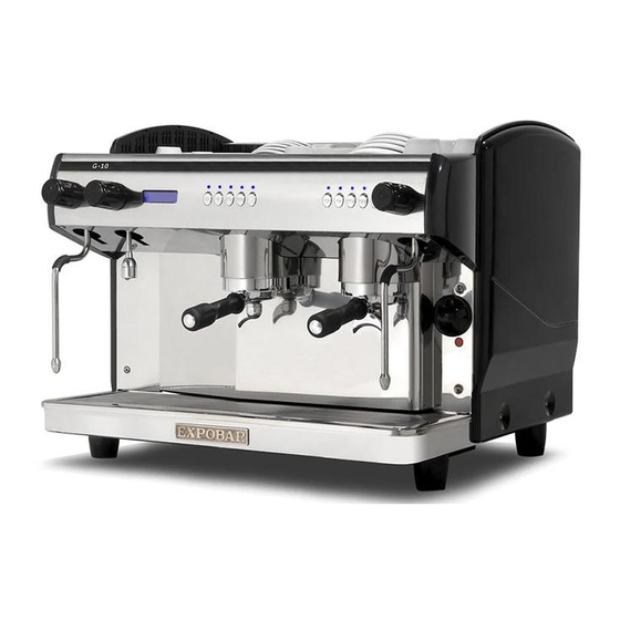
Expobar G-10 Service Manual
Espresso machine
Hide thumbs
Also See for G-10:
- Service manual (75 pages) ,
- User manual (34 pages) ,
- User manual (33 pages)
Table of Contents
Advertisement
Quick Links
Advertisement
Table of Contents

Related Manuals for Expobar G-10


Summary of Contents for Expobar G-10
- Page 1 G-10 SERVICE MANUAL SM_EN Date.: 140402...
-
Page 2: Table Of Contents
Warnings ............................................ 6 Precautions ..........................................7 Intended use ................................ 7 TECHNICAL SPECIFICATIONS ...........................8 G-10 MINI CONTROL ......................................8 Accessories..........................................8 G-10 DISPLAY CONTROL 2GR ..................................9 Accessories..........................................9 G-10 DISPLAY CONTROL 3GR ..................................10 Accessories..........................................10 OVERVIEW OF COMPONENTS ..........................11 G-10 MINI CONTROL ......................................11 G-10 DISPLAY CONTROL 2GR ..................................12... -
Page 3: Contents
Digital thermostat functions ....................................34 Connecting/disconnecting each thermostat ..............................34 Setting group temperature ....................................35 Reset parameters to factory default ..................................35 Thermostat alarms ........................................35 MESSAGES AND ALARMS ............................36 TROUBLESHOOTING ..............................37 ELECTRICAL DIAGRAMS .............................38 Complete electrical diagram: G-10 Mini 2Gr ..............................38 Secondary electrical diagram: G-10 2Gr ................................39... - Page 4 CONTENTS G-10 Electrical power diagram: G-10 2Gr 3 Boilers 230 V 1N~ ......................... 40 Electrical power diagram: G-10 2Gr 3 Boilers 400 V 3N~ ......................... 41 Electrical power diagram: G-10 2Gr 3 Boilers 230 V 3N~ ......................... 42 High current schematics G-10 ................................... 43 ELECTRICAL COMPONENTS ..........................46...
-
Page 5: Symbol Description
SYMBOL DESCRIPTION G-10 Hazard intensity levels There are three different levels of hazard intensity, identified by signal words DANGER, WARNING and IMPORTANT. The level of hazard is determined by the following definitions. Observe the statements to ensure safety, performance, prevent injury and machine damage. -
Page 6: General
GENERAL G-10 Introduction Thank you for choosing the G-10 espresso machine. We hope you enjoy it ! Read the user manual before using the machine. Keep this manual close to hand for future This manual contains important instructions on reference. If damaged or lost, request a copy from intended and safe use of the coffee machine. -
Page 7: Precautions
GENERAL G-10 Do not remove or disable any of the mechanical, units of the same model. Do not place other electrical or thermal protection mechanisms. heavier packages on top of the box. In case of emergency, (e.g. the machine catches fire... -
Page 8: Technical Specifications
TECHNICAL SPECIFICATIONS G-10 G-10 MINI CONTROL MODEL SPECIFICATIONS G-10 MINI CONTROL 1GR G-10 MINI CONTROL 2GR Steam wand 1 unit 1 unit Hot water outlet 1 unit 1 unit Temperature control Regulated by pressure switch Regulated by pressure switch Temperature control by group... -
Page 9: Display Control 2Gr
TECHNICAL SPECIFICATIONS G-10 G-10 DISPLAY CONTROL 2GR MODEL SPECIFICATIONS G-10 DISPLAY CONTROL G-10 3 BOILERS DISPLAY CONTROL 2GR Steam wand 2 units 2 units Hot water outlet 1 unit 1 unit Temperature control PID regulation PID regulation Temperature control by group... -
Page 10: Display Control 3Gr
TECHNICAL SPECIFICATIONS G-10 G-10 DISPLAY CONTROL 3GR MODEL SPECIFICATIONS G-10 DISPLAY CONTROL G-10 4 BOILERS DISPLAY CONTROL 3GR Steam wand 2 units 2 units Hot water outlet 1 unit 1 unit Temperature control PID regulation PID regulation Temperature control by group... -
Page 11: Overview Of Components
OVERVIEW OF COMPONENTS G-10 Front view of the machine G-10 MINI CONTROL Drink ON/OFF switch Hot water tap buttons Steam tap Hot water outlet Steam wand Porta-filter Heater element lamp Boiler pressure Brewing group gauge... -
Page 12: Display Control 2Gr
OVERVIEW OF COMPONENTS G-10 Front view of the machine G-10 DISPLAY CONTROL 2GR Hot water tap Digital temperature Steam tap control Drink Steam tap Display Steam wand buttons Heater element lamp Porta-filter Steam wand Brewing ON/OFF switch Hot water outlet... -
Page 13: Display Control 3Gr
OVERVIEW OF COMPONENTS G-10 Front view of the machine G-10 DISPLAY CONTROL 3GR Hot water tap ON/OFF switch Digital temperature control Drink Steam tap buttons Display Steam tap Steam wand Porta-filter Heater element lamp Hot water outlet Steam wand Brewing... -
Page 14: Dimension Sketch
DIMENSION SKETCH G-10 G-10 MINI CONTROL Model 530 mm 460 mm 590 mm 74 mm G-10 MINI 1Gr G-10 MINI 1Gr 530 mm 460 mm 590 mm 124 mm Tall Cup G-10 MINI 2Gr 530 mm 460 mm 590 mm... -
Page 15: Display Control 2Gr
DIMENSION SKETCH G-10 G-10 DISPLAY CONTROL 2GR Model 530 mm 680 mm 590 mm 74 mm G-10 2Gr G-10 2Gr 530 mm 680 mm 590 mm 124 mm Tall Cup G-10 2Gr 3 Boilers 530 mm 680 mm 590 mm... -
Page 16: Display Control 3Gr
DIMENSION SKETCH G-10 G-10 DISPLAY CONTROL 3GR Model 530 mm 980 mm 590 mm 74 mm G-10 3GR G-10 3GR 530 mm 980 mm 590 mm 124 mm Tall Cup 530 mm 980 mm 590 mm 74 mm G-10 3Gr Boilers... -
Page 17: Transport
TRANSPORT G-10 Packaging The machine is shipped in a unique carton box which uses expanded polystyrene paddings. The machine box is provided with conventional symbols that can be perfectly visible during the handling and storage tasks. The machine box must stay in a vertical position during the transport. Do not tip or try to place the box tilted sideways in any way. -
Page 18: Electrical Connection
INSTALLATION AND START UP G-10 Electrical connection The coffee machine should only be connected to the power supply by qualified personnel. The following safety instructions should be followed at all times: Check that the electrical specifications on the ratings plate match the specifications of the power supply at the point of installation. -
Page 19: Water Connection
INSTALLATION AND START UP G-10 Water connection The Installation of the machine to a water mains connection must be done by a qualified person. Rinse around 20 liters of water from the main water supply before connecting the machine to the water connection. -
Page 20: Cleaning And Care
CLEANING AND CARE G-10 Coffee machine cleaning Important: To obtain the best efficiency, quality and performance of the machine, you should always follow the cleaning and care instructions provided in this manual. Turn off the power switch when cleaning the exterior of the machine. -
Page 21: Cleaning The Brewing Group And Porta-Filter
CLEANING AND CARE G-10 Cleaning the Brewing group and porta-filter Unlock and remove the porta-filter from the group head. Place the cleaning membrane in the filter basket. Fill the filter basket with professional cleaning powder for espresso coffee machines. Lock the porta-filter into the group head. -
Page 22: Cleaning The Gasket And Shower Plate
CLEANING AND CARE G-10 Cleaning the gasket and shower plate Cleaning the gasket When placing the porta-filter filled with grinded coffee into the brewing group, left overs will accumulate in the closing surface. If these remains are excessive it can prevent a good closing between the porta-filter and the group head.Moreover, these remains can even block the dispensing of water through the group head. -
Page 23: Additional Handling Of The Machine
CLEANING AND CARE G-10 Additional handling of the machine Important: Avoid placing wet cups directly on the cup shelf, it may drip into the machine and cause machine damage. Remove and insert the porta-filter gently. Never use excessive force to try to close the porta-filter. -
Page 24: Programming
PROGRAMMING G-10 Electronic control panel Button functions Here is some of the additional functions that the electronics offers: Volume control of four different espresso drinks per brewing group. Time-controlled hot water dispensing. (if available) Automatic filling and level control of the boiler. -
Page 25: Additional Functions Accessible From The Display
PROGRAMMING G-10 Additional functions accessible from the display CREM XXX ºC hh:mm Programmable pub- Current time licity EXPOBAR SELECT Boiler temperature Machines equipped with a display include the following additional functions: Automatic daily on/off timer (stand-by). Clock settings (current time and date). -
Page 26: Accessing The Counters
PROGRAMMING G-10 Accessing the counters With the machine switched ON, hold down the Continuous Dispensing button Dose programming for over 8 seconds (until the "Dose programming" menu is displayed, see fig. 02). Select 30 s Fig. 02 Hold down the Continuous Dispensing button until the "Set clock"... -
Page 27: Service: Service Alert
PROGRAMMING G-10 Service: service alert This counter displays the number of coffees/infusions (individual servings) dispensed by Service the machine (see fig. 06). NNNN How to access it: Press the Continuous Dispensing button when the litre Fig. 06 counter is displayed. -
Page 28: Service Programming
SERVICE PROGRAMMING G-10 Reset parameters to factory default To reset the control panel settings to the factory default: Data reset Switch off the machine at the power switch. completed Press and hold down the '1 Short Espresso' , 2 Short Espressos Fig. -
Page 29: Name 1: Programming The Publicity Display (Upper Line)
SERVICE PROGRAMMING G-10 Name 1: Programming the publicity display (upper line) The display comprises two rows of 16 characters. The publicity messages displayed on Name 1 these two lines can be edited in this menu (see fig. 13) and the next one. -
Page 30: Dose Programming
SERVICE PROGRAMMING G-10 Dose programming This menu is used to enable/disable coffee-dose programming (see fig. 16). Dose programming When disabled, users are not able to modify the doses (as described in the user Enabled/Disabled manual). This mode is intended to prevent users setting inappropriate doses. -
Page 31: Electronic Steam Wand
SERVICE PROGRAMMING G-10 Electronic steam wand If the machine has an electronic steam wand (no manual steam tap), this menu is used Steam tap Gr. to select (via the Continuous Dispensing button) which button panel will control the wand. Fig. 19... -
Page 32: Grinding Alert
SERVICE PROGRAMMING G-10 Grinding alert This setting is used to enable/disable the coffee-dispensing monitor (see fig. 22). This Grinding alert analyses dispensing speed and, depending on this value, indicates if the coffee is too Enabled/Disabled finely or too coarsely ground. If the dispensing speed is between the pre-established values, the "OK"... -
Page 33: Maintenance Cycles
SERVICE PROGRAMMING G-10 Maintenance cycles This menu sets the number of coffees dispensed per maintenance cycle (before Maintenance cycles replacing shower plates, gaskets, etc.). When the dispensing counter reaches the N000 number set (see fig. 26), the "Service" message will be displayed. -
Page 34: Multi-Boiler Programming
G-10 Digital thermostat functions In multi-boiler models, each dispensing group has an independent digital boiler-temperature adjustment system. The following multi-boiler G-10 models are available: 2 dispensing groups and 3 boilers. 3 dispensing groups and 4 boilers. Temperature is controlled by a digital thermostat to ensure optimal temperature stability at each group spout. -
Page 35: Setting Group Temperature
MULTI-BOILER PROGRAMMING G-10 Setting group temperature To adjust the group temperature maintained by the thermostat, follow the instructions below with the machine turned on and the thermostat connected: Briefly press the button. The thermostat will display the "PrG" message Fig. 31 (see fig. -
Page 36: Messages And Alarms
MESSAGES AND ALARMS G-10 Alarm Fault in volumetric counter N / Flow fault detected in counter N Counter Vol. Gr. N Time-out alarm Check that the machine is receiving water. Boiler filling Sensor fault Temperature gauge fault Service the machine. -
Page 37: Troubleshooting
TROUBLESHOOTING G-10 The following checks can be carried out by users once the machine has been turned off and disconnected from the power supply. For all other non-specified machine faults, disconnect the machine from the power supply and immediately contact authorised and qualified service personnel. -
Page 38: Electrical Diagrams
ELECTRICAL DIAGRAMS G-10 Complete electrical diagram: G-10 Mini 2Gr... -
Page 39: Secondary Electrical Diagram: G-10 2Gr
ELECTRICAL DIAGRAMS G-10 Secondary electrical diagram: G-10 2Gr... -
Page 40: Electrical Power Diagram: G-10 2Gr 3 Boilers 230 V 1N
ELECTRICAL DIAGRAMS G-10 Electrical power diagram: G-10 2Gr 3 Boilers 230 V 1N~... -
Page 41: Electrical Power Diagram: G-10 2Gr 3 Boilers 400 V 3N
ELECTRICAL DIAGRAMS G-10 Electrical power diagram: G-10 2Gr 3 Boilers 400 V 3N~... -
Page 42: Electrical Power Diagram: G-10 2Gr 3 Boilers 230 V 3N
ELECTRICAL DIAGRAMS G-10 Electrical power diagram: G-10 2Gr 3 Boilers 230 V 3N~... -
Page 43: High Current Schematics G-10
ELECTRICAL DIAGRAMS G-10 High current schematics G-10 230V 1N~ HEATING ELEMENT 2500W REF. 60901001 I.L. REF. 60900035 N - O L1 - R R.E. R.E.A. (90-280V) REF. 38025001 REF.60800100 230V 1N~ HEATING ELEMENT 3050W- 2GR REF. 60901001 REF. 60900001 N - O L1 - R R.E.C. - Page 44 ELECTRICAL DIAGRAMS G-10 High current schematics G-10 230V 1N~ HEATING ELEMENT 3050W- 2GR B2’ - B2’ REF. 60900001 REF. 60901001 1.G. N - O L1 - R R.E.A. (90-280V) R.E. REF.60800100 REF. 38027000 HEATING ELEMENT 4500W - 2GR The black wire is painted blue at secondary circuit B2’...
- Page 45 ELECTRICAL DIAGRAMS G-10 High current schematics G-10 400V 2N~ HEATING ELEMENT 4000W- 3GR C3’ - C3’ REF. 60900002 REF. 60901001 1.G. N - O L1 - R L2 - S REF. 38040000 R.E.C. R.E.C. (3-32V) (3-32V) REF.60800101 REF.60800101 400V 3N~ HEATING ELEMENT 6000W- 3GR C3’...
-
Page 46: Electrical Components
ELECTRICAL COMPONENTS G-10 G-10 Mini 2Gr View Part No. Description C60100310 Switchboard 1D5 G-10 220V Probe C60100410 Control Board 3D5 Xlc C60800100 Static Relay C60900035 Switch Red Components common to all models View Part No. Description C60800103 Relay Protection Cover... - Page 47 ELECTRICAL COMPONENTS G-10 G-10 2GR / 3GR View Part No. Description C60100034 Switchboard 3D5 Disp Lux C60101046 Button Battery D20 Cr2032 C60800101 Static Relay 4-32 C60100301 Display Control Mega/G10 New Elegan C60100305 Black G-10 Display Membrane C10200125 Digital Thermostat 230V...
-
Page 48: Detail Drawings
DETAIL DRAWINGS G-10 G-10: Housing parts Drawing... - Page 49 G-10: Housing parts Part list Description POS. Machine Part No. Description POS. Machine Part No. C17020110 Supp front panel G-10 Minicon 1GR C20000145 Inox Drip Tray Mini MINI MINI C17120116 Supp front panel G-10 Minicon 2GR 2 GR C20000166 Inox Drip Tray 2Gr...
-
Page 50: Mini 2Gr: Water System
DETAIL DRAWINGS G-10 G-10 Mini 2Gr: water system Drawing... - Page 51 DETAIL DRAWINGS G-10 G-10 Mini 2Gr: water system Part list POS. Part No. Description C15000370 Tap Steam Eleg./Mega Comp 4H Bf C60000062 D-40 One Reading Manometer Orman C35040117 4Ltrs Grinder's Steam Pipe C35110530 Pipe Manometer C15000050 Group Espresso Preass C35040006...
-
Page 52: 2Gr: Water System
DETAIL DRAWINGS G-10 G-10 2Gr: water system Drawing... - Page 53 DETAIL DRAWINGS G-10 G-10 2Gr: water system Part list POS. Part No. Description C35900020 30Cm Hose C15000370 Tap Steam Eleg./Mega Comp 4H Bf C35040117 4Ltrs Grinder's Steam Pipe C35110465 Pipe Water Filling 2Gr Mc C15000330 Tap Hot Water Complete C35110005...
-
Page 54: 2Gr 3 Boilers: Water System
DETAIL DRAWINGS G-10 G-10 2Gr 3 Boilers: water system Drawing... - Page 55 DETAIL DRAWINGS G-10 G-10 2Gr 3 Boilers: water system Part list POS. Part No. Description C15000370 Tap Steam Eleg./Mega Comp 4H Bf C15000330 Tap Hot Water Complete C35040117 4Ltrs Grinder's Steam Pipe C35040118 Pipe Water Filling Mini C15000050 Group Espresso Preass...
-
Page 56: Mini: Boiler Assembly
DETAIL DRAWINGS G-10 G-10 Mini: boiler assembly Drawing... - Page 57 DETAIL DRAWINGS G-10 G-10 Mini: boiler assembly Part list POS. Part No. Description C15100016 Copper Boiler 2Gr 6Lt C15100018 Boiler Copper 1Gr 6L C50010050 3/8 Boiler's Connector Teflon Gaske C38025001 2500W-230V- 6LTRS.COPPER ELEMENT C25093320 Hexagonal Head Screew 8X20 Din 933...
-
Page 58: 2Gr: Boiler Assembly
DETAIL DRAWINGS G-10 G-10 2Gr: boiler assembly Drawing... - Page 59 DETAIL DRAWINGS G-10 G-10 2Gr: boiler assembly Part list POS. Part No. Description C15100020 Boiler 2Gr 11Lts. C65000110 Cn10 Ptfe Ce Safety Valve C30000315 Bling Plug 1/8 Female C50010030 40*52*2 Element Teflon Gasket C38027000 3050W.230V- 2Gr Element C30834503 3450 W 230 V 2 GR ELEMENT...
-
Page 60: 2Gr 3 Boilers: Boiler Assembly (Main Boiler)
DETAIL DRAWINGS G-10 G-10 2Gr 3 Boilers: boiler assembly (main boiler) Drawing... -
Page 61: G-10 2Gr 3 Boilers: Boiler Assembly (Main Boiler)
DETAIL DRAWINGS G-10 G-10 2Gr 3 Boilers: boiler assembly (main boiler) Part list POS. Part No. Description C60100076 Temp. Probe + Susp. Steam Pipe Icd C30000003 Reducer Male-Female-3/8 - 1/4 C30000290 Plug M 3/8 C65000200 Non Suction Valve C30000315 Bling Plug 1/8 Female... -
Page 62: 2Gr 3 Boilers: Boiler Assembly (Group Boiler)
DETAIL DRAWINGS G-10 G-10 2Gr 3 Boilers: boiler assembly (group boiler) Drawing... -
Page 63: G-10 2Gr 3 Boilers: Boiler Assembly (Group Boiler)
DETAIL DRAWINGS G-10 G-10 2Gr 3 Boilers: boiler assembly (group boiler) Part list POS. Part No. Description C30000220 Cone Injector 1/4 C50010020 13.2*18.2*2.5 1/4 Teflon Gasket C25091210 Allen Screw 4X12 Din-912 C10200110 Office Thermostat 16 A C30000290 Plug M 3/8... -
Page 64: G-10: Rotary Pumps
DETAIL DRAWINGS G-10 G-10: Rotary pumps Drawing... - Page 65 O-Ring 8 X 1.9 C65000010 Retention Valve C60000030 Pump (Crem Special Treatment) Piston Bypass Pump (Tec) C60000031 C60000033 Pump Rotary Compact CESCMPS00 Motor&Pump Ass Std CESCMPE00 MOTOR&PUMP ASS ECO Note: Part No. C30400055 and CESCMPE00 apply to the G-10 Mini models.
-
Page 66: Group Head
DETAIL DRAWINGS G-10 Group head Drawing... - Page 67 DETAIL DRAWINGS G-10 Group head Part list POS. Part No. Description C30200035 Long Plug 1/2 Group C50010040 21.7*25.7*2 G/C-G Teflon Gasket C70000009 Group Teflon Injector Rev3 C30200061 Group Teflon Injector Rev3 C30200026 Tefl Water Reduc. Holder 4X6x65 C25091250 Allen Screw 6*10 Din-912 Group...
-
Page 68: Portafilters
DETAIL DRAWINGS G-10 Portafilters Drawing 02 03... - Page 69 DETAIL DRAWINGS G-10 Portafilters Part list POS. Part No. Description C75000059 1 Cup Filter 6 Gr C75000037 1 Cup Filter 6,5 Gr C75000031 1 Cup Filter (7Gr) C75000050 Spout 1Cup C75000041 2 Cup Filter (14Gr) C75000060 Spout 2Cups C75000049 3 Cup Filter (21Gr)
-
Page 70: Mini 1Gr : Water Supply And Drainage Set
DETAIL DRAWINGS G-10 G-10 Mini 1Gr : water supply and drainage set Drawing Part list POS. Part No. Description C30000510 Conical Adaptor 1/4*1/4 Electron C60000100 1/4 X 1/4 Electrovalve Parker 220V C60000103 1/4 X 1/4 Electrovalve Parker 120V C50010020 13.2*18.2*2.5 1/4 Teflon Gasket... - Page 71 DETAIL DRAWINGS G-10 G-10 Mini 2Gr : water supply and drainage set Drawing Part list POS. Part No. Description C60000100 1/4 X 1/4 Electrovalve Parker 220V C60000103 1/4 X 1/4 Electrovalve Parker 120V C30100010 Hexagonal Nut 1/4 Pressostat C35040101 Mini Brass Tube For Battery...
-
Page 72: 2Gr: Water Supply And Drainage Set
DETAIL DRAWINGS G-10 G-10 2Gr: water supply and drainage set Drawing... - Page 73 DETAIL DRAWINGS G-10 G-10 2Gr: water supply and drainage set Part list POS. Part No. Description C60000105 50/60Hz 220V Solenoid Electrovalve C50000105 Large Autofill Solenoid Gasket C50000110 Small Autofill Solenoid Gasket C30000215 Conical Bend Adaptor 1/4 X 1/4 C30100010 Hexagonal Nut 1/4 Pressostat...
-
Page 74: Steam Tap
DETAIL DRAWINGS G-10 Steam tap Drawing 05 06 07... - Page 75 DETAIL DRAWINGS G-10 Steam tap Part list POS. Part No. Description C30370070 Tap Body C30370060 Close Nut C30370050 Closing Shaft M-6 C30370040 Shaft Spring C30370065 Push Cap C30370020 Shaft Ring C30370030 Gasket C30370010 Tap Fitting C30370140 Tap Fixing Nut C40000015...
-
Page 76: Hot Water Taps
DETAIL DRAWINGS G-10 Hot water taps Drawing 01 02 05 06 07... - Page 77 DETAIL DRAWINGS G-10 Hot water taps Part list POS. Part No. Description C30370070 Tap Body C30370060 Close Nut C30370050 Closing Shaft M-6 C30370040 Shaft Spring C30370065 Push Cap C30370020 Shaft Ring C30370030 Gasket C30370010 Tap Fitting C30370140 Tap Fixing Nut...
-
Page 78: Service Intervals
SERVICE INTERVALS G-10 G-10 Mini Control 1Gr & 2Gr Months (Cycles) Main components Part No. 6 (12500) 12 (25000) 18 (37500) 24 (50000) Boiler Non suction valve Replace Replace C65000200 1/4 X 1/4 Electrovalve Parker Replace C60000100 220V Check Replace Thermics Sup. -
Page 79: Display Control 2Gr & 3Gr
SERVICE INTERVALS G-10 G-10 Display Control 2Gr & 3Gr Months (Cycles) Main components Part No. 6 (12500) 12 (25000) 18 (37500) 24 (50000) Boiler Replace Replace Non Suction Valve C65000200 Solenoid Electrovalve 50/60Hz Replace C60000105 220V Check Replace Thermics Sup. Adaptor 1/2 X 1/2 C30000200 Thermics Inf. -
Page 80: Technical Support
For the warranty to be valid, the conditions for maintenance must have been followed in accordance with our instructions, proper care must have been taken and any claim against the warranty must be sent without delay. The equipment in question may not be used while awaiting service if there is any risk that the damage or defect would worsen.
Need help?
Do you have a question about the G-10 and is the answer not in the manual?
Questions and answers