
Related Manuals for Ahlborn ALMEMO 2390-5


Summary of Contents for Ahlborn ALMEMO 2390-5
- Page 1 Operating instructions Multifunction measuring instrument ® ALMEMO 2390-5 with data logger option V1.3 10.10.2005 ALMEMO 2390-5...
-
Page 2: Table Of Contents
Table of contents Operating instructions Multi-function measuring instrument ® ALMEMO 2390-5 with data logger option ® With supplementary reference to the ALMEMO Manual Table of contents Page INTRODUCTION Functions Operating controls PUTTING INTO SERVICE POWER SUPPLY Battery / rechargeable battery operation External voltage supply Switching ON / OFF, retaining stored data, reinitialization Sensor supply... - Page 3 Table of contents 6.2.6 Temperature compensation Measuring point scans and data output 6.3.1 Once-only measuring point scan 6.3.2 Cyclic measuring point scan 6.3.3 Output formats for measured value lists 6.3.4 Manual data output Averaging 6.4.1 Smoothing out measured values by means of a sliding average 6.4.2 Averaging mode 6.4.3...
-
Page 4: Introduction
Functions 1. INTRODUCTION ® The multi-function measuring instrument ALMEMO 2390-5 is a new member in our family of unique measuring devices - all equipped with Ahlborn GmbH’s ® ® patented ALMEMO connector system. The intelligent ALMEMO connector of- fers decisive advantages when connecting sensors and peripherals because all parameters are stored in an EEPROM on the connector itself;... - Page 5 Functions SENSOR PROGRAMMING ® The measuring channels are automatically programmed via the ALMEMO sen- sor connectors. However, the user can easily supplement or modify this pro- gramming via the keypad or via the interface. Measuring ranges Appropriate measuring ranges are available for all sensors with a non-linear characteristic, e.g.
- Page 6 Functions Limit values and alarm Per measuring channel two limit values can be set (1 maximum and 1 mini- mum). In the event of one of these limit values being exceeded relay output modules actuate the appropriate alarm contacts. Hysteresis is set by default to 10 digits but can also be adjusted.
- Page 7 Functions Volume flow measurement For all flow sensors not only the functions for averaging are provided but also functions for entering the cross-section and diameter of ventilating channels and for calculating the volume flow. The average flow velocity can be deter- mined roughly by scanning the whole cross-section or exactly by means of net- work measurements according to DIN.
- Page 8 Functions automatically according to date and time-of-day. The memory can be organi- zed and configured in linear or ring form. As an alternative storage medium ex- ® ternal ALMEMO connectors are also available with an EEPROM of either 128 KB capacity (sufficient for 25000 measured values) or 256 KB capacity (suffi- cient for 50000 measured values).
-
Page 9: Operating Controls
Operating controls 1.2 Operating controls (1) ON/OFF-switch ( 3 ) down (2) Measuring inputs M0, M1, M2 M0, M1, M2 for all ALMEMO-sensors Function channel differential M10 .. M33 Additional channels (3) Output sockets A1, A2 A1 V24-interface (ZA 1909-DK5/DKL) Ethernet (ZA 1945-DK) RS 422 (ZA 5099-NVB) Relay-trigger-cable (ZA 1000-EAK) - Page 10 Operating controls (6) FUNCTION KEYS PROG, +/-, Input of programming parameters PROG, CLEAR Clear data, set measured value to zero PROG, , PROG Adjust measured value Select measured value, measuring point START/ STOP Start and stop a measuring operation MANU/ PRINT Manual measuring point scan, data output FUNCTION...
-
Page 11: Putting Into Service
Putting into service 2. PUTTING INTO SERVICE 1. Connect transducer to sockets M0 to M2 (2); (see Section 4). 2. Ensure that the power supply is provided via 9-volt battery or mains adapter; (see Sections 3.1, 3.2). 3. To switch ON, push slide switch (1) located on left side of device upwards; (see Section 3.3). -
Page 12: Power Supply
Power supply 3. POWER SUPPLY As power supply for the measuring instrument there are the following possibili- ties: 9-volt batteries IEC 6F22 ZB 2000-B9 9-volt rechargeable battery pack, same with charger integrated in the connector ZB 2000-A9, ZB 2000-LS mains adapter 12 V / 200 mA ZB 2290-NA external power supply, connecting cable ZB 2290-UK... -
Page 13: External Voltage Supply
Power supply Tips on how to handle batteries correctly: Never leave used dead batteries in the device ! If the device is likely to be unused for a relatively long time, remove the batteries ! A leaking battery represents a health hazard and may also destroy the de- vice. -
Page 14: Switching On / Off, Retaining Stored Data, Reinitialization
Power supply 3.3 Switching ON / OFF, retaining stored data, reinitialization The ON / OFF slide switch (1) located on the left side of the device has two switch positions : To switch ON, push the slide switch (1) located on the left side of the device upwards. -
Page 15: Connecting The Transducers
4.2 Measuring inputs and additional channels Measuring instrument ALMEMO 2390-5 has three input sockets M0, M1, M2 (2) ® to which initially measuring channels M0, M1, M2 are allocated. ALMEMO sensors can, however, if necessary, provide up to four channels. - Page 16 M1-M0 A2 A1 2390-5 The three analog inputs on the ALMEMO 2390-5 are electrical- ly isolated by means of photovoltaic relays; the maximum po- tential difference permitted between them is 50 V DC or 60 V AC. Sensors combined within one connector and sensors with their own power supply, however, are electrically intercon- nected and must therefore be operated in isolation.
-
Page 17: Display And Keypad
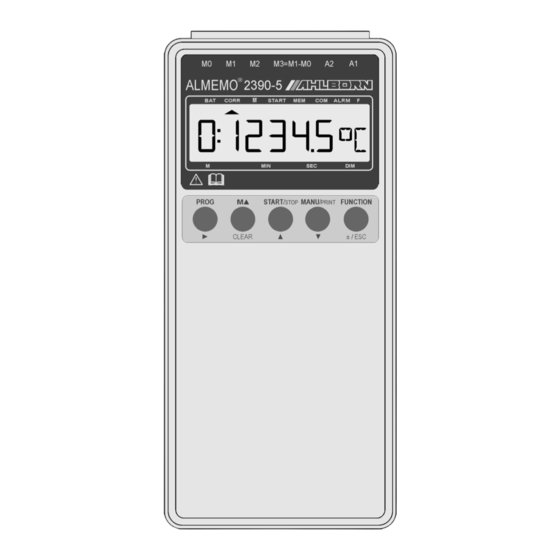
Display and keypad 5. DISPLAY AND KEYPAD 5.1 Display The display (5) on measuring instrument ALMEMO 2390-5 comprises an LCD with 6½ x 7-segment characters, two 16-segment characters, a battery symbol, and seven arrows to indicate the operating status. CORR... - Page 18 Display and keypad Special operating states Segment test for display This is performed automatically each time the device is switched ON. Voltage supply: below 7 volts: -Symbol lights up 1:L o b A t below 6 volts: 1:U - Lo Sensor supply power shorter than UMIN: ...
-
Page 19: Function Selection And Activation
Display and keypad 5.2 Function selection and activation Measuring instrument ALMEMO 2390-5 provides a wide variety of functions for controlling measuring sequences, for acquiring, averaging, monitoring, and sa- ving measured values, for outputting data to various peripheral equipment, and for scaling, adjusting, and correcting sensors, etc.. Since these functions will not be needed by the normal user all at once, they can be activated in various ways on an application-specific basis. - Page 20 Display and keypad Abbrev. Memory Funktions Value Activation Hold down FUNCTION key 1: 023.4 TC Temp. compensation Device first time it is pressed 01:113.2 MF Default Memory free (option S) Device 00:15:00 CY Default Device Cycle Hold down FUNCTION key 12:34:56 T Time of day Device...
-
Page 21: Keypad
Display and keypad Language setting The function abbreviations can be shown in any one of three languages. You can switch between languages in theDISPLAYMODE ´DM´ function, which can be activated as and when necessary by holding down the FUNCTION key the first time it is pressed;... -
Page 22: Data Input
Display and keypad 5.4 Data input Numeric parameters are programmed as follows : FUNCTION Select the desired function by pressing the FUNCTION key Start programming by pressing the PROG key. PROG The front digit flashes and can now be changed. Increment the digit by pressing the key . -
Page 23: Measuring Operations
6.1 Measuring point scanning and meas. point display The ALMEMO 2390-5, unlike previous instruments, is set by default to semi- continuous measuring point scanning; i.e. all measuring points are continuously scanned and the measured values thus acquired can be called up at any time, even if they depend on other channels (e.g. -
Page 24: Differential Measurement
Measuring operations 6.1.2 Differential measurement If there are two sensors with the same units and same decimal point position connected at measuring points M0 and M1, the difference M1 - M0 appears au- tomatically below measuring point M3. The sensors are electrically isolated by means of photovoltaic relays. -
Page 25: Setting The Measured Value To Zero
Measuring operations 6.2.1 Setting the measured value to zero, It is possible - a very useful function - to zero the measured value at certain lo- cations or at certain times in order then to observe the deviation from this refe- rence value. - Page 26 Measuring operations In the ´AJ´ function the measured value appears in the display, initially flashing; this should be the measured value expected after adjustment, i.e. either the normal 0.0 or a scaled value, e.g. 7.00 for pH probes. So long as the corrected measured value is shown (rather than the actual measured value), the CORR arrow appears in the display.
-
Page 27: Entering A Setpoint
Measuring operations 6.2.3 Entering a setpoint A setpoint can be entered in much the same way as gain adjustment (described in the previous section). If you save defined calibration values other than the zero-point, you can, by entering the setpoint, automatically correct or scale a measured value. -
Page 28: Atmospheric Pressure Compensation
Measuring operations used for all thermocouple types; however, they require two measuring chan- nels. ´#J´ is programmed in the comments; this ensures that the temperature sensor integrated in the connector is used for cold junction compensation. 6.2.5 Atmospheric pressure compensation Some measured variables depend on the ambient atmospheric pressure (see Section 7.7, measuring range list ´with PC´) with the effect that pronounced de- viations from normal pressure (1013 mbar) may lead to measuring errors. -
Page 29: Measuring Point Scans And Data Output
Measuring operations FUNCTION 1: 1 8 0.0 Select by pressing key ... Enter °C s. Sec. 5.4 6.3 Measuring point scans and data output Measuring point scans can be used to acquire and then evaluate data from all active measuring points at particular times (for the purposes e.g. of averaging, outputting to the interface, or saving to memory). -
Page 30: Output Formats For Measured Value Lists
Measuring operations STOP The cyclic measuring operation is started by pressing theSTART/ key; the ´START´ arrow should light up continuously. If a peripheral device is con- nected, the measured values are output cyclically and the ´COM´ arrow should appear. There is a wide variety of output formats available (see Section 6.3.3). For the associated printouts please refer to the Manual Section 6.6.1. -
Page 31: Manual Data Output
CY PRINT CYCLE: 00:06:00 CYCLE TIME TM TIME: 12:34:00 DA DATE: 01.02.99 DATE AMR ALMEMO 2390-5 BAUD RATE s. Hb. 6.2.3 CH RANGE LIM-MAX LIM-MIN BASE D FACTOR EXP AVG COMMENT (Senor 01:Ntc +040.00 - - - - - - °C 1.0123 E+0 - - - Temperature programming) 02:°o H +0060.0 +0020.0 - - - %H - - - E+0 - - - Humidity... -
Page 32: Averaging
Measuring operations 6.4 Averaging The average value of the measured value is required for various applications : e.g. the average flow velocity in a ventilation channel smoothing of a widely fluctuating measured value (e.g. wind, pressure etc.) hourly or daily average values of weather data (temperature, wind etc.) as above, for consumption values (current, water, gas, etc.) The average value of a measured value is obtained by adding together a se-... -
Page 33: Averaging Over The Time From Start To Stop
Measuring operations ® If a sensor with an ALMEMO connector is connected, the following modes can be set by pressing keys PROG, , PROG : Function Display No averaging: - - - - Continuous averaging from start to stop (see 6.4.3) C o n t or over single measurements, if not started (see 6.4.4): C Y C L... -
Page 34: Averaging Over Single Measurements
Measuring operations Section 3.5.5) or for a whole measuring operation (also with cyclic scanning), the averaging mode to be set is ´Cont´ (see Section 6.4.2). 1. Select the AVERAGE VALUE function ´MW´ by pressing the FUNCTION key. The averaging start and stop can if necessary also be selected in any other function (e.g. -
Page 35: Volume Flow Measurement
Measuring operations 6.4.5 Volume flow measurement To determine the volume flow VF in ventilating channels multiply average flow velocity ¯ v by cross-section area CS.: VF = ¯ v 0.36 VF = m /h, ¯ v = m/s, CS = cm For approximate air volume measurements at air vents and gratings the aver- age flow velocity can be determined by means of time-based averaging. -
Page 36: Cyclic Averaging
Measuring operations Entering the cross-section The cross-section area CS can be entered in the ´Flow´ channel either directly in the ´CS´ function up to a maximum of 32000 cm2 or as diameter in the ´DN´ function up to a maximum of 2000 mm; (see Section 5.4). When the function channel ´Flow´... -
Page 37: Averaging Over Several Measuring Points
Mb1. For this purpose avera- ging mode is not necessary. 6.5 Measured value memory (option S) Measuring instrument ALMEMO 2390-5 is also available with the option “S” as ® a data logger. The basic information on saving data in ALMEMO devices is provided in the Manual, Section 6.9. -
Page 38: Measured Value Recording
Measuring operations re, and evaluated by computer over a read interface (ZA 1409-SLG0) on a completely device-independent basis. Old read cable ZA 1409-SLK does not support operation with a ring memory configuration; i.e. it cannot be used to read out measured data saved to ring memory. -
Page 39: Measured Value Output
Measuring operations Starting and stopping with start date and time-of-day, and end date and time-of-day A measuring series can be started and stopped automatically at specified ti- mes. The start date and time-of-day and end date and time-of-day can be free- ly programmed - providing these functions have been activated (see Section 5.2). -
Page 40: Sleep Mode
Measuring operations Delete memory When the PROG key is pressed, the symbol ´SClr´ starts flashing. Only if you now press the Clear key will the memory content be deleted PROG `S C L r´ delete memory by pressing the key: CLEAR 6.5.4 Sleep mode For long-term monitoring with more prolonged cycles (i.e. -
Page 41: Sensor Programming
Sensor programming 7. SENSOR PROGRAMMING ® ® Since on ALMEMO devices all sensor programming is stored in the ALMEMO connector, the user will not normally need to reprogram. Programming will only be necessary e.g. if sensor errors are corrected, if your own sensors are sca- led, or if certain limit values are stipulated;... -
Page 42: Limit Values
Sensor programming Locking mode function ´LM´ FUNCTION 1:0 0 0 5 Select by pressing key: ... Enter as per Sec. 5.4 In the display, in front of the locking mode, you should see output function, ele- ment flags and multiplexer position - assuming these have been programmed (see Manual, Section 6.10.2/3/4). -
Page 43: Scaling, Decimal Point Setting
Sensor programming 7.5 Scaling, decimal point setting To display the electrical signal of a sensor as measured value in its physical si- ze, it is nearly always necessary to perform decimal point shift, zero-point cor- rection, and multiplication with a factor. To perform these steps the functions EXPONENT ´EX´, BASIS ´BA´, and FACTOR ´FA´... -
Page 44: Selecting The Measuring Range
Sensor programming All upper-case and lower-case letters, special characters °, °, Ω, %, [, ], *, -, =, ~, and space (_) can be used. The units are shown as two 16-segment cha- racters after the measured value or programming value. To modify the units go to the menu (see Section 6.2) in the MEASURED VA- LUE function and press the keys PROG and then ;... - Page 45 Sensor programming range appears in the display, programming can be completed by pressing the PROG key again and this data is transferred and saved to the connector. All programming values for this measuring point are deleted. RANGE function ´R´ FUNCTION 1: N i C r Select by pressing key: Channel M1, range NiCr-Ni...
- Page 46 Sensor programming Sensor / connector Display Transducer Measuring range Units Ω ZA 9000-FS 0.00... 500.00 Ohms Ω Ohn1 ZA 9003-SS3 0.000... 50.000 FrEq ZA 9909-AK 0... 25000 Frequency PULS ZA 9909-AK 0... 65000 Pulses Digital input ZA 9000-EK2 0.0... 100.0 diGi Digital interface ZA 9919-AKxx...
- Page 47 Sensor programming Sensor / connector Display Transducer Measuring range Units A[n] Average val. M(n) of Mb2 to Mb1 any S[n] Sum S(n) of Mb2 to Mb1 S[t] Total pulses S(t) of Mb1 ZA 9909-AK2 0... 65000 S[P] Pulses / print cycle of Mb1 ZA 9909-AK2 0...
-
Page 48: Special Meas. Ranges, Linearization, Multi-Point Calibration
Analog output The measured value is then no longer displayed, scanned, and output but the programming is retained intact. Reactivating the measuring channel: PROG PROG Function: RANGE ´R´ keys : If the channel was previously deactivated, then it is now reactivated with all pro- gramming values intact. -
Page 49: Analog Output
Device programming 8. ANALOG OUTPUT For the analog registration of the selected measuring point you can, to sockets A1 or A2, connect either an analog output cable ZA 1601-RK (see Manual, Section 5.1.1) without electrical isolation or a relay trigger analog adapter ZA 8000-RTA (see Manual, Section 5.1.3) with electrically isolated analog output. -
Page 50: Device Programming
(see Section 9.2). 9.1 Date and time-of-day The ALMEMO 2390-5 incorporates an integrated real-time clock with date and time-of-day for logging measuring times. This real-time clock is buffered by means of the device battery with the effect that date and time-of-day are re- tained even after switching off. -
Page 51: Device Address And Networking
Trouble shooting interface module !). BAUD RATE function ´BR´ U n 9 6 0 0 Select by pressing key FUNCTION.. Example: Output to interface ´U´, in ´side-by-side´ format, 9600 baud To enter this information press thePROG key twice, then set the baud rate by means of the keys, and then program by pressing thePROG key once more. -
Page 52: Trouble-Shooting
Electromagnetic compatibility 10. TROUBLE - SHOOTING ALMEMO 2390-5 measuring instruments can be configured and programmed in many versatile ways. These measuring instruments are suitable for con- necting a wide variety of very different sensors, additional measuring instru- ments, alarm signaling devices, and peripheral equipment. Given these nu- merous possibilities the devices may in certain circumstances not behave quite as expected. - Page 53 Technical data Test data transmission by means of a terminal (AMR-Control, WIN- Control, WINDOWS-Terminal) : Address the device using its as- signed device number Gxy (see Manual, Section 6.2.1), Check the programming by means of P15 (see Manual, Section 6.2.3), Test the transmit line by entering a cycle with command ´Z123456´...
- Page 54 Product overview Technical data (s.a. Hb. 2.2) ® Measuring inputs : Three ALMEMO sockets ® for ALMEMO flat connectors Channels : 4 channels / sensor maximum (measuring and function channels, depending on sensor type) 4 function channels in device A/D converter : delta - sigma, 16-bit, 2.5 / 10 meas.
-
Page 55: Product Overview
Index Product overview Order No. Multi-function measuring instrument ALMEMO 2390-5 3 inputs, maximum 16 channels, 5 keys, cascadable interface MA 2390-5 Option S : Measured value memory 32-KB, internal or external on memory connector MA 2390-5S 8 measuring ranges for refrigerants... - Page 56 Index INDEX Keyword Section Page Additional channels Analog output - start / end Atmospheric pressure compensation 6.2.5 Averaging Averaging mode 6.4.2 Averaging over cyclic measuring point scans 6.4.6 Averaging over manual single measurements 6.4.4 Averaging over several measuring points 6.4.7 Averaging over time 6.4.3 Base value...
- Page 57 Index Keyword Section Page Element flags Exponent External voltage supply Factor Final value adjustment of force transducers 6.2.3 Function abbreviations 1.2, 5.2 10, 19 Function activation Function display 5.1, 5.2 Function keys 1.2, 5.3 10, 21 Function printouts 6.3.4 Function selection Functions 6.2.2 Gain adjustment...
- Page 58 Appendix Keyword Section Page Output function POWER SUPPLY Print cycle factor 6.4.6 Product overview PUTTING INTO SERVICE Rechargeable battery operation : Reference channels 4.2, 7.7 16, 47 Reinitialization Representatives Reset Retaining stored data 6.3.2 Saving all measuring points, cyclic Saving all measuring points, manually, once-only 6.3.1 Scaling, analog output Scaling, measured value...
- Page 59 Appendix Your contact partners ALMEMO 2390-5...
- Page 60 Appendix ALMEMO 2390-5...
Need help?
Do you have a question about the ALMEMO 2390-5 and is the answer not in the manual?
Questions and answers