Table of Contents
Advertisement
User'
User' s s s s s
User'
User'
User'
Manual
Manual
Manual
Manual
Manual
SiS
SiS
661FX
661FX
SiS
SiS
SiS 661FX
661FX mainboard
661FX
for Intel Socket 478 processor
for Intel Socket 478 processor
for Intel Socket 478 processor
for Intel Socket 478 processor
for Intel Socket 478 processor
TRADEMARK
All products and company names are trademarks or registered
trademarks of their respective holders.
These specifications are subject to change without notice.
mainboard
mainboard
mainboard
mainboard
Manual Revision 1.0
April 05, 2004
Advertisement
Table of Contents

Related Manuals for EPOX SiS 661FX


Summary of Contents for EPOX SiS 661FX
- Page 1 Manual Manual Manual Manual Manual 661FX 661FX mainboard mainboard SiS 661FX 661FX 661FX mainboard mainboard mainboard for Intel Socket 478 processor for Intel Socket 478 processor for Intel Socket 478 processor for Intel Socket 478 processor for Intel Socket 478 processor...
- Page 2 DISCLAIMER OF WARRANTIES: THERE ARE NO WARRANTIES WHICH EXTEND BEYOND THE DESCRIPTION ON THE FACE OF THE MANUFACTURER LIMITED WARRANTY. THE MANUFACTURER EXPRESSLY EXCLUDES ALL OTHER WARRANTIES, EXPRESS OR IMPLIED, REGARDING ITS PRODUCTS; INCLUDING ANY IMPLIED WARRANTIES OF MERCHANTABILITY, FITNESS FOR A PARTICULAR PURPOSE OR NONINFRINGEMENT.
-
Page 3: Table Of Contents
Table of Contents Page Section 1 Introduction Package Contents ............1-1 Intel Pentium 4 Processors......... 1-2 Ultra ATA66/100/133 ..........1-2 Hardware Monitoring ..........1-2 LAN ................1-2 I/O Shield Connector ..........1-3 Power-On/Off (Remote) ..........1-3 System Block Diagram ..........1-4 Section 2 Features Mainboard Features ........... - Page 4 Advanced BIOS Features .......... 4- 3 Advanced Chipset Features ........4- 6 Integrated Peripherals ..........4- 9 Power Management Setup ......... 4- 14 PNP/PCI Configuration Setup ........4- 18 PC Health Status ............4- 20 Power BIOS Features ..........4- 21 Defaults Menu ............
-
Page 5: Introduction
Introduction Section 1 INTRODUCTION Package Contents Contents Optional Items A. Mainboard G. COM port cable B. User’s manual H. Extra USB2.0 port cable C. Floppy disk drive cable I. S/PDIF Module D. HDD drive cable If you need the optional item, please contact your dealer for assistance. -
Page 6: Intel Pentium 4 Processors
Introduction Intel Pentium 4 processors ® ® The Pentium 4 processor is designed to deliver performance across applications and usages where end-users can truly appreciate and experience the performance. These applications include Internet audio and streaming video, image processing, video content creation, speech, 3D, CAD, games, multimedia, and multi-tasking user environments. -
Page 7: I/O Shield Connector
Introduction I/O Shield Connector The I/O back panel for this mainboard is shown below (Figure 1). When installing the mainboard into the computer case, use the bundled I/O shield to protect this back panel. RJ-45 LAN Parallel Port (Optional) Line-in/Rear out (Light blue) PS/2 Line-out/Front out (Lime) Mouse... -
Page 8: System Block Diagram
Introduction System Block Diagram Figure 3: System Block Diagram Page 1-4... -
Page 9: Features
Performance will vary depending on the specific hardware and software you use. See <http://www.intel.com/info/hyperthreading> for information including details on which processor support HT Technology. Chipset SiS 661FX Chipset (661FX + 963L) - with SiS Mirage Graphics core Main Memory 184-pin DDR DIMM sockets for PC2100/2700/3200 (DDR266/333/400) - Page 10 Features Onboard PCI Devices LAN --> Integrates 10/100Mps Fast Ethernet controller with onboard VIA 6103 LAN PHY Legacy IO Controller ITE IT8705F LPC IO controller with keyboard, mouse, floppy, printer, game, serial and IR interface Audio channel audio with analog and digital output using Realtek ALC655 AC’97 CODEC - AC’97 v2.2 compliant...
- Page 11 Features extra USB2.0 ports CD-IN and One AUX-IN connector S/PDIF-in/out connector Front Panel Audio connector IR connector COM2 connector Fan connectors Front Panel Controller Supports Reset & Soft-Off switches Supports HDD & Power LEDs Supports PC speaker Expansion Slots AGP slot supporting 1.5v 4X/8X AGP card - AGP v3.0 compliant...
- Page 12 Features Page 2-4...
-
Page 13: Installation
Installation Section 3 INSTALLATION Page 3-1... -
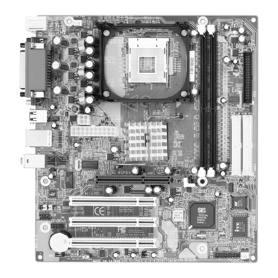
Page 14: Mainboard Layout
Installation Mainboard Layout Page 3-2... -
Page 15: Easy Installation Procedure
Installation Easy Installation Procedure The following must be completed before powering on your new system: 3-1. CPU Installation 3-2. Jumper Settings 3-3. System Memory Configuration 3-4. Expansion Slots 3-5. Device Connectors 3-1 CPU Installation <Figure 2> <Figure 1> Pin 1 Step 1 Step 2 Align pin 1 on the CPU with pin 1 on... - Page 16 Installation <Figure 3> <Figure 4> Step 3 Step 4 Close the socket by lowering and Apply thermal compound to the top of locking the actuation lever. the CPU and install the heatsink as shown. <Figure 5> <Figure 6> Step 5 Step 6 Install the cooling fan assembly.
-
Page 17: Jumper Settings
Installation 3-2 Jumper Settings JCMOS: Clear CMOS data Jumper If the CMOS data becomes corrupted or you forgot the supervisor or user password, clear the CMOS data to reconfigure the system back to the default values stored in the ROM BIOS. Settings: 1-2: Normal (Default) 2-3: Clear CMOS... -
Page 18: System Memory Configuration
Installation 3-3 System Memory Configuration The mainboard accommodates two PC2100/PC2700/PC3200 184-pin DIMMs (Dual In- line Memory Modules): • Supports up to 2.0GB of 266/333/400 MHz DDR SDRAM. • Supports up to 2 DDR DIMMs (refer to Table 1). • Supports unbuffered non-ECC DIMMs only. •... -
Page 19: Dimm Module Installation
Installation DIMM Module Installation Figure 8 displays the notch on the DDR DIMM memory module. DIMMs have 184 pins and one notch that matches with the DDR DIMM socket. DIMM modules are installed by placing the chip firmly into the socket and pressing straight down as shown in figure 9 until the white clips close and the module fits tightly into the DIMM socket (figure 10). -
Page 20: Expansion Slots
Installation 3-4 Expansion Slots AGP Slot The mainboard is equipped with an AGP slot. Make sure you install a card that supports the 1.5V specification. PCI Slots AGP Slot The mainboard is equipped with 3 PCI slots. PCI Slots Installing an Expansion Card The steps below assume that the mainboard is already installed in the system chassis. - Page 21 Installation AGP Card Installation Caution 1. AGP card component is blocked by DIMM socket lock. 2. AGP slot clicker is not locked. 3. AGP card edge connector is not inserted properly. 1. AGP card component is not blocked by DIMM socket lock. 2.
- Page 22 Installation 3-5 Connectors RJ-45 LAN Parallel Port (Optional) Line-in/Rear out (Light blue) PS/2 Mouse Line-out/Front out (Lime) PS/2 Mic-in/Center&Subwoofer (Pink) Keyboard COM1 VGA1 USB2.0 ports x 4 Figure 11 - I/O Ports JCPU_FAN / JSYS_FAN: JCPU_FAN CPU/Chassis Fan Power Connectors JCPU_FAN: The CPU must be kept cool by using a heatsink with fan assembly.
- Page 23 Installation Floppy Controller Connector This mainboard connects floppy disk drive. IDE1/IDE2:Ultra DMA-66/100/133 Primary/Secondary IDE2 IDE1 IDE Connector This mainboard is equipped with 2 IDE connectors to support up to 4 ATA-100 IDE drives. It supports PIO and DMA mode operations for maximum data transfer rate of 133MB/sec per channel.
- Page 24 Installation CFPA: Front Panel Audio Connector When the jumpers are removed this connector can be used for front panel audio. The front panel phone jack should have “normal close” switch. Without phone plug inserted, the rear panel audio is enabled. With phone plug inserted, the rear panel audio will be disabled.
- Page 25 Installation COM2: Serial Port Connector The serial port can be used with modems, serial printers, remote display terminals, and other serial device. Ground RXD DTR CUSB3: Two USB 2.0 ports USB2.0 allows data transfer speed up to 480Mbps. This mainboard includes 2 additional USB2.0 ports, identified by two 10-pin connector.
- Page 26 Installation CFP: Front Panel Connector HD_LED This LED will light up whenever the hard drive is being accessed. PWR_LED This connects to the power button of the system chassis This switch allows you to reboot without having to power off the system thus prolonging the life of the power supply or system.
-
Page 27: External Modem Ring-In Power On And Keyboard Power On Function (Kbpo)
Installation 3-6 External Modem Ring-in Power ON and Keyboard Power ON Functions (KBPO) Modem-Ring Power ON Function The I/O chipset provides the two serial ports with the External Modem Ring-in Power ON function. Once you connect an external modem to COM1 or COM2, the mainboard enables you to turn on the system through remote and host dial-up control. -
Page 28: Acpi S3 (Suspend To Ram) Function
Installation 3-7 ACPI S3 (Suspend To RAM) Function This mainboard supports the STR (Suspend To RAM) power management scheme by maintaining the appropriate power states in the DDR SDRAM interface signals. The power source to the DDR SDRAM is kept active during STR (ACPI S3). -
Page 29: Section
BIOS Section 4 BIOS SETUP Main Menu The ROM BIOS contains a built-in Setup program which allows user to modify the basic system configuration and hardware parameters. The modified data is stored in a battery-backed CMOS, so that data will be retained even when the power is turned off. -
Page 30: Standard Cmos Setup
BIOS The main menu displays all the major selection items. Select the item you need to reconfigure. The selection is made by moving the cursor (press any direction (arrow key ) to the item and pressing the ‘Enter’ key. An on-line help message is displayed at the bottom of the screen as the cursor is moved to various items which provides a better understanding of each function. -
Page 31: Advanced Bios Features
BIOS 4-2 Advanced BIOS Features Selecting the “ADVANCED BIOS FEATURES” option in the CMOS SETUP UTILITY menu allows users to change system related parameters in the displayed menu. This menu shows all of the manufacturer’s default values for the board. Pressing the [F1] key displays a help message for the selected item. - Page 32 BIOS Note: It is recommend to enable Hyper-Threading Technology on system with Windows XP and Linux 2.4 and disabling it for legacy OS. CPU L2 Cache ECC Checking This item allows you to enable/disable CPU L2 Cache ECC checking. Options: Enables, Disabled. Quick Power On Self Test This category speeds up the Power On Self Test (POST).
- Page 33 BIOS Typematic Rate Setting This determines the keystrokes repeat rate. The default is Disabled. Enabled: Allows typematic rate and typematic delay programming. Disabled: The typematic rate and typematic delay will be controlled by the keyboard controller in your system. Typematic Rate (Chars/Sec) This is the number of characters that will be repeated by a keyboard press.
-
Page 34: Advanced Chipset Features
BIOS HDD S.M.A.R.T. Capability The S.M.A.R.T. (Self-Monitoring, Analysis, and Reporting Technology) system is a diagnostics technology that monitors and predicts device performance. S.M.A.R.T. Software resides on both the disk drive and the host computer. If a device failure is predicted, the host software, through the Client WORKS S.M.A.R.T applet, warns the user of the impending condition and advises appropriate action to protect the data. - Page 35 BIOS Video RAM Cacheable This item allows the video RAM to be cached in memory for faster execution. Options: Disabled, Enabled. DRAM Clock / Timing Control Scroll to DRAM Clock/Timing Control and press <Enter>. The following screen appears: Performance Mode This item will enhance the memory performance.
- Page 36 BIOS RAS to CAS Delay (tRCD) This item sets the delay in clock cycles between RAS (Row Address Strobe) and CAS (Column Address Strobe) . Options: 2T ~ 5T. AGP&P2P Bridge Control Scroll to AGP&P2P Bridge Control and press <Enter>. The following screen appears: AGP Aperture Size (MB) This item defines the size of the aperture if you use an AGP graphics adapter.
-
Page 37: Integrated Peripherals
BIOS VGA Share Memory Size This item allows you to select the VGA share memory size for video. Options: 16MB, 32MB, 64MB, 128MB. Graphics Engin Clock This item allows you to select the Graphics Engine Clock. Options: 133MHz, 166MHz, 200MHz. 4-4 Integrated Peripherals Figure 5: Integrated Peripherals IDE HDD Block Mode... - Page 38 BIOS IDECH0 / IDECH1 Access Interface IDE Access Interface Selection. Options: EDB Bus, PCI Bus. USB0 / USB1 / USB2 / USB2.0 Access Interface USB Access Interface Selection. Options: EDB Bus, PCI Bus. MAC Access Interface MAC Access Interface Selection. Options: EDB Bus, PCI Bus.
-
Page 39: Onboard Device
BIOS to 4 provide successively increased performance. In Auto mode, the system automatically determines the best mode for each device. Options: Auto, Mode 0 ~ 4. Primary/Secondary Master/Slave UDMA Select the mode of operation for the IDE drive. Ultra DMA-100/133 implementa- tion is possible only if your IDE hard drive supports it and the operating environ- ment includes a DMA driver. - Page 40 BIOS USB Ports Number Selects the USB Ports number. Options: 3 Ports, 4 Ports, 5 Ports, 6 Ports . USB 2.0 Support Enables the USB2.0 Support. Options: Enabled, Disabled. USB Keyboard Support Enable/Disable support for USB keyboard under DOS. Options: Enabled, Disabled. USB Mouse Support Enable/Disable support for USB mouse under DOS.
- Page 41 BIOS Onboard Serial Port 1/2 Select an address and corresponding interrupt for the first and second serial ports. Options: 3F8/IRQ4, 2E8/IRQ3, 3E8/IRQ4, 2F8/IRQ3, Disabled, Auto. UART Mode Select This field configures the onboard CIR pin header for IR application. Select the required IR protocol or select “Normal”...
-
Page 42: Power Management Setup
BIOS 4-5 Power Management Setup Choose the “POWER MANAGEMENT SETUP” in the CMOS SETUP UTILITY to display the following screen. This menu allows the user to modify the power management parameters and IRQ signals. In general, these parameters should not be changed unless it’s absolutely necessary. - Page 43 BIOS Suspend Mode Automatically, shuts off all devices except the CPU after a preset period of system inactivity. Options: Disabled, 1 , 2, 4 ,6, 8, 10, 20, 30, 40 min and 1 hour . Video Off Option When enabled, this feature allows the VGA adapter to operate in a power saving mode. Always On: Monitor will remain on during power saving modes.
- Page 44 BIOS PwerOn After Pwr-Fail This item enables your computer to automatically restart or return to its last operat- ing status after power returns from a power failure. Off: The system stays off after a power failure. Former-Sts: The system returns to the state it was in just prior to the power failure.
- Page 45 BIOS PCIPME Power Up Control An input signal from PME on the PCI card awakens the system from a soft off state. Options: Enabled, Disabled. USB Port Wake Up Control When enabled, any USB Keyboard or mouse activity awakens the system from S3 mode.
-
Page 46: Pnp/Pci Configuration Setup
BIOS 4-6 PNP/PCI Configuration This page lets the user to modify the PCI IRQ signals when various PCI cards are inserted. WARNING: Conflicting IRQ’s may cause system unable to locate certain devices. Figure 7: PNP/PCI Configuration Setup Reset Configuration Data This setting allows you to clear ESCD data. - Page 47 BIOS PCI/VGA Palette Snoop This item is designed to overcome problems that may be caused by some nonstandard VGA cards. Options: Enabled, Disabled. Interrupt requests are shared as shown below: IMPORTANT! When using PCI cards on shared IRQ slots, make sure its drivers support “Shared IRQ”, or that the cards do not need IRQ assignments.
-
Page 48: Pc Health Status
BIOS 4-7 PC Health Status Figure 8: PC Health Status Show PC Health in POST When this function is enabled the PC Health information is displayed during the POST (Power On Self Test). Options: Enabled, Disabled. Shutdown Temperature This is the temperature that the computer will turn off the power to combat the effects of an overheating system (requires ACPI to be enabled in Power Manage- ment BIOS and ACPI compliant operating system). -
Page 49: Power Bios Features
BIOS System/CPU Temperature Displays the current system/CPU temperature. CPU/System FAN Displays the current speed of the CPU and chassis fan speed in RPMs. 4-8 POWER BIOS Features This page lets you adjust various parameters to obtain improved performance for overclocking. Warning: Overclocking requires expert knowledge and risks permanent damage to system components. - Page 50 BIOS CPU Clock Ratio Use this item to select a multiplier to set the CPU frequency. See CPU Clock/Speed below for explanation. Key in the DEC (decimal) number for the CPU Clock Ratio. Auto Detect DIMM/PCI Clk When enabled the mainboard automatically disables the clock source for a PCI slot which does not have a module in it, reducing EMI (ElectroMagnetic Interference).
-
Page 51: Defaults Menu
BIOS Note: Overclocking failure will cause no display on monitor. At this instant, press <Insert> key to revert back to the initial or default setting to boot up your system. CPU : DRAM Frequency Ratio This item allows you to select CPU and DRAM Frequency ratio. Options: SPD, 1:1, 3:4, 3:5, 1:2. -
Page 52: Set Password
BIOS 4-10 Set Password This function lets you set either Supervisor or User Password, or both, to prevent unauthorized changes to BIOS menus. supervisor password: full rights to enter and change options of the setup menus. user password: only enter but no rights to change options of the setup menus. -
Page 53: Exit Without Saving
BIOS 4-11 Exiting BIOS Save & Exit Setup Pressing <Enter> on this item asks for confirmation: Save to CMOS and EXIT (Y/N)? Y Pressing “Y” stores the selections made in the menus in CMOS – a special section of memory that stays on after you turn your system off. The next time you boot your computer, the BIOS configures your system according to the Setup selections stored in CMOS. - Page 54 BIOS Page 4-26...
-
Page 55: Driver Installation
Drivers Installation Section 5 DRIVER INSTALLATION Easy Driver Installation Insert the bundled CD-disk, the main menu screen will appear. The main menu displays buttons that link you to the supported drivers, utilities and software. Step 1 : Click “SIS AGP DRIVER” to install graphics driver. Step 2 : Click “AC’97 AUDIO DRIVER”... -
Page 56: Realtek Sound Manager Quick User Guide
Drivers Installation Realtek Sound Manager Quick User-guide Introduction To obtain the best performance from your audio system, run the "Sound Manager" utility to adjust the settings to suit your needs. This section of the manual is intended to provide a quick user-guide to setup "Sound Manager". For more detailed information, refer to "Sound Manager manual"... - Page 57 Drivers Installation Equalizer: <Figure 3> 3. There are 10 bands of equalizer control, check "ON" when you want to adjust the equalizer. Speaker Configuration: <Figure 4> 4. This page displays the mainboards's phone jack function when a corresponding audio mode (no. of speaker) is selected. Figure 4 above shows the phone jack setup for 2 channel mode.
- Page 58 Drivers Installation Speaker Configuration: <Figure 5> 5. For 6 channel mode, the audio combination is shown above. Speaker Test: <Figure 6> 6. To test the speaker , select the “Speaker Test” page and click directly on the speakers shown on the screen. Page 5-4...
- Page 59 Drivers Installation SPDIF-In: <Figure 7> 7. This page shows S/PDIF IN function on your system. a. Click "Auto Lock" to detect S/PDIF input and display its information. b. Check "Real-time S/PDIF-In monitor" to listen to the S/PDIF IN signal through Line-out connector. SPDIF-Out: <Figure 8>...
- Page 60 Drivers Installation This board is equipped with Jack Sensing capability. If an audio device is plugged into the wrong connector, a warning message will appear to remind users to check the connection. Connector Sensing: <Figure 9> 9. Push "Start" button to start the sensing. Please remember to terminate all audio applications before starting the sensing.
- Page 61 Drivers Installation Connector Sensing: <Figure 11> 11. After closing EZ-Connector, this page will show the latest connector status as above. General: <Figure 12> 12. This page displays information regarding the audio hardware and software. To remove "Sound Manager" icon from Windows Task bar, uncheck "Show icon in system tray".
- Page 62 Drivers Installation Page 5-8...
-
Page 63: Appendix
Appendix Appendix A Realtek Media Player User’s Guide Realtek Media Player Platform 06 - Reo Speedwagon 06-Reo Speedwagon - K 03:31 Functional Descriptions A. Playback Windows Display Playback windows displays the following mode information: 1. Playback Time Display 2. Voice Cancellation Mode Display 3. - Page 64 Appendix B. Playback Function Controls There are 8 selectable functions for the playback: 1. Volume control High/Low Adjustment Bar. 2. Pitch control 4-step High/Low Adjustment Bar. 3. Repeat mode Choice of Repeat, All Repeat, Random or No Repeat Mode. 4. Mute Mute On/Off Mode select.
- Page 65 Appendix D. Seeking bar Display Animated Playback Status E. Title/Play List Windows Display Currently Selected Title(s) F. Title/Play List Edit Controls There title/play list controls include “Add”, “Del”, “Clear”, “Load”, & “Store”. 1. Add Add to the Title/Play List. 2. Del Remove form the Title/Play List.
- Page 66 Appendix J. Platform Display Panel Controls The platform display panel control include “Minimize” & “Close”. 1. Minimize Minimize Platform Display Panel. 2. Close Close/Exit Platform Display Panel. K. Equalizer Control Panel The Equalizer Control Panel include “On/Off” & “Preset”. 1. On/Off Enable/Disable Equalizer.
-
Page 67: Update Your System Bios
Appendix Appendix B B-1 Update Your System BIOS Download the xxxxx.EXE file corresponding to your model from our website to an empty directory on your hard disk or floppy. Run the downloaded xxxxx.EXE file and it will self extract. Copy these extracted files to a bootable floppy disk. Note: The floppy disk should contain NO device drivers or other programs. - Page 68 Appendix 5. Key in File Name to save previous BIOS to file. XXXX XXXXX xxxxx.bin xxxxx.bin 6. To confirm and proceed, please key in [Y] to start the programming. XXXX XXXXX xxxxx.bin xxxxx.bin 7. The BIOS update is finished. XXXX XXXXX xxxxx.bin F10 : Exit...
-
Page 69: Eeprom Bios Remover
Appendix Appendix C EEPROM BIOS Remover Do not remove the BIOS chip, unless instructed by a technician and only with a PLCC IC extractor tool. The BIOS socket is fragile may be damaged if an improper method to replace the BIOS chip is applied. - Page 70 Appendix...
-
Page 71: Ghost 7 Quick User's Guide (Optional)
Appendix Appendix D D-1 GHOST 7 Quick User’s Guide (Optional) Installation is very easy. You only need to copy the Ghost7 folder or Ghost.exe to your hard disk. Main Menu Description of Menu Ghost clones and backs up Disk and Partition. In which Disk indicates hard disk options Partition indicates partition options Check indicates check options... - Page 72 Appendix There are 3 hard disk functions: 1. Disk To Disk (disk cloning) 2. Disk To Image (disk backup) 3. Disk From Image (restore backup) Important! 1. To use this function, the system must have at least 2 disks. Press the Tab key to move the cursor.
- Page 73 Appendix Disk To Image (Disk Backup) 1. Select the location of the Source drive. 2. Select the location for storing the backup file. 3. Click OK to display the following confirmation screen. Select Yes to start. Disk From Image (Restore Backup) 1.
- Page 74 Appendix 2. Select the Destination drive of the disk to be restored. 3. When restoring disk backup, set the required partition size as shown in the following figure. 4. Click OK to display the following confirmation screen. Select Yes to start. Partition...
- Page 75 Appendix There are 3 partition functions: 1. Partition To Partition (partition cloning) 2. Partition To Image (partition backup) 3. Partition From Image (restore partition) Partition To Partition (Partition Cloning) The basic unit for partition cloning is a “partition”. Refer to “disk cloning” for the operating method.
- Page 76 Appendix 4. Is the file compressed? There are 3 options: (1) No: do not compress data during backup (2) Fast: Small volume compression (3) High: high ratio compression. File can be compressed to its minimum, but requiring longer execution time. 5.
- Page 77 Appendix 3. Select the disk to be restored. 4. Select the partition to be restored. 5. Select Yes to start restoring. Check This function is to check possible error caused by defective FAT or track during backup or restoring.
- Page 78 Appendix How to Reinstall Windows in 2 Minutes This chapter guides you how to setup your computer properly and, if necessary, reinstall Windows in 2 minutes. Ghost provides different methods to complete this task. The following two sections explain how to create an emergency Recover Floppy and Recover CD: Emergency Recover Floppy Divide a hard disk into two partitions.
- Page 79 Appendix (2) After booting, the screen displays the Menu. Select Backup or Restore: Since the user may install other applications in the future, he/she may alter Autoexec.bat file to back up or restore the user-defined Image file as follows: B a c k u p B a c k u p B a c k u p B a c k u p...
- Page 80 Appendix Recover CD The following is a simple guide to create a recover CD: 1. First, create a recover floppy disk contains the following with any copy program such as “Easy CD Create” (Note 2) : Bootable files (Command.com and Io.sys and MSDOS.SYS) Config.sys (Configuration setup file) Autoexec.bat (Auto-execution batch file) Mscdex.exe (CD-Rom execution file)
Need help?
Do you have a question about the SiS 661FX and is the answer not in the manual?
Questions and answers