Table of Contents
Advertisement
Quick Links
SERVICE MANUAL
MP3
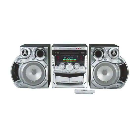
SP-MXGA77
Contents
Importance administering
point on the safety
STANDBY
STANDBY/ON
C O M P A C T
C O M P O N E N T
S Y S T E M
REC START
/ STOP
Cd REC
START
DUBBING
DISPLAY
PHONES
SOUND
TURBO
SUBWOOFER LEVEL
TUNING
TUNING
BEEP
EJECT
CA-MXGA77
1-2
Flow of functional operation
1-3
1-4
1-5
Trouble shooting
1-18
Description of major ICs
1-19
COPYRIGHT
2003 VICTOR COMPANY OF JAPAN, LTD.
CD
1
CD
2
CD
3
DISC CHANGE
M X - G A 7 7
REPEAT
PROGRAM
RANDOM
CLOCK
/ TIMER
PRESET
SET
CANCEL
/ DEMO
Tape A / B
EJECT
SP-MXGA77
until TOC read
Area suffix
J ------------------- U.S.A.
C ---------------- Canada
1-23
1-24
1-24
1-25
1-29~42
No.22001
May. 2003
Advertisement
Table of Contents

Related Manuals for JVC MX-GA77


Summary of Contents for JVC MX-GA77
- Page 1 MX-GA77 SERVICE MANUAL COMPACT COMPONENT SYSTEM MX-GA77 Area suffix J ------------------- U.S.A. C ---------------- Canada DISC CHANGE STANDBY STANDBY/ON C O M P A C T C O M P O N E N T S Y S T E M...
- Page 2 MX-GA77 1. This design of this product contains special hardware and many circuits and components specially for safety purposes. For continued protection, no changes should be made to the original design unless authorized in writing by the manufacturer. Replacement parts must be identical to those used in the original circuits. Services should be performed by qualified personnel only.
- Page 3 MX-GA77 Importance administering point on the safety 6.3A 125V 6.3A 125V 8A 125V 5A 125V RFS2 8A 125V Fuse board (Forward side) Power supply board (Forward side) Caution: For continued protection against risk of fire, replace only with same type 5A/125V for RFS2, 6.3A/125V for RFS5 and RFS6, 8A/125V for RFS7...
-
Page 4: Preventing Static Electricity
MX-GA77 Preventing static electricity 1. Grounding to prevent damage by static electricity Electrostatic discharge (ESD), which occurs when static electricity stored in the body, fabric, etc. is discharged, can destroy the laser diode in the traverse unit (optical pickup). Take care to prevent this when performing repairs. -
Page 5: Disassembly Method
MX-GA77 Metal cover Disassembly method Removing the metal cover (See Fig.1) Remove the three screws A attaching the metal cover on the back of the body. Remove the six screws B attaching the metal cover on both sides of the body. - Page 6 MX-GA77 CW105 CD board Rear panel CD changer unit CW104 Fig.6 Front panel assembly CD changer unit (both sides) Main board Fig.5 Rear panel Fig.7 Front panel Main board assembly CW101 Removing the front panel assembly CW109 (See Fig.8 to 10)
- Page 7 MX-GA77 Removing the heat sink & amp. board Joint2 (Bottom side) (See Fig.8, 11 and 12) Prior to performing the following procedure, remove the metal cover and CD changer unit. Disconnect the card wire from the connector ACW1 and the harness from the connector ACW2 on the amp.
- Page 8 MX-GA77 CW101 Removing the main board (See Fig. 14) CW109 Prior to performing the following procedure, remove CW110 the metal cover, CD changer unit and rear panel. Main board CW108 Disconnect the card wire from the connector CW101 Fuse board and the harness from the connector CW108, CW109 and CW110 on the main board.
- Page 9 MX-GA77 Front panel assembly (inner side) <Front panel assembly> CD switch board Prior to performing the following procedure, remove the front panel assembly. Removing the CD switch board (See Fig.1) UCW03 Disconnect the card wire from the connector UCW03 on the CD switch board.
- Page 10 MX-GA77 CD changer uint (reverse side) <CD changer unit> Prior to performing the following procedure, remove CD tray the CD changer unit. Removing the CD tray (See Fig.1 and 2) CD board Loading pulley Turn the black loading pulley gear on the under side...
- Page 11 MX-GA77 Removing the sensor board (See Fig.5) CD tray (reverse side) Prior to performing the following procedure, remove the CD tray. Remove the screw A attaching the sensor board on the CD tray. Remove the sensor board releasing the two tabs a.
- Page 12 MX-GA77 Removing the belt, the CD board and the switch board (See Fig.8 and 9) Belt Prior to performing the following procedure, remove the CD tray. Detach the belt from the pulley on the upper side of the CD changer unit (Do not stain the belt with grease).
- Page 13 MX-GA77 Removing the CD mechanism holder assembly (mechanism included) Motor connecter (See Fig.10 to 13) Disconnect the harness from connector on the CD mechanism board in the CD mechanism assembly on the under side of the CD changer unit. Disconnect the card wire from the pickup unit connector.
- Page 14 MX-GA77 <CD mechanism section> Shutter Shaft Pickup unit Removing the CD mechanism holder from the CD • chager unit. (Refer to "Removing the CD mechanism holder assembly" ) Removing the pickup unit See Fig.1) 1. Removing the cut washer on the feed gear sleeve and pull out the feed gear.
- Page 15 MX-GA77 <Cassette mechanism section> R/P Head Prior to performing the following procedure, remove cassette mechanism assembly. Removing the R/P head. (See Fig.1 and 2) Remove the screw A on the right side of the R/P head. Remove the screw B on the left side of the R/P Pinch roller head.
- Page 16 MX-GA77 Removing the motor (See Fig. 4 to 6) Slide the plastic cover in the direction of the arrow, Plastic cover and remove the three claws. Then remove the plastic cover. Remove the two screws D fixing the motor. Be careful to grease's splash when the drive belt comes off.
- Page 17 MX-GA77 < Speaker section > It is exchange in a unit. Please do not decompose as much as possible. Removing the side panel (See Fig. 1) Remove the five screws A attaching the side panel and remove the side panel.
-
Page 18: Wiring Connection
MX-GA77 Wiring connection Color codes are shown below. Brown Orange Yellow Green Blue Violet Gray White Black 1-18... -
Page 19: Adjustment Method
MX-GA77 Adjustment method 1. Tuner * Adjustment Location of Tuner PCB AM(MW) RF AM(MW) OSC ITEAM Adjustment Adjustment Received FREQ. 600 KHz 530~1710 KHz Adjustment point Maximum Output 1~7.0 0.5V Output(Fig.1) MAIN TESTER Fig.1 OSC Voltage 1-19... - Page 20 MX-GA77 FM THD Adjustment SSG FREQ. 98 MHz Adjustment Output Antenna point FM DETECTOR COIL Terminal (FM DET) Oscilloscope FM S.S.G Input 60 dB Output Speaker Minumum Distortion (0.4% below) Terminal Input output (Fig.2) Distortion Meter Fig.2 IF CENTER and THD Adjustment FM Search Level Adjustment SSG FREQ.
- Page 21 MX-GA77 2. Cassette Deck To adjust tape speed Notes Cassette Deck Frequency Counter 1) Measuring tape: i) VT-712/MTT-111(or equivalent) (Tapes recorded with 3kHz) SPK OUT ii) AC-225/MTT-5512(or equivalent) output Fig.1 2) Connect the cassette deck to the frequency counter as in fig.1.
- Page 22 MX-GA77 2. Adjust Deck 2 Play Level/REC BIAS Pre-Setup Step Item Pre-Setup To Adjust Standard Remark Condition After putting VT-703 AZIMUTH SPK OUT Turn the control Max output After into Deck 2 (VTVM is screw to as and same phase...
-
Page 23: Flow Of Functional Operation Until Toc Read
MX-GA77 Flow of functional operation until TOC read Check Point Play Key Power ON RESET a CD LSI Confirm that the voltage at the pin17 of KB9226(IC101) is "L" "H". Confirm that the voltage at the pin33 LIMIT SW ON of KB9226(IC101) is "H"... -
Page 24: Maintenance Of Laser Pickup
MX-GA77 Maintenance of laser pickup (1) Cleaning the pick up lens (2) Life of the laser diode Before you replace the pick up, please try to When the life of the laser diode has expired, clean the lens with a alcohol soaked cotton the following symptoms will appear. -
Page 25: Troubleshooting
MX-GA77 Troubleshooting 1. Amplifier Power malfunction No output 1-25... - Page 26 MX-GA77 2.Tuner malfunction (FM/AM) 3.Tape 1-26...
- Page 27 MX-GA77 4.CD 1-27...
- Page 28 MX-GA77 5.CD - MP3 parts 1-28...
- Page 29 MX-GA77 Description of major ICs LC876764 (UIC1) : Microcontroller 1.Pin layout S48/PG0 S19/PC3 S49/PG1 S18/PC2 S17/PC1 S50/PG2 S16/PC0 S51/PG3 VDD3 S15/T15 S14/T14 S13/T13 VSS2 S12/T12 S11/T11 VDD2 S10/T10 S9/T9 S8/T8 S7/T7 S6/T6 P10/SO0 P11/SI0/SB0 S5/T5 S4/T4 P12/SCK0 S3/T3 P13/SO1 S2/T2...
- Page 30 MX-GA77 3. Pin function (1/2) Pin name Function VSS1, 2 Power supply (-) VDD1,2,3,4 Power supply (+) FIX0 Test pin Set as VSS with the user’s option. (see Note 1) PORT0 • 8bit input/output port P00 to P07 • Data direction programmable in nibble units •...
- Page 31 MX-GA77 3. Pin function (2/2) Pin name Function S32 to S39 • Output for VFD display controller segment • Other functions High voltage input port: PE0 to PE7 S40 to S47 • Output for VFD display controller segment • Other functions:...
- Page 32 MX-GA77 KB9226 (IC101) : RF amp. & servo signal processor 1. Pin layout PDAC PDBD LOCK WDCK S1L9226X CLVI RESET DCCI DCCO MDATA VREF ISTAT 2. Block diagram Center Tracking Error RF & Focus RF AGC & EQ Voltage (RW)
- Page 33 MX-GA77 3. Pin function Pin No. Symbol Function RF summing amp. inverting input RF summing amp. output RFO DC eliminating input(use by MIRROR, FOK ,AGC & EQ terminal) RF equalizer output EFMI EFM slice input. (input impedance 47K) Main power supply...
- Page 34 MX-GA77 5L9290 (IC201) : Digital signal processor for CDP 1. Pin layout VSSA_PLL BCKO VCO1LF LRCKO VSSD_PLL SADTO VDDD_PLL DATX VDDD1_5V C2PO S5L9290X JITB DSP+DAC XOUT SBCK 48-LQFP-0707 VSSD1_5V VDDD3-5V EFMI VSSD2-3V LOCK VDDD2-3V SMEF MUTE SMON SQDT 2. Block diagram...
- Page 35 MX-GA77 3. Pin function Symbol Function VSSA_PLL Analog Ground for DPLL VCO1LF Pump out for VCO1 VSSD_PLL Digital Ground Separated Bulk Bias for DPLL VDDD_PLL Digital Power Separated Bulk Bias for DPLL (3V Power) VDDD1-5V Digital Power (5V Power, I/O PAD) X'tal oscillator input (16.9344MHz)
- Page 36 MX-GA77 HA12237 (JIC01) : Audio signal processor 1. Block diagram REC OUT(L) REC OUT(R) ALC(L) ALC(R) REC IN(L) REC IN(R) PB OUT(L) PB OUT(R) TAI(L) TAI(R) EQOUT(L) EQOUT(R) PB-EQ(L) PB-EQ(R) PB-NF2(L) PB-NF2(R) 2. Pin function Pin No. Symbol Function Pin No.
- Page 37 MX-GA77 KS9274 (IC601) : CD-MP3 decoder 1.Block diagram CD-ROM Decoder MP3 Decoder INTERFACE 20-22 24-27 DRAM CONTROLLER HOST MCU INTERFACE 44-63 35-39 1M 4bits DRAM HOST MCU 2.Pin function System clock input RESETB System reset actibe LOW FILTER_0 820uF to GND940uF to GND FILTER_1 When "HIGH"...
- Page 38 MX-GA77 TDA7442D (EIC01) : Audio processor 1.Pin layout R_IN3 R_IN4 R_IN2 LOUT R_IN1 ROUT L_IN1 AGND L_IN2 L_IN3 CREF L_IN4 MUXOUTL IN(L) DIG-GND MUXOUT(R) TREBLE(R) IN(R) TREBLE(L) BIN(R) BOUT(R) BIN(L) BOUT(L) 2.Block diagram 5.6K 5.6nF 100nF 100nF 100nF 2.2 F...
- Page 39 MX-GA77 L4959 (PIC02) : Voltage regulator 1.Pin layout OUT 12V(a) OUT 8.6V EN 8.6V EN 12V(a) EN 12V(b) N.C. OUT 5.6V OUT 12V(b) TAB CONNECTED TO PIN 6 D97AU716A 2.Block diagram 2/10 5.6V, 250mA OUT 5.6V REGULATOR 8.6V, 600mA OUT 8.6V...
- Page 40 MX-GA77 M11L1644 (IC602) : DRAM 1. Block diagram CONTROL DATA-IN BUFFER LOGIC I/O0 I/O3 CLOCK GENERATOR DATA-OUT BUFFER COLUMN COLUMN ADDRESS DECODER BUFFER 2048 REFRESH SENSE AMPLIFIERS CONTROLLER I/O RATING REFRESH 2048 x 4 COUNTER 2048 x 2048 x 4...
- Page 41 MX-GA77 STK403-070 (FIC01) : Power amp. 1.Pin layout +Vcc -Vcc +TRE ST-BY 2.Block diagram Pre Driver IC Pre Driver IC Bias Circuit STK412-020 (WIC01) : Power amp. TR41 1.Block diagram 1817 Comaprator TR11 TR12 TR16 TR19 TR14 TR13 TR18 TR10...
- Page 42 MX-GA77 PT8300 (UIC03, UIC04) : DRAM 1.Pin layout /RESET PULLUP LATCH LATCH0 CLK0 2.Block diagram PULLUP P2 P3 P10 P11 P12 P13 P14 O7 O8 LATCH LATCH LATCH 16-BIT I7 I8 RESET SHIFT REGISTER1: 16-BIT SHIFT REGISTER SERIAL TO PARALLEL...
- Page 43 MX-GA77 < M E M O > 1-43...
- Page 44 MX-GA77 VICTOR COMPANY OF JAPAN, LIMITED AV & MULTMEDIA COMPANY AUDIO/VIDEO SYSTEM CATEGORY 10-1,1 chome,Ohwatari-machi,maebashi-city,371-8543,Japan Printed in Japan (No.22001) 200305...
- Page 45 MX-GA77 SCHEMATIC DIAGRAMS COMPACT COMPONENT SYSTEM MX-GA77 Area suffix CD-ROM No.SML200305 J ------------------- U.S.A. C ---------------- Canada DISC CHANGE STANDBY STANDBY/ON C O M P A C T C O M P O N E N T S Y S T E M...
- Page 46 MX-GA77 In regard with component parts appearing on the silk-screen printed side (parts side) of the PWB diagrams, the parts that are printed over with black such as the resistor ( diode ( ) and ICP ( ) or identified by the " " mark nearby are critical for safety.
-
Page 47: Block Diagram
MA-GA77 Block diagram... -
Page 48: Main Section
Standard schematic diagrams Main section To UCW01 Sheet 2/5 To CON01 KTC8050 Sheet 5/5 KTC8050 KTC8050 To CW106 Sheet 4/5 KTC8050 SHEET CIRCUIT DESCRIPTION NUMBER Main FL display & System control Amp. MAIN signal TUNER signal CD signal Tuner MX-GA77 JUS MAIN... - Page 49 MA-GA77 To ACW1 Sheet 3/5 To ACW2 Sheet 3/5 Parts are safety assurance parts. gnal TAPE P.B. signal When replacing those parts, make sure to use the specified parts. TAPE REC. signal SHEET 1/5...
- Page 50 MX-GA77 FL display & System control section UCW03 To CW101 Sheet 1/5 UCW05 MX-GA77 fornt...
- Page 51 MA-GA77 To CW105 Sheet 4/5 UCW04 UCW02 SHEET 2/5...
- Page 52 MX-GA77 Amp. section To CW106 Sheet 1/5 To CW105 Sheet 1/5 MX-GA77 JUS amp.
- Page 53 MA-GA77 Parts are safety assurance parts. When replacing those parts, make MAIN signal sure to use the specified parts. SHEET 3/5...
- Page 54 MX-GA77 CD section To CW2 Sensor board Switc...
- Page 55 MA-GA77 To CW104 SHEET 1/5 To CW3 CD signal To UCW04 Switch board SHEET 2/5 SHEET 4/5...
- Page 56 MX-GA77 Tuner section To CW103 SHEET 1/5 2-10...
- Page 57 MA-GA77 FM/ TUNER signal AM signal SHEET 5/5 2-11...
-
Page 58: Printed Circuit Boards
MX-GA77 Printed circuit boards Main board 2-12... - Page 59 MA-GA77 Main board 2-13...
- Page 60 MX-GA77 Front board CD switch boa Front board 2-14...
- Page 61 MA-GA77 h board oard 2-15...
- Page 62 MX-GA77 Amp. board 2-16...
- Page 63 MA-GA77 2-17...
- Page 64 MX-GA77 CD servo board 2-18...
- Page 65 MA-GA77 Power supply board Trans. board Fuse board 2-19...
- Page 66 MX-GA77 VICTOR COMPANY OF JAPAN, LIMITED AV & MULTMEDIA COMPANY AUDIO/VIDEO SYSTEM CATEGORY 10-1,1 chome,Ohwatari-machi,maebashi-city,371-8543,Japan Printed in Japan No.22001SCH 200305...
-
Page 67: Parts List
MX-GA77 PARTS LIST [ MX-GA77 ] * All printed circuit boards and its assemblies are not available as service parts. Area suffix J ----------------------------- U.S.A. C -------------------------- Canada - Contents - 3- 2 Exploded view of general assembly and parts list (Block No.M1) 3- 6 Exploded view of general assembly and parts list (Block No.M2) -
Page 68: Exploded View Of General Assembly And Parts List
MX-GA77 Exploded view of general assembly and parts list Block No. Main board CD changer mechanism Phone jack CD switch board board 24-1 24-2 24-3 B x2 F x2 37 x2 38 x2 G x2 Cassette mechanism... - Page 69 MX-GA77 Main board Amp. board Phone jack board Tuner board RFS5 RFS6 RFS7 RFS8 25-1 Trans. board Fuse board 25-2 RFS2 25-3 Cassette mechanism...
- Page 70 MX-GA77 Parts list (General assembly) Block No. M1MM Item Parts number Parts name Q'ty Description Area AH64-01106G SCREW 4 M3X10 SILVER SCREW 3 FH M3X10 BLK 6002-000126 6003-000276 SCREW 40 BH M3X10 YEL 6003-000275 SCREW 24 BH M3X10 BLACK AH60-10107A...
- Page 71 MX-GA77 Parts list (General assembly) Block No. M1MM Item Parts number Parts name Q'ty Description Area AH61-01262A H SINK BRAKET AH64-02273D REAR CABINET AH62-00042A HEAT SINK 1 4959 AH61-40014A SUPPORT RIVET AH95-50001A LATCH ASSY DAMPER ASSY AH61-80030A AH61-00552A DOOR SPRING A...
-
Page 72: Speaker Box
MX-GA77 Exploded view of general assembly and parts list Block No. SPEAKER BOX Parts list (General assembly) Block No. M2MM Item Parts number Parts name Q'ty Description Area AH81-00959E SIDE PANEL 1 RIGHT AH81-00959F SIDE PANEL 1 LEFT AH81-01121A SCREW 5 4.0X40MM BK... -
Page 73: Cd Changer Mechanism Assembly And Parts List
MX-GA77 CD changer mechanism assembly and parts list Block No. Base main Tray stopper CD sub board... - Page 74 MX-GA77 Parts list (CD changer mechanism) Block No. MAMM Item Description Parts number Parts name Q'ty Area AH66-80022A SLIDE CAM 1 ABS HF-380 NTR AH66-60034A BELT LOAD 1 CR GEAR PULLEY 1 POM (M90-44)WHT AH66-20186A AH66-20187A GEAR-LOAD 1 POM (M90-44)BLK...
-
Page 75: Cassette Mechanism Assembly And Parts List
MX-GA77 Cassette mechanism assembly and parts list Block No. CWM43FF09 Note: Parts listed on the Parts List below can be supplied. However, parts that are not listed below cannot be supplied individually but only by purchasing the whole Cassette Mechanism Assembly Unit. (When ordering, use the Parts No. - Page 76 MX-GA77 Parts list (Cassette mechanism) Block No. MPMM Item Description Parts number Parts name Q'ty Area AH81-00472A PB HEAD 2 TC881CB067P AH81-00472B E HEAD 1 TC2131 PINCH ROLLER 2 22-027-41054 AH81-00472N AH81-00902E MOTOR ASSY 1 50-093-4879 AH81-00902G BF BELT 1 02-083-4236...
- Page 77 MX-GA77 Electrical parts list (Main board) Block No. 01 Item Parts number Parts name Remarks Area Item Parts number Parts name Remarks Area AC101 2301-000216 M.CAPACITOR 220NF 5% 50V AR119 2001-000281 CARBON RESISTOR 100 5% 1/8W AC102 2301-000474 M.CAPACITOR 8.2NF 10% 50V...
- Page 78 MX-GA77 Electrical parts list (Main board) Block No. 01 Item Parts number Parts name Remarks Area Item Parts number Parts name Remarks Area EC07R 2301-000454 M.CAPACITOR 5.6NF 10% 50V ER109 2001-000290 CARBON RESISTOR 10K 5% 1/8W EC08L 2301-000216 M.CAPACITOR 220NF 5% 50V...
- Page 79 MX-GA77 Electrical parts list (Main board) Block No. 01 Item Parts number Parts name Remarks Area JC105 2202-000781 C.CAPACITOR 100PF 10% 50V PD204 0402-000127 DIODE 1N4002 100V 1A JC106 2202-000781 C.CAPACITOR 100PF 10% 50V PD205 0401-000101 DIODE 1N4148 100V JC107 2202-000781 C.CAPACITOR...
- Page 80 MX-GA77 Electrical parts list (Front board) Block No. 02 Item Parts number Parts name Remarks Area Item Parts number Parts name Remarks Area BUZZ1 3002-001134 BUZZER 85DB 12V FR203 2001-000034 CARBON RESISTOR 220 5% 1/4W CW01B AH39-00247A LEAD CONNECTOR FR204...
- Page 81 MX-GA77 Electrical parts list (Front board) Block No. 02 Item Parts number Parts name Remarks Area Item Parts number Parts name Remarks Area FR266 2001-000034 CARBON RESISTOR 220 5% 1/4W FR329 0501-000422 TRANSISTOR KTA1273 FR267 2001-000034 CARBON RESISTOR 220 5% 1/4W...
- Page 82 MX-GA77 Block No. 02 Electrical parts list (Front board) Item Remarks Parts number Parts name Area UIC02 AC59-60060A MODULE REMOCON GP1U281R SHARP UIC03 0904-001621 PT8300 28P UIC04 0904-001621 PT8300 28P UX101 2801-001394 CRYSTAL 32.768KHZ 20PPM AH07-00098A VF DISPLAY BJ904GNK ZD101...
- Page 83 MX-GA77 Electrical parts list (Amp. board) Block No. 03 Item Parts number Parts name Remarks Area Item Parts number Parts name Remarks Area ACW1 3708-001167 CONNECTOR 14P 1.25MM ST AR10L 2001-000591 CARBON RESISTOR 3.3K 5% 1/8W ACW2 3711-003113 CONNECTOR 9P 1R 2.5MM ST...
- Page 84 MX-GA77 Electrical parts list (Amp. board) Block No. 03 Item Parts number Parts name Remarks Area FIC01 1201-001955 STK403-070 14P FIC02 1201-000191 BA4558 8P HRFS2 3602-000147 FUSE-CLIP HRFS5 3602-000147 FUSE-CLIP HRFS6 3602-000147 FUSE-CLIP HRFS7 3602-000147 FUSE-CLIP HRFS8 3602-000147 FUSE-CLIP AH41-00554A PCB-AMP 247 163 1.6T...
- Page 85 MX-GA77 Electrical parts list (CD board) Block No. 04 Item Parts number Parts name Remarks Area Item Parts number Parts name Remarks Area CW101 3708-001252 CONNECTOR 16P 1MM ST C402 2203-000260 CHIP CAPACITOR 10NF 10% 50V CW102 AH39-20561P LEAD CONNECTOR...
- Page 86 MX-GA77 Block No. 04 Electrical parts list (CD board) Item Parts number Parts name Remarks Area R128 2007-000653 CHIP RESISTOR 27K 5% 1/10W R129 2007-000941 CHIP RESISTOR 47K 5% 1/10W R132 2007-000300 CHIP RESISTOR 10K 5% 1/10W R133 2007-000300 CHIP RESISTOR...
- Page 87 MX-GA77 < M E M O > 3-21...
-
Page 88: Packing Materials And Accessories Parts List
MX-GA77 Packing materials and accessories parts list Block No. Block No. REMOCON ASSY 3-22... - Page 89 MX-GA77 Parts list (Packing) Block No. M3MM Item Parts number Parts name Q'ty Description Area AH69-00906B MASTER CARTON AH69-00906C MASTER CARTON AH69-00867B CUSHION L 1 FRONT AH69-00868B CUSHION R 1 REAR PORY BAG 1 SET AH69-30012T AH69-00525A PORY BAG 1 INSTRUCTIONS...