
Related Manuals for Takagi T-K3


Summary of Contents for Takagi T-K3
- Page 1 CONFIDENTIAL T-K3 Servi c e Manual Ver. 1.05 T-K3 Instantaneous Water Heater Service Manual TAKAGI Industrial Co. USA Inc. 5 Whatney Irvine, CA 92618 Toll Free: (888) 882-5244 USA Toll Free: (877) 877-4953 CANADA...
-
Page 2: Table Of Contents
CONFIDENTIAL T-K3 Servi c e Manual Ver. 1.05 Table of Contents 1. Specifications of the T-K3, T-K3-OS, and T-K3-SP……………..………………………… 3 2. Exterior view ……………………...…….…………………………………………………….. 4 3. Interior view …………………………….…………………………………………………….. 4. List of main components in the interior view …….………………………………………… 6 5. -
Page 3: Specifications Of The T-K3, T-K3-Os, And T-K3-Sp
CONFIDENTIAL T-K3 Servi c e Manual Ver. 1.05 1. Specifications of the T-K3, T-K3-OS, and T-K3-SP Model T-K3 T-K3-OS T-K3-SP Dimensions H20.5"×W13.8"×D8.5" H20.5"×W13.8"×D8.5" H20.5"×W13.8"×D8.5" Weight 40lbs. 199,000 190,000 INPUT BTU/h 11,000 Combustion Pow er vent System Indoor, Outdoor, Installation Outdoor Indoor &... -
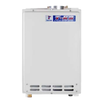
Page 4: Exterior View
CONFIDENTIAL T-K3 Servi c e Manual Ver. 1.05 2. Exterior view Front view 1 3 - 3 / 4 " ( 3 5 0 m m ) Side view 1 0 " ( 2 5 4 m m ) 4 - 1 / 2 " ( 1 1 4 . 2 m m ) 1 - 3 / 4 "... -
Page 5: Interior View
CONFIDENTIAL T-K3 Servi c e Manual Ver. 1.05 3. Interior view 4. List of main components in the interior view T-K3 Takagi Common parts Description Part# Part # For other units Case assembly EKK1D Combustion chamber EKK1Y Gas valve w ith Proportional... -
Page 6: List Of Main Components In The Interior View
CONFIDENTIAL T-K3 Servi c e Manual Ver. 1.05 4. List of main components in the internal view (cont’d) T-K3 Takagi Common parts Description Part# Part # with other models Transformer EKH09 TH1, OS, SP Water inlet EKK1U OS, SP Water outlet... -
Page 7: Schematic Diagram
T he rm is to r pl ug f il te r When a hot w ater tap is opened, cold w ater enters the T-K3 w ater heater. The w ater flow sensor detects this w ater flow and sends this information to computer. -
Page 8: Wiring Diagram
CONFIDENTIAL T-K3 Servi c e Manual Ver. 1.05 6. Wiring diagram AC120V White Blue Trans- Green former Ground Black Yellow Purple Orange Light blue Brown Ground G FI Heater Pr opor- ti onal Heater V alve Freeze protection Flow thermostat... -
Page 9: Wiring Diagram Checkpoints For Diagnosis
CONFIDENTIAL T-K3 Servi c e Manual Ver. 1.05 7. Wiring diagram check points for diagnosis Check- Part and Description Color of wires Normal range point Brown – Brown (A1) A, A1 100V Power supply AC 90~110V White – Black (A) -
Page 10: Resistance Values Of The Temperature Thermistors
CONFIDENTIAL T-K3 Servi c e Manual Ver. 1.05 8. Resistance values of the temperature thermistors Resistance values at different temperatures ºF T em perature ºC R esistance kΩ 23.76 19.08 15.43 12.56 10.28 8.47 7.02 5.85 4.90 4.12 T em perature ºF... -
Page 11: Operational Flow Chart
CONFIDENTIAL T-K3 Servi c e Manual Ver. 1.05 9. Operational flow chart Power supply ON Opeartion SW ON Remove cause FAV ; Flow Adjustment Valve B V ; Bypass Valve Opeartion lamp OFF F M ; Fan Motor OPEN FAV BV OHCF;... -
Page 12: Component Specifications
CONFIDENTIAL T-K3 Servi c e Manual Ver. 1.05 10. Component specifications 1. Burners 2. Manifold 3. Fan motor P.13 P.14 P.15 5. Flame rod 6. AFR rod Gas valve assembly F l a m e r o d F l a m e r o d P.16... - Page 13 Takagi Part # EKK1N Checkpoint There are 2 types of burners in the T-K3: the gas-rich burner stabilizes the flames within the combus tion chamber and the air-rich burner produces more heat in the Function combustion chamber. The burners facilitate the air/gas mixture necessary to produce the proper heat during the combustion reaction.
-
Page 14: Gas Manifold
CONFIDENTIAL T-K3 Servi c e Manual Ver. 1.05 10-2. Gas manifold T-K3 Part # #103 Takagi Part # EKK1F Checkpoint 1. The manifold distributes gas from the gas valves to the burners. The manifold has two types of the nozzles: one type for gas-rich burners (16 nozzles) and the... -
Page 15: Fan Motor
2. Unexpected working caused by the connectors of the fan motor getting wet. 3. Drops out from the bottom of the combustion chamber 1. T-K3 does not function properly Effects on the T-K3 2. Failure to ignite or abnormal ignition if fan motor fails 3. -
Page 16: Gas Valve Assembly
#105 Takagi Part # EKK1W Checkpoint Opens and closes the gas pathways of the T-K3 (main and solenoid gas valves) Function Modulates the gas flow from the gas inlet (proportional gas valve) 1. Gas leak from the valves. Failure events 2. -
Page 17: Flame Rod
1. The T-K3 stops operating. The "111" and/or "121" error code(s) will display Effects on the T-K3 if flame rod fails 2. The T-K3 will not initiate the ignition proc ess. The "721" error code will display Error codes when the flame rod fails. -
Page 18: Afr Rod
2. Detecting a false flame when no flames actually occur 1. The T-K3 stops operating. The "111" and/or "121" error code(s) will display 2. The T-K3 will not initiate the ignition process. The "721" error code will display Effects on the T-K3 3. -
Page 19: Heat Exchanger
Effects on the T-K3 2. Exhaust gas leakage (if this occurs, an overheat cutoff fuse is in place to if the heat detect this event and immediately stop the T-K3 from operating) exchanger fails . 3. Abnormal sounds during combustion Error co des when the heat excha nger fails. -
Page 20: Flow Adjustment Valve
1. Water leakage from valve. Failure event 2. The valve cannot modulate or make open/close positions. Effects on the T-K3 1. Water leakage from failed valve can damage other T-K3 components. if flow adjustment 2. Temperature fluctuations in the hot water output. valve 3. -
Page 21: Flow Sensor
Detects and measures water flow rate using a spinning impeller and magnetic pick-u Unable to detect or measure any water flow rate. Failure event Effects on the T-K3 Ignition sequence does not start (T-K3 will not initiate any operation) if flow sensor fails Error codes when 441 (only within multi-unit Easy-Link systems) the flow sensor fails. -
Page 22: Bypass Valve
Failure event 2. The valve cannot modulate or mak e open/close positions. Effects on the T-K3 1. Water leakage from failed valve can damage other T-K3 components if the bypass valve 2. Temperature fluctuations in the hot water output. fails Error codes when bypass valve fails. - Page 23 Failure event If the thermistors fail open or short, error code appears before starting operation. If Effects on the T-K3 resistance values are just off, T-K3 will have temperature fluctuations in hot water. if thermistor fails Error codes when 311 (Outlet)
- Page 24 2. Continuous detection of excessively high water temperatures (regardless of what the actual water temperature is) if switch fails "open". 1. Unable to shut down the T-K3 if the water temperature from the heat exchanger exceeds 194˚F (90˚C). Effects on the T-K3 Note: The mixing and outlet thermistors always act as backup hi-limit detectors to detect if hi-limit switch fails.
-
Page 25: Overheat Cutoff Fuse
Function exchanger and c ombustion chamber. Upon detection, communication between the computer board and gas valves will sever, shutting down the T-K3 instantly. The "111" or "121" error code will display. 1. Unable to detect the excessively high temperatures within the T-K3. -
Page 26: Freeze Protection Heaters
White - White wires The T-K3 has two types of the heaters in it. The one is for protecting of the heat exchanger and the outlet pipe, the other one is for protecting of the inlet pipe. For the outlet pipe... -
Page 27: Computer Board
Controls the functions of most of the parts in the T-K3. Function Malfunctioning computer Failure event -A component(s) may not operate within the T-K3. In most cases of computer Effects on the T-K3 if the computer board failure, the whole T-K3 does not operate at all. - Page 28 -To transform input voltage from 120VAC to 100VAC. Function -Every electrical component of the T-K3 is designed to only work with a 100VAC power supply, therefore, the T-K3 comes equipped with this transformer. 1. There is no power coming from the transformer.
- Page 29 2. OFF-failure: Always in the OFF mode (always stays tripped). 1. ON-failure: GFI cannot detect electrical leak age within the T-K3. Effects on the T-K3 2. OFF-failure: the T-K3 does not receive any power from the GFI, which if the GFI fails. means the T-K3 cannot operate.
- Page 30 #704 Takagi Part # EKN74 Checkpoint -To ignite the gas/air mixtures when the T-K3 is ready to burn gas on its burner surface. Function -The output voltage of the igniter is more than 14kV. 1. Unable to ignite during the ignition process.
-
Page 31: Freeze Protection Thermostat
Temperature detecting device whic h prevents the pipes within the T-K3 from Function freezing. When this device detects temperatures below 36.5˚F (2.5˚C) inside the T-K3, power is supplied to the electric heaters to prevent the T-K3 from freezing. 1. ON-failure (Always senses freezing temperatures, regardless of actual temperature). -
Page 32: Fault Analysis & Specifications
11. Fault Analysis & Specifications Remarks: 1 Proper range of values of voltage & resistance shown below. 2 Please refer to the wiring diagram for checkpoint positions. 3 Remove power to T-K3 when checking for continuity, disconnections, resistance value Nature of Fault Diagnosis Checkpoint ・... - Page 33 T-K3 Servi c e Manual Ver. 1.05 Nature of Fault Diagnosis Checkpoint Check whether the flow rate enough to keep the T-K3 ・ The hot water turns running. cold and stays cold Check if there is a recirculation system installed and check also if the recirc ulation line has enough check valves.
- Page 34 Checkpoint 1 Check if there is any blockage in the air inlet of the unit. 2 Check if there is any blockage along the exhaust run. 3 Check the manifold pressure in the T-K3. Error Code Malfunction description Cancellation method...
- Page 35 ① shown after Check the connection of ground wire; make sure there is firm ② three failed contact to the ground of the T-K3 attempts at (in this case, the wire is contacted to the manifold surface.) ignition PCB fault ③...
- Page 36 CONFIDENTIAL T-K3 Servi c e Manual Ver. 1.05 Error Code Malfunction description Cancellation method 5 Disconnected/damaged O.H.C.F. (Refer to section 10-13) Visual inspection:connection/breakage of wires. Normal: 1 Ω or less between blue & blue Error code is 6 Check if hi-limit switch is properly functioning.
- Page 37 Verify fan motor speed of the T-K3 using the "diagnostics mode" of the TM-RE10 temperature remote controller. See the "12-1. How to diagnose the T-K3 using the TM-RE10" Visual inspection of PCB: connection/breakage of wires and/or burn marks on the computer board.
- Page 38 CONFIDENTIAL T-K3 Servi c e Manual Ver. 1.05 Error Code Malfunction description Cancellation method Turn off the power or water Flow adjustment valve fault supply Diagnosis Checkpoint 1 PCB and flow adjustment valve fault. (Refer to section 10-8 & 10-15)
- Page 39 3 sec. Diagnosis Checkpoint 1 Check for blockage on the air inlet of the T-K3. 2 Check for blockage of the exhaust run. 3 Check for proper manifold pressure in the T-K3. Consider altitude/elevation of region of where the T-K3...
-
Page 40: Controls And Settings
12-13. Relay selection for the pump control connection………….………………….………… 56 12-14. Adjusting manifold gas pressure…………………………………………………………. 57 12-15. Manually adjusting the fan motor speed………………………………………………… 12-16. Freeze protection system…………………………………………………………………. 60 12-17. Freeze protection for recirculation systems…………………………………………….. 12-18. Draining the T-K3 and cleaning the inlet w ater filter…….……………………………… 64... -
Page 41: A)Diagnosing The T-K3 Using The Tm- Re10
2. Number "0" w ill be displayed. (Fig.1) 3. Scroll to the desired T-K3 unit # (either 1, 2, 3, or 4) by pressing the "HOT" or "COLD" buttons to scroll up or dow n. #0 w ill yield information on the w hole multi-unit system. ( Fig.2) 4. -
Page 42: B)Diagnosing The T-K3 Using The Tm- Re30
Button 2. Scroll up or dow n to the needed information (mode #) of the T-K3 by pressing the “ HOT ” or “ COLD ” buttons (Fig.1 shows mode #5 being selected.) When selecting inform ation, please refer to the table on p. - Page 43 2. "0" w ill be displayed on the TM-RE30. (See Fig. 1) 3. Scroll to the desired T-K3 unit # in the easy-link system by pressing the " HOT " or the " COL D " buttons to scroll up or dow n. (Fig. 2 shows that unit #2 is being selecting) NOT E: The definition of the unit #’s:...
- Page 44 Ver. 1.05 Description of mode numbers in “Diagnostics Mode” Mode # Whole multi-unit system inf ormation (#0) Indiv idual T-K3 unit information (#1 to #4) Total system flow rate 0 - 999 ( 0.1 GPM) Total operation time 0 to 9999 (hours) ×...
-
Page 45: The Error-Code Button: Verifing Functionality Of Computer Board, Displaying Error Code History, And Clearing Error Code History Memory
1. Briefly press the error-code button (do not hold dow n the button). 2. If the T-K3 has had prior error codes, the 7-seg LED w ill display the most recent error code first. Pressing the button again w ill display the 2 most recent error code and so on (Computer saves a maximum of 10 error codes). -
Page 46: Clearing The "991"Error Code
T-K3 Servi c e Manual Ver. 1.05 12-3. Clearing the “991” error code The T-K3’s “991” error code signifies imperfect (abnormal) combustion, caused by insufficient intake air and/or obstructions in the exhaust. If the “991” error code occurs, please check the follow ing: 1. -
Page 47: Dipswitch Settings
12-4. Dipswitch settings Upper bank There are tw o banks of dipsw itches (upper and low er bank) on the T-K3 computer board. The upper bank has certain special functions as shown on the Lower bank follow ing table and generally should not need adjustment. -
Page 48: Assigning Unit Numbers In The Easy-Link System
Each T-K3 in an Easy-link system is assigned a random unit #, except for the Master unit, w hich is al w ays assigned as unit #1. This is w hy the T-K3’s w ill not necessarily be numbered in order from left to right or right to left. -
Page 49: T-K3 On/Off Conditions: Overview
T-K3 Servi c e Manual Ver. 1.05 12-6. T-K3 ON/OFF conditions: Overview The T-K3 has tw o modes of ON/OFF conditions. Select either mode by changing Dipsw itch 3 on the upper bank of dipsw itches as shown in the picture to the right. -
Page 50: T-K3 On/Off Conditions: Btu Requirements For Intermittent Mode
CONFIDENTIAL T-K3 Servi c e Manual Ver. 1.05 12-7. T-K3 ON/OFF conditions: BTU requirements for Intermittent mode A. Calculating the T-K3’s ON/OFF conditions 【Condition needed to turn the T-K3 ON】 – T ) × GPM × 500 > 14,880 【Condition needed to turn the T-K3 OFF】... -
Page 51: T-K3 On/Off Conditions: Btu Requirements For Continuous Mode
CONFIDENTIAL T-K3 Servi c e Manual Ver. 1.05 12-8. T-K3 ON/OFF conditions: BTU requirements for Continuous mode A. Calculating the T-K3’s ON/OFF conditions 【Condition needed to turn the T-K3 ON】 – T ) × GPM × 500 > 11,900 【Condition needed to turn the T-K3 OFF】... -
Page 52: Pump Control On/Off Conditions: Overview
*The computer records the inlet temperature and the flow rate of the pump during the final minute of its previous operation w hen calculating the BTU requirement. Running pum ps continuously for long durations m ay dam age the T-K3 and can shorten its lifespan. Therefore, running on Continuous mode is not recommended unless there are strong reasons to do so. -
Page 53: Pump Control On/Off Conditions: Btu Requirements For Intermittent Mode
CONFIDENTIAL T-K3 Servi c e Manual Ver. 1.05 12-10. Pump control ON/OFF conditions: BTU requirements for Intermittent mode A. Calculating the pum p’s ON/OFF condition 【Condition needed to turn the pump ON】 – T ) × GPM × 500 > 18,600 【Condition needed to turn the pump OFF】... -
Page 54: Pump Control On/Off Conditions: Btu Requirements For Continuous Mode
Non-stop pump operation Once the computer sends an ON signal to the pump, it w ill never send a STOP signal. pump w ill continually run non-stop as long as there is pow er to the T-K3. B. Calculation example Set temperature : T = 122 ˚... -
Page 55: Multi-Unit System On/Off Conditions
2. Condition required to reduce the number of activated T-K3’s: In the case of reducing down from 2 T-K3’s to 1 T-K3 : Flow rate = A / 1.7 All other cases: Flow rate = A × (n - 2) 3. -
Page 56: Relay Selection For The Pump Control Connection
Ver. 1.05 12-13. Relay selection for the pump control connection The maximum current capacity of T-K3’s pump control connection is 1 amp. Before using any relay w ith the pump control, please check the specifications of that particular relay to ensure that the current value through the coil w ill not exceed 1 amp. -
Page 57: Adjusting Manifold Gas Pressure
Ver. 1.05 12-14. Adjusting manifold gas pressure The manifold gas pressure on the T-K3 can be adjusted by follow ing the procedures below. Adjusting the manifold pressure can cause unexpected combustion conditions during operation, w hich can cause a health hazard, damage the T-K3, and/or shorten its lifespan. - Page 58 CONFIDENTIAL T-K3 Servi c e Manual Ver. 1.05 Figure 1 Manifold port Figure 3 Figure 2 MAX button MIN button Increase button Decrease button T-K3 computer board Tube To Manometer...
-
Page 59: Manually Adjusting The Fan Motor Speed
W ARNING Adjusting m aximum fan motor speed 1. While T-K3 is in operation, set dipsw itch No.2 to the “ON” position. ( Figure 1) 2. On the temperature remote controller, display mode #3 (fan motor speed) by entering the “Diagnostics mode”... -
Page 60: Freeze Protection System
T-K3, w hich is mixed w ith w ater from the bypass valve). The automatic firing system w ill not activate at all unless these 5 minutes have elapsed. - Page 61 37°F and below Outdoor installation: After 25 minutes have elapsed since the T-K3’s previous firing operation, the computer w ill continually check the temperatures of the inlet and outlet ther mistors. The automatic firing system w ill not activate at all unless these 25 minutes have elapsed.
- Page 62 CONFIDENTIAL T-K3 Servi c e Manual Ver. 1.05 Ceramic heating blocks The blocks w ill only activate based on w hat the freeze protection thermostat senses. The thermostat is located on the fan motor, close in vicinity to the inlet and outlet pipes w ithin the T-K3.
-
Page 63: Freeze Protection For Recirculation Systems
1. The T-K3 is in non-operation (no call for hot w ater). 2. Dipsw itch No.6 (the upper bank) on the T-K3 computer board is set to the “ ON ” position. 3. The T-K3 computer (of the master unit) detects water temperature 50°F (10°C) or below (the computer w ill activate the pump every tw o minutes to properly measure w ater temperatures throughout the recirculation line). -
Page 64: Draining The T-K3 And Cleaning The Inlet Water Filter
12-18. Draining the T-K3 and cleaning the inlet water filter 1. Close the manual gas shut off valve. 2. Turn off pow er to the T-K3, and then turn on again. 3. Wait 30 seconds for water valves to completely open. -
Page 65: Components Diagrams
CONFIDENTIAL T-K3 Servi c e Manual Ver. 1.05 13. Components diagrams 0 5 2 0 5 1 0 5 1 0 0 4 0 5 2 Case assembly 0 5 0 0 0 2 0 5 2 0 0 3... -
Page 66: Burner Assembly
CONFIDENTIAL T-K3 Servi c e Manual Ver. 1.05 Burner assembly 1 0 9 1 5 1 1 0 2 1 1 2 1 0 7 1 0 6 1 1 5 1 1 4 1 1 7 1 0 1... -
Page 67: Water Way Assembly
CONFIDENTIAL T-K3 Servi c e Manual Ver. 1.05 Water way assembly 45 1 4 09 4 12 4 56 4 58 45 3 4 17 45 0 4 06 4 56... -
Page 68: Parts List
CONFIDENTIAL T-K3 Servi c e Manual Ver. 1.05 14. Parts list Item # Part # Description Common parts for other units EKK1D CASE ASSEMBLY EKK1J FRONT COVER EKJ62 AIR BLOCKAGE PLATE TKJr EKJ09 BRACKET TKJr EKJ64 JUNCTION BOX TKJr EW000 SCREW M4X12... - Page 69 CONFIDENTIAL T-K3 Servi c e Manual Ver. 1.05 Item # Part # Description Common parts for other units EKK38 INLET THERMISOR EKK2T OUTLET THERMISTOR EKK1A MIXING THERMISTOR EKN34 HI-LIMIT SWITCH TKJr, TK1S, OS, SP, TH1 EKN50 SILICON RING T-K1S,T-K3,T-K3-SP,T-H1 EKK0S OVER HEAT CUT OFF FUSE...
-
Page 70: Revisions
Revision of w rong information in the section 10,11 and 12 10/28/07 1.02 Revision of w rong information in all section 11/28/07 1.03 Revised by P .P . 1/14/08 1.04 Revised by P .P . 2/20/08 1.05 Revised by the R&D and Takagi Japan 3/4/08...
Need help?
Do you have a question about the T-K3 and is the answer not in the manual?
Questions and answers
how to open OHCF cut off fuse
The overheat cutoff fuse (OHCF) on a Takagi T-K3 is not designed to be opened manually. It contains solder with a melting point of 365˚F (185˚C) and detects excessive temperatures. If triggered, it severs communication between the computer board and gas valves, shutting down the unit. To reset the system, check for excessive heat issues and press the reset button if applicable. If the fuse has melted, it must be replaced.
This answer is automatically generated