Table of Contents
Advertisement
Please refer to the original service manual for:
CD Mechanism Unit (BRS1C), Order No. PSG1102001CE
Speaker system SB-AKX32LM-K, Order No. MEX1105002CE
Nota: El idioma original de este Manual de Servicio es en idioma inglés, sin embargo algunas notas aquí mencionadas
serán escritas en español para mejor descripción para Centros de Servicio de México.
TABLE OF CONTENTS
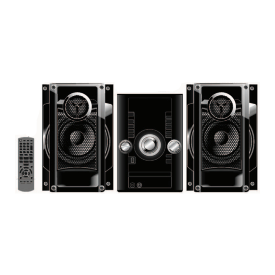
SA-AKX32LM-K
Model No.
Product Color: (K)...Black Type
© Panasonic Corporation 2011. All rights reserved.
Unauthorized copying and distribution is a violation
1
of law.
MEX1105001CE
CD Stereo System
Advertisement
Table of Contents

Related Manuals for Panasonic SA-AKX32LM-K


Summary of Contents for Panasonic SA-AKX32LM-K
-
Page 1: Table Of Contents
2.3. Service caution based on Legal restrictions (BRS1C)) 2.4. Handling Precautions for Traverse Unit 6.4. Self-Diagnostic Mode 3 Service Navigation 6.5. Self-Diagnostic Error Code Table 6.6. Sales Demonstration Lock Function © Panasonic Corporation 2011. All rights reserved. Unauthorized copying and distribution is a violation of law. - Page 2 7 Troubleshooting Guide 14.2. D-Amp Block Diagram 15 Block Diagram 7.1. Troubleshooting Guide for F61 and/ or F76 7.2. Part Location 15.1. Servo & System Control 7.3. D-Amp IC Operation & Control 15.2. IC Terminal Chart 8 Service Fixture & Tools 15.3.
-
Page 3: Safety Precautions
1 Safety Precautions 1.1. General Guidelines 1. When servicing, observe the original lead dress. If a short circuit is found, replace all parts which have been overheated or damaged by the short circuit. 2. After servicing, see to it that all the protective devices such as insulation barriers, insulation papers shields are properly installed. -
Page 4: Before Repair And Adjustment
1.4. Before Repair and Adjustment Disconnect AC power to discharge unit AC Capacitors as such (C5701, C5703, C5704, C5705, C5706, C5707, C5708) through a 10 :, 10 W resistor to ground. Caution: DO NOT SHORT-CIRCUIT DIRECTLY (with a screwdriver blade, for instance), as this may destroy solid state devices. After repairs are completed, restore power gradually using a variac, to avoid overcurrent. -
Page 5: Safety Parts Information
1.6. Safety Parts Information Safety Parts List: Modelo: SC-AKX32LM-K Safety Nombre del componente Numero de Parte CABLE TOMACORRIENTE. SJA168-1A CONECTOR TOMACORRIENTE K2AA2B000017 TRANSFORMADOR DE PODER G4DYZ0000050 TRANSFORMADOR DE ETS19AB2E6AG RESPALDO FUSIBLE PRIMARIO K5D802APA008 ERZV10V511CS CAPACITOR DE AC F1BAF1020020 CAPACITOR DE AC F0CAF224A105 CAPACITOR DE AC F0CAF104A105... -
Page 6: Warning
2 Warning 2.1. Prevention of Electrostatic Discharge (ESD) to Electrostatic Sensitive (ES) Devices Some semiconductor (solid state) devices can be damaged easily by static electricity. Such components commonly are called Elec- trostatically Sensitive (ES) Devices. Examples of typical ES devices are integrated circuits and some field-effect transistors and semiconductor "chip"... -
Page 7: Precaution Of Laser Diode
2.2. Precaution of Laser Diode Caution:... -
Page 8: Service Caution Based On Legal Restrictions
2.3. Service caution based on Legal restrictions 2.3.1. General description about Lead Free Solder (PbF) The lead free solder has been used in the mounting process of all electrical components on the printed circuit boards used for this equipment in considering the globally environmental conservation. The normal solder is the alloy of tin (Sn) and lead (Pb). -
Page 9: Handling Precautions For Traverse Unit
2.4. Handling Precautions for Traverse Unit The laser diode in the optical pickup unit may break down due to static electricity of clothes or human body. Special care must be taken avoid caution to electrostatic breakdown when servicing and handling the laser diode in the traverse unit. Cautions to Be Taken in Handling the Optical Pickup Unit 2.4.1. -
Page 10: Grounding For Electrostatic Breakdown Prevention
Grounding for electrostatic breakdown prevention 2.4.2. Some devices such as the DVD player use the optical pickup (laser diode) and the optical pickup will be damaged by static electric- ity in the working environment. Proceed servicing works under the working environment where grounding works is completed. 2.4.2.1. -
Page 11: Service Navigation
3 Service Navigation 3.1. Service Information This service manual contains technical information which will allow service personnel’s to understand and service this model. Please place orders using the parts list and not the drawing reference numbers. If the circuit is changed or modified, this information will be followed by supplement service manual to be filed with original service manual. -
Page 12: Specifications
4 Specifications ó i f i l ó i é t ñ i b i d i l é t ó s t i ó i ó i ó i ó i ó i ó i desbalanceado ó i í v Bafle í... -
Page 13: Location Of Controls And Components
5 Location of Controls and Components 5.1. Main Unit Key Button Operation... -
Page 14: Remote Control Key Button Operation
5.2. Remote Control Key Button Operation SLEEP PLAY/ AUTO OFF EXT-IN MEMOR Y RADIO SOUND D.BASS PRESET EQ EDIT DISPLAY DIMMER M ODE HI-SPEED MEMOR Y M ODE Refer to the numbers in parentheses for chapter references. Standby/on switch [ ], [ , POWER] Recording operation for USB and internal Press to switch the unit from on to standby mode... -
Page 15: Media Information
5.3. Media Information... -
Page 16: Self-Diagnostic And Special Mode Setting
6 Self-Diagnostic and Special Mode Setting 6.1. Cold-Start Here is the procedure to carry out cold-start or initialize to shipping mode. 1. Unplug AC power cord 2. Press & hold [POWER] button 3. Plug AC power cord while [POWER] button being pressed FL Display will show “_ _ _ _ _ _ _ _”... -
Page 17: Doctor Mode Table
6.2. Doctor Mode Table 6.2.1. Doctor Mode Table 1 Item Key Operation FL Display Mode Name Description Front Key Doctor Mode To enter into Doctor Mode 1.In CD Mode: Press [ ] button on main unit follow by [4] and [7] on remote control. - Page 18 6.2.2. Doctor Mode Table 2 Item Key Operation FL Display Mode Name Description Front Key Cold Start To active cold start upon next AC In Doctor Mode: power up when reset start is execute 1. Press [DISPLAY/-DIMMER] the next time. button on remote control.
-
Page 19: Reliability Test Mode (Cd Mechanism Unit (Brs1C))
6.3. Reliability Test Mode (CD Mechanism Unit (BRS1C)) Below is the process flow chart of the aging test for the CD Mechanism Unit (BRS1C). OPEN First Track Operation Access OPEN wait First Track fot 1 s Play 5 s CLOSE Last Track Operation Access... -
Page 20: Self-Diagnostic Mode
6.4. Self-Diagnostic Mode In CD Mode: Service Mode To enter into Service Mode 1.Press and hold [ ] button on main unit for 2 secs. 2.Do not release [ ] button, press and hold [ ] on the remote control for 2 secs. 3.To exit, press [POWER, button on main unit. -
Page 21: Self-Diagnostic Error Code Table
6.5. Self-Diagnostic Error Code Table Self-Diagnostic Function (Refer Section 6.4. Self-Diagnostic Mode) provides information on any problems occurring for the unit and its respective components by displaying the error codes. These error code such as U**, H** and F** are stored in memory and held unless it is cleared. -
Page 22: Sales Demonstration Lock Function
6.6. Sales Demonstration Lock Function 6.6.1. Entering into sales Demo Mode Here is the procedures to enter into Sales Demonstration Lock. Step 1: Turn on the unit. Step 2: Select to any mode function, press and hold [ ] key and follow by [ / ] key pressed within 0.5 sec. OPEN/CLOSE Step 3: Hold both [ ] and [ / ] keys for 5 sec. -
Page 23: Troubleshooting Guide
7 Troubleshooting Guide 7.1. Troubleshooting Guide for F61 and/ or F76 This section illustrates the checking procedures when upon detecting the error of “F61” and “F76” after power up of the unit.It is for purpose of troubleshooting and checking in SMPS,D-Amp & Main P.C.B.. -
Page 24: Part Location
7.2. Part Location 7.2.1. SMPS P.C.B. AC Inlet: P5701 Fuse: Switching Regulator IC: IC5799 Switching Regulator Photocoupler: IC: IC5701 Thermistor: PC5702, PC5799 TH5860 Rectifier Diode: D5801, D5802 Transformer: Connector: T5701 CN5802 Photocoupler: PC5720 Fig. 1 SMPS P.C.B. - Page 25 7.2.2. Main P.C.B. Voltage Regulator IC: IC2010 DC/DC Converter IC: Connector: IC2011 ZJ2007 Fig. 2 Main P.C.B.
- Page 26 7.2.3. D-Amp P.C.B. Audio Digital Amp IC: IC5900 Fig. 3 D-Amp P.C.B.
-
Page 27: D-Amp Ic Operation & Control
7.3. D-Amp IC Operation & Control D-AMP IC Operation & Control 1) D-AMP IC (C1AB00000497) was used for this model. 2) Three control pins (signal send from micro-processor IC) were used to control the D-AMP IC operation such as muting, standby and normal operation. They are described as below: - Pin no Signal name Function... - Page 28 1170 ~ 1250 1260 ~ 1450 1460 ~ 1540 1550 ~ 1710 Table 4: F_HOP Control during 10 kHz Step Note: During activating, the 3 control pins namely MUTE_F, MUTE_A and MODE_DA must be used to cover the “Pop” sound cause by F-HOP switching.
-
Page 29: Service Fixture & Tools
8 Service Fixture & Tools 8.1. Service Tools and Equipment Prepare service tools before process service position. Service Tools Remarks Main P.C.B. (ZJ2007) - SMPS P.C.B. (CN5802) REXX1206 (15P Cable Wire) -
Page 30: Disassembly And Assembly Instructions
9 Disassembly and Assembly Instructions • Illustration is based on SA-AKX32PH-K Caution Note: • This section describes the disassembly and/or assembly procedures for all major printed circuit boards & main components for the unit. (You may refer to the section of “Main components and P.C.B Locations” as described in the service manual) •... -
Page 31: Disassembly Flow Chart
9.1. Disassembly Flow Chart 9.3. Top Cabinet 9.4. Tuner P.C.B. 9.16. SMPS P.C.B. 9.12. Main P.C.B. 9.5. Front Panel 9.17. Switching Regulator Unit IC (IC5701) 9.13. Voltage Regulator IC (IC2010) 9.18. Rectifier Diode 9.6. Jupiter P.C.B. (D5702) 9.14. D-Amp .P.C.B. 9.19. -
Page 32: Main Components And P.c.b. Locations
9.2. Main Components and P.C.B. Locations... -
Page 33: Disassembly Of Top Cabinet
9.3. Disassembly of Top Cabinet Step 4 Slightly lift up both side of Top Cabinet in an outward direction as shown. Step 1 Remove 2 screws on each side. Step 5 Remove Top Cabinet. Step 2 Remove 5 screws. Step 3 Slightly pull both side of Top Cabinet outwards as arrow shown. -
Page 34: Disassembly Of Tuner P.c.b
9.4. Disassembly of Tuner P.C.B. 9.5. Disassembly of Front Panel Unit • Refer to “Disassembly of Top Cabinet”. • Refer to “Disassembly of Top Cabinet”. Step 1 Remove 1 screw. Step 1 Detach 30P FFC at the connector (CN2000) on Jupiter P.C.B. - Page 35 Step 3 Push inwards slightly at the Bottom Chassis and release Step 5 Push inwards slightly at the Bottom Chassis and release tab at left side of Front Panel Unit.. tab at right side of Front Panel Unit. Step 4 Release tab at bottom. Step 6 Remove Front Panel Unit.
-
Page 36: Disassembly Of Jupiter P.c.b
9.6. Disassembly of Jupiter P.C.B. Step 3 Detach 7P connector (CN503) on Jupiter P.C.B. from 7P connector (CN6003) on USB P.C.B.. • Refer to “Disassembly of Top Cabinet”. Step 4 Remove Jupiter Unit. • Refer to “Disassembly of Front Panel Unit”. Step 1 Detach 30P FFC at the connector (CN601) on Jupiter P.C.B. -
Page 37: Disassembly Of Panel P.c.b
9.7. Disassembly of Panel P.C.B. Step 4 Release catches by following the sequences (1-6). • Refer to “Disassembly of Top Cabinet”. • Refer to “Disassembly of Front Panel Unit”. • Refer to “Disassembly of Jupiter P.C.B.”. Step 1 Remove the Volume Knob. Step 2 Remove the Track Knob. -
Page 38: Disassembly Of Remote Sensor P.c.b
Step 6 Desolder 12pins at (ZJ6002A) on Panel P.C.B. 9.8. Disassembly of Remote Sensor Step 7 Remove the Panel P.C.B. P.C.B. • Refer to “Disassembly of Top Cabinet Unit”. • Refer to “Disassembly of Front Panel Unit”. • Refer to “Disassembly to Jupiter P.C.B.”. •... -
Page 39: Disassembly Of Usb P.c.b
9.9. Disassembly of USB P.C.B. 9.10. Disassembly of Music Port P.C.B. • Refer to “Disassembly of Top Cabinet”. • Refer to “Disassembly of Front Panel Unit”. • Refer to “Disassembly of Top Cabinet”. • Refer to “Disassembly of Jupiter P.C.B”. •... -
Page 40: Disassembly Of Cd Lid
Caution: During assembling, ensure the 2P Cable Wire is 9.11. Disassembly of CD Lid dressed into the outer slot properly. • Refer to “Disassembly of Top Cabinet”. • Refer to “Disassembly of Front Panel Unit”. Step 1 Remove the spring as arrow shown in order of sequence (1) to (3). -
Page 41: Disassembly Of Main P.c.b
9.12. Disassembly of Main P.C.B. Step 6 Remove 1 screw. Step 7 Detach Main P.C.B. from Rear Panel according to arrow • Refer to “Disassembly of Top Cabinet”. shown. • Refer to “Disassembly of Front Panel Unit”. Step 1 Detach 2P Wire at the connector (CN2006) on Main P.C.B.. -
Page 42: Disassembly Of D-Amp P.c.b
9.14. Disassembly of D-Amp P.C.B. Caution: During assembling, ensure that earth plate is bended flat against the Main P.C.B. properly when inserted Refer to “Disassembly of Top Cabinet”. to locators. Refer to “Disassembly of Front Panel Unit”. Step 1 Step 2 Step 3... - Page 43 Step 4 Remove 1 screw. Caution: During assembling, ensure that D-Amp Bracket is seated on the locator of Inner Chassis properly. Step 5 Slightly lift up & remove D-Amp Unit as arrow shown. Step 6 Detach 12P FFC at the connector (CN5902) on D-Amp P.C.B..
-
Page 44: Replacement Of Audio Digital Amp Ic
Step 7 Remove 1 screw. Step 2 Release 2 catches of Heatsink Clip. Step 8 Remove D-Amp P.C.B.. Caution: During releasing of 2 catches, avoid touching the Heatsink, due to high temperature. Caution: Keep the D-Amp Brackets in safe place, place it back during assembling. -
Page 45: (Ic5900)
9.15.2. Assembly of Audio Digital Amp IC 9.16. Disassembly of SMPS P.C.B. (IC5900) • Refer to “Disassembly of Top Cabinet.”. Step 1 Apply grease to the Heatsink. • Refer to “Disassembly of Front Panel Unit”. Step 2 Fix the Audio Digital Amp IC (IC5900) on D-Amp P.C.B. •... -
Page 46: Replacement Of Switching Regulator Ic (Ic5701)
Step 5 Flip the SMPS P.C.B. and position it according to dia- 9.17. Replacement of Switching Reg- gram shown. ulator IC (IC5701) Step 6 Position SMPS P.C.B. on the insulated material. Step 7 Desolder 2 Wire pins, TL7 (Black), TL8 (Red) wires pin. •... - Page 47 Step 2 Remove 1 screw. Step 4 Solder pins of the Switching Regulator IC (IC5701) on Step 3 Remove the Switching Regulator IC (IC5701). the solder side of SMPS P.C.B.. Caution: Avoid touching the Heatsink A due to its high temperature after prolonged use.
-
Page 48: Replacement Of Rectifier Diode (D5702)
9.18. Replacement of Rectifier Diode Step 3 Remove 1 screw at Switching Regulator IC (IC5701). Step 4 Remove the Heatsink A with Rectifier Diode (D5702). (D5702) Step 5 Remove 1 screw. • Refer to “Disassembly of SMPS P.C.B.”. Step 6 Remove the Rectifier Diode (D5702) from the Heatsink Caution: Avoid touching the Heatsink A due to its high 9.18.1. - Page 49 9.18.2. Assembly of Rectifier Diode Step 5 Solder pins of the Rectifier Diode (D5702) on the solder side of SMPS P.C.B.. (D5702) Step 6 Solder pins of the Heatsink A on the solder side of Step 1 Apply grease to the Heatsink A. SMPS P.C.B..
-
Page 50: Replacement Of Rectifier Diode (D5801)
9.19. Replacement of Rectifier Diode 9.19.2. Assembly of Rectifier Diode (D5801) (D5801) Step 1 Apply grease to the Heatsink B. • Refer to “Disassembly of SMPS P.C.B.”. Step 2 Fix the Rectifier Diode (D5801) on SMPS P.C.B. Caution: Ensure pins of the Rectifier Diode (D5801) is properly inserted on SMPS P.C.B. -
Page 51: Replacement Of Rectifier Diode (D5802)
9.20. Replacement of Rectifier Diode 9.20.2. Assembly of Rectifier Diode (D5802) (D5802) Step 1 Apply grease to the Heatsink B. • Refer to “Disassembly of SMPS P.C.B.”. Step 2 Fix the Rectifier Diode (D5802) on SMPS P.C.B.. Caution: Ensure pins of the Rectifier Diode (D5802) is properly inserted on SMPS P.C.B. -
Page 52: Replacement Of Rectifier Diode (D5803)
9.21. Replacement of Rectifier Diode 9.21.2. Assembly of Rectifier Diode (D5803) (D5803) Step 1 Apply grease to the Heatsink B. • Refer to “Disassembly of SMPS P.C.B.”. Step 2 Fix Rectifier Diode (D5803) on SMPS P.C.B. Caution: Ensure pins of the Rectifier Diode (D5803) are properly inserted on SMPS P.C.B. -
Page 53: Disassembly Of Cd Mechanism Unit (Brs1C)
9.22. Disassembly of CD Mecha- Step 4 nism Unit (BRS1C) Refer to “Disassembly of Top Cabinet”. Refer to “Disassembly of Front Panel Unit”. Refer to “Disassembly of D-Amp P.C.B.”. Step 1 Step 2 Step 3... - Page 54 Step 6 Lift up SMPS Inner Chassis Unit. Step 7 Remove 2 screws. Caution: During assembling, ensure that SMPS Inner Chassis is catched onto Rear Panel properly. Step 8 Lift up & upset the CD Mechanism Unit (BRS1C) as shown. Step 9 Detach 27P FFC at the connector (CN7002) on CD Servo P.C.B..
-
Page 55: Disassembly Of Rear Panel
9.23. Disassembly of Rear Panel Step 3 Refer to “Disassembly of Top Cabinet”. Refer to “Disassembly of Tuner P.C.B.”. Step 1 Step 4 Step 5 Step 2... -
Page 56: Replacement Of Traverse Unit
10 Replacement of Traverse Unit 10.1. Disassembly of Traverse Unit Step 2: Slide the tray out fully. • Refer to “Disassembly of CD Mechanism Unit (BRS1C)”. Caution: Refer to “2.4 Handling Precaution for Traverse Unit” to prevent static damage to the Optical Pickup Unit. Note: 1. - Page 57 Step 4: Release the guide as shown & slide the Traverse Slide Step 6: Lift the Traverse Unit by approximately 45q. Plate to the end. Step 7: Slide out the traverse unit as arrow shown. Step 5: Detach 5P FFC at the connector (CN7003) on CD Servo P.C.B..
-
Page 58: Assembly Of Traverse Unit
10.2. Assembly of Traverse Unit Step 2: Slot the Traverse Unit at approximately 45q into the mecha chassis as arrow shown. Step 1: Release the guide as shown & slide the Traverse Slide Plate to the end. - Page 59 Step 3: Ensure the Traverse Unit seated properly onto the Step 6: Slide the Traverse Slide Plate unit it stop at the Guide.. Groove.. Step 7: Slot the Tray into the guides as Picture shown. Step 4: Slide Traverse Slide Plate to lock the Traverse Unit as shown.
-
Page 60: Disassembly Of Cd Servo P.c.b
Step 8: Ensure the guides is align with the groove when sliding 10.3. Disassembly Servo the tray in. P.C.B. • Refer to “Disassembly of CD Mechanism Unit (BRS1C)”. • Refer to “Replacement of Traverse Unit”. Caution: It is required to short the circuit. Step 1: Solder the 3 solder points. - Page 61 Caution 2: During assembling, desolder the solder points. Step 5 Slightly lift up the CD Servo P.C.B. Step 6 Flip the CD Servo P.C.B. Step 2 Remove 3 screws. Step 3 Desolder 4 pins. Step 4 Detach 5P FFC at the connector (CN7003) on CD Servo P.C.B..
- Page 62 Step 9 Ground the 24P FFC with a short pin.
-
Page 63: Service Position
11 Service Position 11.2. Checking and Repairing of D- Amp P.C.B. Note: For description of the disassembly procedures, see the Section 9. Step 1 Remove Top Cabinet. Step 2 D-Amp P.C.B. can be checked & repaired at its original 11.1. Checking and Repairing of position. -
Page 64: Checking And Repairing Of Jupiter P.c.b
11.4. Checking and Repairing of 11.4.2. Checking and Repairing side A of Jupiter P.C.B. Jupiter P.C.B. Step 1 Remove Top Cabinet. 11.4.1. Checking and Repairing side B of Step 2 Remove Front Panel Unit. Step 3 Remove the Jupiter P.C.B. Jupiter P.C.B. - Page 65 11.5. Checking and Repairing of Step 10 Extend the Cable Wire with extension Cable Wire (REXX1206) (15P Cable Wire from ZJ2007 to CN5802). SMPS P.C.B. Step 11 Connect 6P Cable Wire to the connector (CN5801) on Step 1 Remove Top Cabinet. SMPS P.C.B..
-
Page 66: Checking And Repairing Of Cd Servo P.c.b
11.6. Checking and Repairing of CD Step 13 Attach 27P FFC to the connector (CN7002) on CD Servo P.C.B.. Servo P.C.B. Step 14 CD Servo P.C.B. can be checked and repaired as dia- Step 1 Remove Top Cabinet. gram shown. Step 2 Remove Front Panel Unit. -
Page 67: Voltage & Waveform Chart
12 Voltage & Waveform Chart Note: • Indication Voltage Values are in standard values for the unit measured by the DC electronic circuit tester (high-impedance) with the chassis taken as standard. Therefore, there may exist some errors in voltage values, depending on the internal impedance of the DC circuit tester. •... -
Page 68: Main P.c.b
12.2. Main P.C.B. (1/3) IC2003 REF NO. MODE POWER ON STANDBY IC2003 REF NO. MODE POWER ON 3.2 STANDBY REF NO. IC2003 MODE POWER ON STANDBY IC2003 REF NO. MODE POWER ON STANDBY IC2003 REF NO. MODE POWER ON STANDBY IC2006 REF NO. -
Page 69: Main P.c.b
12.3. Main P.C.B. (2/2) Q2020 Q2021 Q2022 Q2023 Q2033 REF NO. MODE POWER ON 12.0 16.1 16.1 16.4 16.5 11.6 TUNER 12.0 16.1 16.1 16.4 16.5 11.6 QR2005 QR2006 REF NO. MODE POWER ON TUNER IC2000 REF NO. MODE CD PLAY STANDBY IC2000 REF NO. -
Page 70: Panel P.c.b
12.5. Panel P.C.B. IC6001 REF NO. MODE POWER ON 0.1 -14.4 -14.3 -18.2 -22.1 -20.2 -22.1 -18.2 STANDBY -12.5 -16.3 -14.3 -22.1 -20.2 -22.1 -12.4 IC6001 REF NO. MODE POWER ON -12.4 -22.1 -22.1 -20.1 -14.2 -22.1 -18.2 -22.1 -24.1 -24.6 -22.5 -22.4 -22.4 -22.4 -22.4 -22.4 -22.4 -22.4 -22.4 -22.4 STANDBY -12.4 -22.1 -22.1 -20.1 -12.2 -20.1 -13.3 -22.1 -24.1 -24.6 -22.5 -22.4 -22.4 -22.4 -22.4 -22.4 -22.4 -22.4 -22.4 -22.4 IC6001... -
Page 71: Jupiter P.c.b
12.7. Jupiter P.C.B. (1/3) IC503 REF NO. MODE CD PLAY STANDBY IC551 REF NO. MODE CD PLAY STANDBY IC552 REF NO. MODE CD PLAY STANDBY REF NO. IC701 MODE CD PLAY STANDBY IC701 REF NO. MODE CD PLAY STANDBY IC701 REF NO. - Page 72 12.8. Jupiter P.C.B. (2/3) IC801 REF NO. MODE CD PLAY STANDBY REF NO. IC801 MODE CD PLAY STANDBY IC801 REF NO. MODE CD PLAY STANDBY IC801 REF NO. MODE CD PLAY STANDBY IC801 REF NO. MODE CD PLAY STANDBY IC801 REF NO.
-
Page 73: Jupiter P.c.b
12.9. Jupiter P.C.B. (3/3) IC802 REF NO. MODE CD PLAY STANDBY REF NO. Q801 MODE CD PLAY STANDBY SA-AKX32 JUPITER P.C.B. 12.10. D-Amp P.C.B. REF NO. IC5900 MODE CD PLAY 35.1 -35.1 -26.7 35.4 16.8 -35.3 -25.3 -35.3 17.0 35.4 -35.1 -35.1 35.0 STANDBY 35.1... -
Page 74: Smps P.c.b
12.11. SMPS P.C.B. IC5701 REF NO. MODE POWER ON 164.8 19.1 STANDBY 164.8 19.1 IC5799 REF NO. MODE POWER ON 5.9 11.0 164.2 STANDBY 11.0 164.2 REF NO. IC5801 MODE POWER ON 2.4 -30.0 STANDBY -30.0 IC5899 REF NO. MODE POWER ON 1.2 STANDBY Q5720... -
Page 75: Waveform Table
12.12. Waveform Table 0.1Vp-p(200usec/div) 4Vp-p(200usec/div) 0.2Vp-p(200usec/div) 1.3Vp-p(200usec/div) 2Vp-p(200usec/div) 2.4Vp-p(200usec/div) 3.6Vp-p(50nsec/div) 2.2Vp-p(50nsec/div) 1.4Vp-p(5usec/div) 2.8Vp-p(5usec/div) 1.9Vp-p(200usec/div) 100Vp-p(1usec/div) 1.5Vp-p(1usec/div) -
Page 76: Illustration Of Ics, Transistor And Diode
13 Illustration of ICs, Transistor and Diode Este material se encuentra sin programar, debe ser programado. MN101EF16KXW C3ABQY000058 RFKWFAKX32J0 C0ABBB000230 (8P) C3EBFY000006 (8P) (100P) (64P) (48P) C0FBAK000026 (16P) MN2WS0042NA (216P) C0ABBA000159 (8P) C0FBBY000027 (16P) C0HBB0000057 (44P) C1AB00003256 (52P) MN6627553PA (80P) No.1 No.1 No.1... -
Page 77: Simplified Block Diagram
14 Simplified Block Diagram 14.1. Overall Simplified Block Diagram... -
Page 78: D-Amp Block Diagram
14.2. D-Amp Block Diagram Subwoofer AMP (15mA) FROM Headphone SMPS Amp (15mA) DIGITAL AMP IC +/-VCC = 35V, (NXP) Bi-AMP filter (15mA) IC2010 +18V 245mA Regulator (11.5V ~ 19V) +12V (403mA) 1A Max BACKUP Reg4 +3.3V 200mA 9.9V 7.5V CD module motor +7.5V (200mA) discrete... -
Page 79: Block Diagram
15 Block Diagram 15.1. Servo & System Control : USB SIGNAL LINE : CD AUDIO INPUT SIGNAL LINE : AUDIO OUTPUT SIGNAL LINE MAIN P.C.B. JUPITER P.C.B. IC801 MN2WS0042NA RIPPING AUDIO LSI CD MECHANISM UNIT CD SERVO P.C.B. BRS1C IC7101 FL DATA CN2000 CN601 FL DATA... - Page 80 : CD AUDIO INPUT SIGNAL LINE : AUDIO OUTPUT SIGNAL LINE : USB SIGNAL LINE MAIN P.C.B. IC2003 RFKWMAKX32M0 MICRO PROCESSOR IC6001 PANEL P.C.B. FL6000 C0HBB0000057 FL DISPLAY FL DISPLAY DRIVER MUTE A MUTE A MUTE A MUTE F FL DATA CN2003 CN6001 FL DOUT...
-
Page 81: Ic Terminal Chart
15.2. IC Terminal Chart IC751 IC801 IC701 IC801 SDRAM RIPPING AUDIO LSI FLASH MEMORY RIPPING AUDIO LSI SIGNAL NAME SIGNAL NAME PORT NAME PIN NO PIN NO PORT NAME PORT NAME PIN NO PIN NO PORT NAME SDRA0 DQ15 HIR0 SDRA1 HIR1 SDRA2... -
Page 82: Audio
15.3. Audio : CD AUDIO INPUT SIGNAL LINE : AUX/TUNER/MUSIC PORT AUDIO INPUT SIGNAL LINE : AUDIO OUTPUT SIGNAL LINE : AM SIGNAL LINE : FM SIGNAL LINE MAIN P.C.B. PANEL P.C.B. IC2000 C1AB00003256 MUSIC PORT P.C.B. JK2000 JK6001 AUX L 38 IN3B HP SW HP SW... - Page 83 : CD AUDIO INPUT SIGNAL LINE : AUX/TUNER/MUSIC PORT AUDIO INPUT SIGNAL LINE : AUDIO OUTPUT SIGNAL LINE : AM SIGNAL LINE : FM SIGNAL LINE MAIN P.C.B. D-AMP P.C.B. IC5900 SPEAKERS C1BA00000497 POWER AMPLIFIER CN2011 CN5902 FRONT R FRONT R FRONT R 21 IN2- BOOT2 15...
-
Page 84: Power Supply
& & “ : ” *... - Page 85 MAIN P.C.B. JUPITER P.C.B. CN2000 CN601 12,16 15,19 IC503 C0DBZHE00026 HIGH SIDE SWITCH VBUS TO POWER SUPPLY 1 IN OUT 5 VBUS FROM/TO BLOCK (1/2) SERVO & OC 4 SYSTEM CONTROL EN 3 CD3.3V CN2000 CN601 D+3.3V , LSI+3.3V D+3.3V, LSI+3.3V 3.3V IC802 C0DBZYY00293...
- Page 86 " : " *...
-
Page 87: Schematic Diagram
17 Schematic Diagram 17.1. Schematic Diagram Notes This schematic diagram may be modified at any time with the development of new technology. Notes: S5701: S6001: S6002: S6003: S6004: S6005: S6006: S6007: S6008: S6009: S6010: S6011: S6013: S6014: S6015: S6016: VR6001: VR6002: Resistor Capacitor... -
Page 88: Cd Servo Circuit
17.2. CD Servo Circuit SCHEMATIC DIAGRAM - 1 CD SERVO CIRCUIT : +B SIGNAL LINE : CD AUDIO INPUT SIGNAL LINE TO CD SERVO CIRCUIT (2/2) S7201 RESET CN7003 C7264 SW_CLOSE LOADING MOTOR P.C.B. SW_OPEN C7614 C7615 K7701 C7613 LDM- LDM- (CD MECHANISM UNIT BRS1C) 6.3V47... - Page 89 SCHEMATIC DIAGRAM - 2 CD SERVO CIRCUIT : +B SIGNAL LINE : CD AUDIO INPUT SIGNAL LINE TO CD SERVO CIRCUIT (1/2) TP11 K7335 7.5V R7332 LOADING R842 R841 M7302* TRAVERSE MOTOR TRVP R7323 3.3K R7331 R7327 5.6K R7349 100K C7352 C7338 R7322...
-
Page 90: Main Circuit
17.3. Main Circuit SCHEMATIC DIAGRAM - 3 MAIN CIRCUIT : +B SIGNAL LINE : -B SIGNAL LINE : CD/DVD AUDIO INPUT SIGNAL LINE : AUX/TUNER/MUSIC PORT AUDIO INPUT SIGNAL LINE : AUDIO OUTPUT SIGNAL LINE C2061 R2372 50V1 K2009 Q2040 B1ABCF000176 TO MAIN C2082... - Page 91 SCHEMATIC DIAGRAM - 4 MAIN CIRCUIT : +B SIGNAL LINE : -B SIGNAL LINE : CD/DVD AUDIO INPUT SIGNAL LINE : AUX/TUNER/MUSIC PORT AUDIO INPUT SIGNAL LINE : AUDIO OUTPUT SIGNAL LINE TO MAIN CIRCUIT (1/8) CN2011 FR_CH FRONT R SIGNAL A_GND FL_CH FRONT L...
- Page 92 SCHEMATIC DIAGRAM - 5 MAIN CIRCUIT : +B SIGNAL LINE : -B SIGNAL LINE : CD/DVD AUDIO INPUT SIGNAL LINE : AUX/TUNER/MUSIC PORT AUDIO INPUT SIGNAL LINE : AUDIO OUTPUT SIGNAL LINE IC2010 C0CAAKG00046 +12V VOLTAGE REGULATOR M+12V Q2022 B1BACD000018 C2229 C2234 D2018...
- Page 93 SCHEMATIC DIAGRAM - 6 MAIN CIRCUIT : +B SIGNAL LINE : -B SIGNAL LINE : CD/DVD AUDIO INPUT SIGNAL LINE : AUX/TUNER/MUSIC PORT AUDIO INPUT SIGNAL LINE : AUDIO OUTPUT SIGNAL LINE IC2006 D2006 C3EBFY000006 B0ACCK000012 EEPROM C2115 R2105 100K R2097 R2182 C2148...
- Page 94 SCHEMATIC DIAGRAM - 7 MAIN CIRCUIT : +B SIGNAL LINE : -B SIGNAL LINE : CD/DVD AUDIO INPUT SIGNAL LINE : AUX/TUNER/MUSIC PORT AUDIO INPUT SIGNAL LINE : AUDIO OUTPUT SIGNAL LINE TO MAIN CIRCUIT (1/8) TO MAIN CIRCUIT (6/8) C2117 R2137 R2150...
- Page 95 SCHEMATIC DIAGRAM - 8 MAIN CIRCUIT : +B SIGNAL LINE : -B SIGNAL LINE : CD/DVD AUDIO INPUT SIGNAL LINE : AUX/TUNER/MUSIC PORT AUDIO INPUT SIGNAL LINE : AUDIO OUTPUT SIGNAL LINE TO MAIN TO MAIN CIRCUIT (2/8) CIRCUIT (5/8) R2268 R2272 2.7K...
- Page 96 SCHEMATIC DIAGRAM - 9 MAIN CIRCUIT : +B SIGNAL LINE : -B SIGNAL LINE : CD/DVD AUDIO INPUT SIGNAL LINE : AUX/TUNER/MUSIC PORT AUDIO INPUT SIGNAL LINE : AUDIO OUTPUT SIGNAL LINE TO MAIN CIRCUIT (3/8) DC16V Q2033 B1AAJC000019 POWER SUPPLY IC2012 C0ABBB000230 R2379...
- Page 97 SCHEMATIC DIAGRAM - 10 MAIN CIRCUIT : +B SIGNAL LINE : -B SIGNAL LINE : CD/DVD AUDIO INPUT SIGNAL LINE : AUX/TUNER/MUSIC PORT AUDIO INPUT SIGNAL LINE : AUDIO OUTPUT SIGNAL LINE TO MAIN CIRCUIT (4/8) CN2009 CD_CLOSE_SW CD_CLOSE_SW CD_L CD_LOUT AGND CD_R...
-
Page 98: Panel Circuit
17.4. Panel Circuit SCHEMATIC DIAGRAM - 11 PANEL CIRCUIT : +B SIGNAL LINE : -B SIGNAL LINE : MUSIC PORT AUDIO INPUT SIGNAL LINE : AUDIO OUTPUT SIGNAL LINE FL6000 A2BB00000177 FL DISPLAY C6020 C6037 1000P C6035 1000P C6034 1000P C6033 1000P C6032... -
Page 99: Music Port Circuit
SCHEMATIC DIAGRAM - 12 PANEL CIRCUIT : +B SIGNAL LINE : -B SIGNAL LINE : MUSIC PORT AUDIO INPUT SIGNAL LINE : AUDIO OUTPUT SIGNAL LINE VR6001 VR6002 EVEKE2F3524B K9AA012Y0004 VOLUME ALBUM/TRACK 1 2 3 1 2 3 KEY1 CN6005 KEY2 DGND REMOTE SENSOR... - Page 100 17.5. Music Port Circuit SCHEMATIC DIAGRAM - 13 MUSIC PORT CIRCUIT : +B SIGNAL LINE : MUSIC PORT AUDIO INPUT SIGNAL LINE : AUDIO OUTPUT SIGNAL LINE ZJ6001* JK6002 TO JUPITER SHIELD L6003 J0JBC0000019 L6004 J0JBC0000019 L6008 J0JBC0000019 ZJ6002* MUSIC PORT C6040 C6045 C6047...
-
Page 101: Remote Sensor, Usb & Tuner Circuit
17.6. Remote Sensor, USB & Tuner Circuit SCHEMATIC DIAGRAM - 14 REMOTE SENSOR CIRCUIT USB CIRCUIT : +B SIGNAL LINE : +B SIGNAL LINE : USB SIGNAL LINE IR6000 B3RAB0000084 REMOTE CONTROL SENSOR CN6004 CN6003 VBUS VBUS USB PORT JUPITER CIRCUIT DGND (CN503) DGND... -
Page 102: Jupiter Circuit
17.7. Jupiter Circuit SCHEMATIC DIAGRAM - 15 JUPITER CIRCUIT : +B SIGNAL LINE : AUDIO OUTPUT SIGNAL LINE : USB SIGNAL LINE TO JUPITER IC701 CIRCUIT (2/4) RFKWFAKX32J0 FLASH MEMORY FA16 FA17 FA15 BYTE# FA14 FA13 DQ15 FA12 FA11 DQ14 FA10 DQ13 FA20... - Page 103 SCHEMATIC DIAGRAM - 16 JUPITER CIRCUIT : AUDIO OUTPUT SIGNAL LINE : +B SIGNAL LINE : USB SIGNAL LINE TO JUPITER CIRCUIT (1/4) C768 169 168 155 154 151 150 147 146 143 142 139 138 135 134 [130] RFU DAT0 RX761 D1H82204A024...
- Page 104 SCHEMATIC DIAGRAM - 17 JUPITER CIRCUIT : +B SIGNAL LINE : AUDIO OUTPUT SIGNAL LINE : USB SIGNAL LINE TO JUPITER TO JUPITER CIRCUIT (4/4) CIRCUIT (1/4) C753 0.01 C752 0.01 C751 0.01 IC751 LSI+3.3V C3ABQY000058 SDRAM RX840 206 205 202 201 196 195 194 193...
- Page 105 SCHEMATIC DIAGRAM - 18 JUPITER CIRCUIT : +B SIGNAL LINE : AUDIO OUTPUT SIGNAL LINE : USB SIGNAL LINE TO JUPITER TO JUPITER CIRCUIT (3/4) CIRCUIT (2/4) CN601 LB640 J0JDC0000104 GPIO0 CD RESET REST SW LB639 J0JDC0000104 REST SW SRDAT2 LB638 J0JDC0000104 CD SRDATA2...
-
Page 106: D-Amp Circuit
17.8. D-Amp Circuit SCHEMATIC DIAGRAM - 19 D-AMP CIRCUIT : +B SIGNAL LINE : -B SIGNAL LINE : AUDIO OUTPUT SIGNAL LINE IC5900 C1BA00000497 POWER AMPLIFIER C5918 C5921 C5923 C5924 C5928 C5933 330P 220P 0.015 0.015 C5938 C5939 C5943 TH5900 330P D4CC11040013 C5927... -
Page 107: Smps Circuit
17.9. SMPS Circuit SCHEMATIC DIAGRAM - 20 SMPS CIRCUIT : +B SIGNAL LINE : -B SIGNAL LINE CN5801 +35V_SENSE +35V_SENSE D-AMP CIRCUIT SYS_GND (ZJ5901*) SYS_GND IN SCHEMATIC -35V_SENSE DIAGRAM - 19 -35V_SENSE FOR PH FOR PN -37V -37V TO SMPS CIRCUIT (2/2) CN5802 AM_BEATPROOF... - Page 108 . . . “ : ” * Nota: Para el valor y clave de cada componente referirse a; "Lista de partes Eléctricas" a partir de la página 122.
-
Page 109: Printed Circuit Board
18 Printed Circuit Board 18.1. CD Servo P.C.B. CD SERVO P.C.B. (REPX0919A) CN7001 (TO OPTICAL PICKUP UNIT (CD MECHANISM UNIT BRS1C)) Q7601 TP64 TP63 R7601 TP14 M7302* C7601 (SPL MOTOR) R7650 C7670 C7701 TP16 TP39 K7024 R7761 C7614 C7107 TP20 K7127 C7142 R7713... - Page 110 PM11X322A) " : " *...
- Page 111 PM11X322A) " : " *...
- Page 112 , t r & " : " *...
-
Page 113: Jupiter P.c.b
18.5. Jupiter P.C.B. JUPITER P.C.B. (RFKBX0922B) C837 X802 R849 R801 R655 R876 RX656 R807 R843 R654 C515 C852 C836 C835 C833 R844 R653 Q801 R892 C834 D802 IC802 R893 R527 C801 R701 R872 C513 RX839 C811 C829 C802 C808 C828 R806 C803 RX804... -
Page 114: Smps & D-Amp P.c.b
& PM11X320A) PM11X321A) " : " *... -
Page 115: Terminal Function Of Ics
19 Terminal Function of ICs 19.1. IC2003 (*MN101EF16KXW): IC MICRO-PROCESSOR... - Page 116 19.2. IC6001(C0HBB0000057): IC FL Driver Terminal Name Function No Connection No Connection No Connection No Connection Oscillator Input No Connection Data Input Clock Input Serial Interface Strobe Pin Key Data Input 1 Key Data Input 2 Power Supply (+5V) O Segment Output 1 O Segment Output 2 O Segment Output 3 O Segment Output 4...
-
Page 117: Exploded View And Replacement Parts List
20 Exploded View and Replacement Parts List 20.1. Exploded View and Mechanical replacement Part List 20.1.1. Cabinet Parts Location CN503 CN601 (PANEL P.C.B.) (JUPITER P.C.B.) CN6005 T6000 FL6000 CN6001 VR6001 *ZJ6002A VR6002 CN6006 IR6000 (REMOTE SENSOR P.C.B.) CN6003 CN6004 (USB P.C.B.) JK6002 10-1 10-1... - Page 118 CN2006 T5701 *ZJ2007 *SMALL HEATSINK UNIT *HEATSINK UNIT B CN2002 CN2011 11 ^11 CN2003 *HEATSINK UNIT A CN2009 CN2010 T5751 *D-AMP HEATSINK UNIT ^S5701 P5701 CN2002 *TL7 JK2000 *TL6 CN5802 (MAIN P.C.B.) *TL8 *TL5 ZJ2000 CN5801 (SMPS P.C.B.) (^VOLTAGE SELECTOR P.C.B.) (D-AMP P.C.B.) JK5901...
- Page 119 N2QAYB000637 SJA168-1A RQTM0183-1 N1DYYYY00010 RSAX0002 R P G M 0 2 6 6 ) RPNM0232T ) RPNM0232B...
- Page 120 20.1.3. Mechanical Replacement Part List...
-
Page 122: Electrical Replacement Part List
20.2. Electrical Replacement Part List... - Page 123 Lista de Partes Eléctrica Safety Ref No. Part No. Part Name & Description REPM11X320A CONJUNTO MANUAL SMPS AKX32 C5727 F1B3A3320012 CAPACITOR C5712 F2B2D5610024 CAPACITOR C5808 F2A1H2220043 E-Cap C5805 F2A1H2220043 E-Cap D5802 B0ABSM000008 DIODO D5801 B0ABSM000008 DIODO T5751 ETS19AB2E6AG Backup Switching Transformer T5701 G4DYZ0000050 39V trans (high power) PN...
- Page 124 R5803 ERJ3RBD103V RESISTENCIA CHIP PEL CULA R5814 ERJ3GEYJ822V RESISTENCIA CHIP PEL CULA R5806 ERJ3GEYJ153V RESISTENCIA CHIP PEL CULA R5808 ERJ6GEYJ222V R.CHIP R5802 ERJ3RBD103V RESISTENCIA CHIP PEL CULA R5809 ERJ6GEYJ331V R.CHIP R5817 ERJ3GEYJ331V RESISTENCIA CHIP PEL CULA R5810 ERJ3GEYJ331V RESISTENCIA CHIP PEL CULA R5800 ERJ6GEYJ153V R.CHIP...
- Page 125 W5521 Z-W6NL ALAMBRE JUMPER W5520 Z-W6NL ALAMBRE JUMPER W5528 Z-W6NL ALAMBRE JUMPER W5529 Z-W6NL ALAMBRE JUMPER W5533 Z-W6NL ALAMBRE JUMPER W5535 Z-W6NL ALAMBRE JUMPER W5538 Z-W6NL ALAMBRE JUMPER W5532 Z-W6NL ALAMBRE JUMPER W5518 Z-W6NL ALAMBRE JUMPER W5537 Z-W6NL ALAMBRE JUMPER W5530 Z-W6NL ALAMBRE JUMPER...
- Page 126 TH5702 D4CAA2R20001 Termistor ZA5703 RXXX0104 HEATSINK UNIT B RAIM11X321A CONJUNTO D-AMP AKX32 REPM11X321A CONJUNTO MANUAL D-AMP AKX32 CN5902 K1MY12AA0124 CONECTOR 12 PIN L5903 G0A150L00003 BOBINA JK5901 K4AL04B00001 2CH SPEAKER JACK IC5900 C1BA00000497 D-AMP IC ZA5901 RMYX1012 Heatsink bend (Silver) ZA5902 RMCX0035 CLIP METALICO REAM11X321A...
- Page 127 TH5900 D4CC11040013 CHIP TERMISTOR R5926 ERJ3GEYJ101V CHIP RESISTOR R5906 ERJ3GEYJ184V CHIP RESISTOR R5928 ERJ3GEYJ823V CHIP RESISTOR R5927 ERJ3GEYJ823V CHIP RESISTOR R5922 ERJ8GEYJ100V CHIP RESISTOR R5921 ERJ8GEYJ100V CHIP RESISTOR R5932 ERJ1TYJ220U CHIP RESISTOR R5924 ERJ3GEYJ562V CHIP RESISTOR R5933 ERJ3GEYJ562V CHIP RESISTOR R5934 ERJ3GEYJ562V CHIP RESISTOR...
- Page 128 IC2005 C0AABB000125 OP AMP IC D6034 B3AAA0001031 DIODE LED FL6000 A2BB00000177 FL DISPLAY IC2011 C0DAAYG00001 IC supply IC2010 C0CAAKG00046 IC REGULADOR IR6000 B3RAB0000084 SENSOR PARA CONTRO REMOTO JK6001 K2HC103A0031 HEADPHONE JECK JK2000 K2HA204B0153 2 PIN RCA JACK L2000 G0A101ZA0028 BOBINA T6000 G4DYA0000214 Small transformer...
- Page 129 C2149 F1H1H102A219 CHIP CAPACITOR C2071 F1H1A474A025 CHIP CAPACITOR C2050 F1H1H101A720 CHIP CAPACITOR C2049 F1H1H101A720 CHIP CAPACITOR C2102 F1H1C104A042 CHIP CAPACITOR C2151 F1H1C104A042 CHIP CAPACITOR C2143 F1H1C104A042 CHIP CAPACITOR C2115 F1J0J106A020 CHIP CAPACITOR C2123 F1H1H1500009 CHIP CAPACITOR C2141 F1H1C104A042 CHIP CAPACITOR C2128 F1H1H562A219 CHIP CAPACITOR...
- Page 130 D2017 B0BC8R100004 ZENER DIODE IC2003 MN101EF16KXW IC MICROP VE D2300 B0ACCK000012 DIODE IC2000 C1AB00003256 D6028 B0BC035A0007 DIODE DZ2000 B0JCPD000025 DIODE D6033 B0BC2R4A0006 ZENER DIODE IC6001 C0HBB0000057 FL DRIVER IC IC2006 C3EBFY000006 EEPROM K2005 ERJ3GEY0R00V CHIP JUMPER K2009 ERJ3GEY0R00V CHIP JUMPER K2007 ERJ3GEY0R00V CHIP JUMPER...
- Page 131 R2078 ERJ3GEYJ563V RESISTENCIA CHIP PEL CULA R2069 ERJ3GEYJ102V CHIP RESISTOR R2085 D0GB104JA008 CHIP RESISTENCIA R2076 ERJ3GEYJ102V CHIP RESISTOR R2091 ERJ3GEYJ101V CHIP RESISTOR R2075 ERJ3GEYJ101V CHIP RESISTOR R2077 ERJ3GEYJ102V CHIP RESISTOR R2072 ERJ3GEYJ102V CHIP RESISTOR R2093 ERJ3GEYJ392V RESISTENCIA CHIP PEL CULA R2112 ERJ3GEYJ102V CHIP RESISTOR...
- Page 132 R2210 D0GDR00JA017 CHIP JUMPER R2228 D0GB223JA008 CHIP RESISTOR R2247 ERJ3GEY0R00V CHIP JUMPER R2287 D0GBR00JA008 CHIP JUMPER R2214 ERJ3GEYJ102V CHIP RESISTOR R2286 D0GBR00JA008 CHIP JUMPER R2218 D0GB103JA008 CHIP RESISTOR R2217 D0GDR00JA017 CHIP JUMPER R2235 D0GB223JA008 CHIP RESISTOR R2229 ERJ3GEYJ103V CHIP RESISTOR R2225 ERJ3GEYJ471V RESISTENCIA CHIP PEL CULA...
- Page 133 R6056 ERJ3GEYJ682V CHIP RESISTOR R6057 ERJ3GEYJ470V RESISTENCIA CHIP PEL CULA R6070 ERJ3GEYJ103V CHIP RESISTOR R6075 ERJ3GEYJ223V RESISTENCIA CHIP PEL CULA W502 ERJ3GEY0R00V CHIP JUMPER W5119 ERJ3GEY0R00V CHIP JUMPER W5105 ERJ3GEY0R00V CHIP JUMPER W5120 ERJ3GEY0R00V CHIP JUMPER W503 ERJ6GEY0R00V CHIP JUMPER W501 ERJ6GEY0R00V CHIP JUMPER...
- Page 134 R2338 ERG2SJ471E METAL OXIDE FILM RESISTOR R2337 ERG2SJ471E METAL OXIDE FILM RESISTOR R2336 ERG2SJ471E METAL OXIDE FILM RESISTOR S6011 EVQ21405RJ TACK SWITCH S6010 EVQ21405RJ TACK SWITCH S6008 EVQ21405RJ TACK SWITCH S6013 EVQ21405RJ TACK SWITCH S6001 EVQ21405RJ TACK SWITCH S6007 EVQ21405RJ TACK SWITCH S6002 EVQ21405RJ...
- Page 135 W5231 Z-W6NL ALAMBRE JUMPER W5222 Z-W6NL ALAMBRE JUMPER W5266 Z-W6NL ALAMBRE JUMPER W5223 Z-W6NL ALAMBRE JUMPER W5216 Z-W6NL ALAMBRE JUMPER W5265 Z-W6NL ALAMBRE JUMPER W5166 Z-W6NL ALAMBRE JUMPER W5213 Z-W6NL ALAMBRE JUMPER W5263 Z-W6NL ALAMBRE JUMPER W5279 Z-W6NL ALAMBRE JUMPER W5308 Z-W6NL ALAMBRE JUMPER...
- Page 136 W5427 Z-W6NL ALAMBRE JUMPER W5421 Z-W6NL ALAMBRE JUMPER W5425 Z-W6NL ALAMBRE JUMPER W5418 Z-W6NL ALAMBRE JUMPER W5430 Z-W6NL ALAMBRE JUMPER W5414 Z-W6NL ALAMBRE JUMPER W5426 Z-W6NL ALAMBRE JUMPER W5412 Z-W6NL ALAMBRE JUMPER W5442 Z-W6NL ALAMBRE JUMPER W5441 Z-W6NL ALAMBRE JUMPER W5435 Z-W6NL ALAMBRE JUMPER...
- Page 137 W331 Z-W6NL ALAMBRE JUMPER W5121 Z-W6NL ALAMBRE JUMPER W5560 Z-W6NL ALAMBRE JUMPER W5561 Z-W6NL ALAMBRE JUMPER W5562 Z-W6NL ALAMBRE JUMPER W5563 Z-W6NL ALAMBRE JUMPER W5564 Z-W6NL ALAMBRE JUMPER W5565 Z-W6NL ALAMBRE JUMPER W5566 Z-W6NL ALAMBRE JUMPER W5567 Z-W6NL ALAMBRE JUMPER W5569 Z-W6NL ALAMBRE JUMPER...
- Page 138 D2009 B0ACCK000012 DIODE D2025 DZ2J043M0L DIODO D2028 B0ACCK000012 DIODE D6032 DZ2J24000L DIODO IC2007 C0ABBA000159 ICs AMP. IC2012 C0ABBB000230 CIRCUITO INTEGRADO Q2021 B1ABCF000176 TRANSISTOR Q2038 B1ABCF000176 TRANSISTOR Q2039 B1ADCE000012 TRANSISTOR QR2006 B1GBCFJJ0051 TRANSISTOR R2017 ERJ3GEYJ332V CHIP RESISTOR R2018 ERJ3GEYJ103V CHIP RESISTOR R2019 ERJ3GEYJ683V RESISTENCIA CHIP PEL CULA...
- Page 139 W5606 ERJ6GEY0R00V CHIP JUMPER W5607 ERJ3GEY0R00V CHIP JUMPER W6005 ERJ3GEY0R00V CHIP JUMPER C2258 F1H1H103A219 CHIP CAPACITOR C6019 D0GBR00JA008 CHIP JUMPER R2064 D0GB273JA008 CHIP RESISTENCIA R2162 ERJ3GEY0R00V CHIP JUMPER R2193 ERJ3GEY0R00V CHIP JUMPER R2271 ERJ3GEY0R00V CHIP JUMPER R2272 D0GB272JA008 CHIP RESISTENCIA R2278 ERJ3GEYJ101V CHIP RESISTOR...