Table of Contents
Advertisement
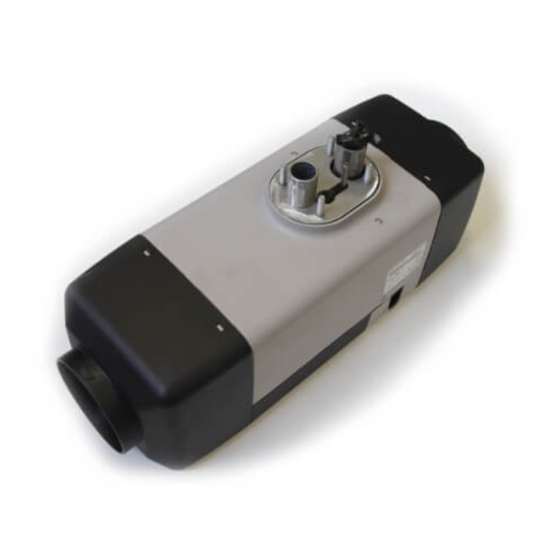
Air Heater
Air Top Evo 3900 / 5500 B (Gasoline)
Air Top Evo 3900 / 5500 D (Diesel)
Installation Manual
WARNING!
– Improper installation or repair of Webasto heating and cooling systems can cause fire
– Installation and repair of Webasto heating and cooling systems requires special
– NEVER attempt to install or repair a Webasto heating or cooling system unless you
– ALWAYS carefully follow Webasto installation and repair instructions and heed all
– Webasto rejects any liability for problems and damage caused by the system being
– Improper installation or installation by untrained personnel voids all warranties on
or the leakage of deadly carbon monoxide leading to serious injury or death.
Webasto training, technical information, special tools and special equipment.
have successfully completed the factory training course and have the technical skills,
technical information, tools and equipment required to properly complete the
necessary procedures.
WARNINGS.
installed by untrained personnel.
this product.
Advertisement
Table of Contents

Related Manuals for Webasto Air Top Evo 3900


Summary of Contents for Webasto Air Top Evo 3900
-
Page 1: Installation Manual
– Installation and repair of Webasto heating and cooling systems requires special Webasto training, technical information, special tools and special equipment. – NEVER attempt to install or repair a Webasto heating or cooling system unless you have successfully completed the factory training course and have the technical skills, technical information, tools and equipment required to properly complete the necessary procedures. -
Page 3: Table Of Contents
4.2 Air Top EVO 3900/5500 Installation Situation ........ - Page 4 14.3 Fuel for Air Top EVO 3900/5500 D (Diesel/Heating Oil): .......
-
Page 5: Safety And General Information
General Information Webasto Product North America, Inc. is pleased to provide this installation manual with the AT 3900/5500 air heater. When installed according to the guidelines stated in this manual, you can expect your customer to enjoy many years of trouble-free heater operation. -
Page 6: Regulation For Installation In The Vehicle
Failure to comply with all installation instructions is a misuse of Webasto products. The same applies for repairs without using genuine Webasto service parts. This will void the heaters “official Marks of Conformity.”... -
Page 7: Exhaust System
When the engine stops, the heating system must cut out automatically and the fuel supply must be stopped within 5 seconds. The heating system may remain in operation if a manual unit has already been activated. www.webasto.us Webasto Thermo & Comfort N.A., Inc. -
Page 8: Purpose Of The Air Heater
Purpose of the Air Heater Air Top Evo 3900/5500 Purpose of the Air Heater The Webasto Air Top EVO 3900/5500 air heaters are designed – to heat cabins, boats (Diesel Only), trucks, minibuses, vans and motor homes – to defrost vehicle windows –... -
Page 9: Installation
• 1/2 Heavy-Duty, low speed drill with good quality, sharp drill bits and a selection of hole saws. • Mounting/ Drilling Templates. Air Top EVO 3900/5500 Installation Situation NOTE: Check the installation situation of the relevant vehicle type. Installation Location The heater may be fitted both in the interior or on the exterior of the vehicle. -
Page 10: To Install The Heater
A seal (Figure 4) must be fitted between the heater and the vehicle body. This seal must be replaced each time the heater is installed. The support area for the heater foot must be flat. A special tools can be purchased from Webasto to drill the holes and, if necessary, smooth the support area. -
Page 11: Optional Mounting Plate
The model/serial number plate of the heater must be positioned so that it cannot be damaged and must be clearly legible when the heater is installed (otherwise a duplicate model plate must be used). Inapplicable years must be erased from the model plate. www.webasto.us Webasto Thermo & Comfort N.A., Inc. -
Page 12: Installation Example
Installation Air Top Evo 3900/5500 Installation Example Figure 7. Installation example with heater in stalled under-bunk. (Recirculation mode) Webasto Thermo & Comfort N.A., Inc. www.techwebasto.com... -
Page 13: Hot Air System
The internal diameter of the main section of the hot air line should be: 90 mm (3.54 in.) minimum for the Air Top EVO 5500 80 mm (3.14 in.) minimum for the Air Top EVO 3900 NOTE: Only materials that can permanently withstand temperatures of at least 130°C (266°F) may be used for the hot air line. -
Page 14: External Temperature Sensor
– by close to heat sources (for example the vehicle’s own heating system). – be placed in direct sunlight (for example on the dashboard). – be installed behind curtains or the like. External temperature sensor Cover Figure 10. External temperature sensor - optional Webasto Thermo & Comfort N.A., Inc. www.techwebasto.com... -
Page 15: Fuel Supply
Vehicles with a Carburetor Equipped Engine The fuel may only be extracted using the special Webasto fuel extractor (see Figure 12) as close to the tank as possible. The connection may be made in either the supply or return line, in which case the return line must lead almost to the base of the tank (see Figure 13). -
Page 16: Vehicles With Fuel Injection Engines
(see Figure 12), in which case it must be ensured that the return line continues almost to the bottom of the tank (see Figure 13 for details of the minimum distance from the bottom of the tank). If this is not the case Webasto fuel extractors or standpipes (see Figures 13, 14 and 15) may be used. -
Page 17: Fuel Metering Pump
Figure 16. Fuel line / coupler hose connection e 17. Fuel Metering Pump DP 2 Fuel Metering Pump Air Top EVO 3900/5500 12 and 24 Volt - Diesel The fuel metering pump is a combined delivery, metering and shut-off system and is subject to certain installation criteria (see Figures 11 and 18). -
Page 18: Fuel Filter
The metering pump must be secured with a vibration-damping mounting. Its installation position is limited as shown in Figure 18 in order to ensure effective automatic bleeding. As a result of the risk of corrosion, only genuine Webasto parts may be used for the plug connections between the metering pump and the metering pump wiring harness. -
Page 19: Combustion Air Supply
Do not use an exhaust line as the combustion air line since otherwise the metering pump cable from the combustion air inlet port may be damaged. The combustion air opening must not be under the minimum water drive-through level permitted for the vehicle. See the regulations for the installation for further regulations. www.webasto.us Webasto Thermo & Comfort N.A., Inc. -
Page 20: Exhaust Pipe
The exhaust muffler should ideally be installed near the heater. The heater may also be operated without a muffler. Ø 0-90° 0-90° Figure 20. Exhaust muffler - exhaust flow is non-directional (arbitrary) Webasto Thermo & Comfort N.A., Inc. www.techwebasto.com... -
Page 21: Combustion Air Inlet And Exhaust Lines
Discharge direction almost vertical 90° ± 10° Exhaust line: max. 270°. Figure 24. Exhaust pipe opening IMPORTANT! If the exhaust pipe ends other than as shown in Figure 24, it will pose a fire risk. www.webasto.us Webasto Thermo & Comfort N.A., Inc. -
Page 22: Electrical Connections
Figure 26. Fuse holder - weather sealed IMPORTANT! The Air Top EVO 3900/5500 requires 6.25 amps @ 12 volts or 12.5 amps @ 24 volts during start-up. The main power connection has to be made at a circuit designed to sustain this load without voltage drop. -
Page 23: Control Element (Rheostat)
(see page12). See installation instructions included with the sensor or see the service instructions in the Workshop manual for further information. Cover Figure 30. External temperature sensor - optional www.webasto.us Webasto Thermo & Comfort N.A., Inc. -
Page 24: Control Element (Smartemp)
– Ensure good readability when selecting installation location. – Observe information on adhesive labels and colored markings when connecting the control element to vehicles wiring harness. Figure 32. SmarTemp drilling dimensions Webasto Thermo & Comfort N.A., Inc. www.techwebasto.com... -
Page 25: Control Element (Mc04/05)
– Ensure good readability when selecting installation location – Observe information on adhesive labels and colored markings when connecting Control Panel to vehicle wiring harness Figure 35. Installing control element MC04/05 www.webasto.us Webasto Thermo & Comfort N.A., Inc. - Page 26 Optional connection for: - Telestart/Thermo Call - Webasto Thermo Test Diagnose Heater units wiring harness Figure 35. Connection diagram for Air Top EVO 3900/5500 with control element MC04/05 Control Element (1531 Combi Timer) 10.5.1 Combination Timer 1531 Black Battery Positive...
-
Page 27: Circuit Diagrams
Plug connector, 4-pin x3 (a,b,c) To item S Plug connector, 2-pin Plug connector, 2-pin To item Y1 12-pin plug connection To item P Plug connector, 8-pin Plug connector, 8-pin Metering pump Solenoid valve for pumping device www.webasto.us Webasto Thermo & Comfort N.A., Inc. - Page 28 Circuit Diagrams Air Top Evo 3900/5500 Figure 37. Standard wiring diagram for the Air Top EVO 3900/5500, 12 / 24 Volt with control element (Rheostat) Webasto Thermo & Comfort N.A., Inc. www.techwebasto.com...
- Page 29 Air Top Evo 3900/5500 Circuit Diagrams Figure 38. Standard wiring diagram for the Air Top EVO 3900/5500, 12 / 24 Volt with control element (SmarTemp) www.webasto.us Webasto Thermo & Comfort N.A., Inc.
- Page 30 Circuit Diagrams Air Top Evo 3900/5500 Figure 39. Standard wiring diagram for the Air Top EVO 3900/5500, 12 / 24 Volt with control element (MC04/05) Webasto Thermo & Comfort N.A., Inc. www.techwebasto.com...
- Page 31 Air Top Evo 3900/5500 Circuit Diagrams Figure 40. Standard wiring diagram for the Air Top EVO 3900/5500, 12 / 24 Volt with control element (1531 combi timer) www.webasto.us Webasto Thermo & Comfort N.A., Inc.
-
Page 32: Starting The Heater For The First Time
Resetting after a fault cut-out Indicator / Error code display Changes to the settings on the control element are implemented after a delay. Figure 41. Control element (Rheostat) 12.1.2 SmarTemp Control Figure 42. Control element (SmarTemp Control) Webasto Thermo & Comfort N.A., Inc. www.techwebasto.com... - Page 33 ). Altitude correction is used when operating the heater in higher than 1,200 m above sea level (not available for MC04 M and MC04 SPM) 12.1.4 1531 Combi Timer Figure 44. Control element (1531 Combi Timer) www.webasto.us Webasto Thermo & Comfort N.A., Inc.
-
Page 34: Fault Lock-Out
Overheating: Resulting in permanent heater fault lock-out F 11 Overheating sensor interrupt or short circuit F 12 Heater lock-out F 13 Heater lock-out permanent F 14 Overheating sensor incorrect position F 15 Set point generator interrupt Webasto Thermo & Comfort N.A., Inc. www.techwebasto.com... -
Page 35: Technical Data
If you change to low-temperature fuel, the heater must be operated for approx. 20 minutes so that the fuel system is filled with the new fuel. The Air Top EVO 3900/5500 heater is also licensed for use with PME (bio-diesel), which complies with DIN EN 14214. Heater... -
Page 36: Version
Version Air Top Evo 3900/5500 15. Version Air Top EVO 3900/5500 B (Gasoline) Air heater for gasoline (12 V) Air Top EVO 3900/5500 D (Diesel) Air heater for Diesel/heating oil (12 or 24 V) Webasto Thermo & Comfort N.A., Inc. -
Page 37: Drilling Template
Air Top Evo 3900/5500 Drilling Template 16. Drilling Template Ø Ø Ø Ø Ø Figure 45. Drilling Template for Heater Installation (Dimensions in millimeters) Figure 46. Drilling Template for MC04/05 Control Panel www.webasto.us Webasto Thermo & Comfort N.A., Inc. - Page 38 Notes Air Top Evo 3900/5500 www.webasto.us Webasto Thermo & Comfort N.A., Inc.
- Page 39 Air Top Evo 3900/5500 Notes www.webasto.us Webasto Thermo & Comfort N.A., Inc.
- Page 40 Webasto Thermo & Comfort N.A., Inc. 15083 North Road Fenton, MI 48430 Technical Assistance Hotline USA: (800) 555-4518 Canada: (800) 667-8900 www.webasto.us Org. 05/2009 Rev. 6/2013 P/N LIT909385B www.techwebasto.com...
Need help?
Do you have a question about the Air Top Evo 3900 and is the answer not in the manual?
Questions and answers