Table of Contents
Advertisement
Quick Links
SERVICE
Color Laser MFP
Refer to the service manual in the GSPN (see the rear cover) for more information.
Color Laser MFP
CLX-8640/8650 series
CLX-8640ND, CLX-8650ND
(Ver1.0)
MANUAL
1. Precautions
2. Product specifications and Description
3. Disassembly and Reassembly
4. Troubleshooting
5. System Diagram
6. Reference Information
Contents
Advertisement
Chapters
Table of Contents
Troubleshooting

Related Manuals for Samsung CLX-8640 series


Summary of Contents for Samsung CLX-8640 series
- Page 1 Color Laser MFP CLX-8640/8650 series CLX-8640ND, CLX-8650ND (Ver1.0) SERVICE MANUAL Color Laser MFP Contents 1. Precautions 2. Product specifications and Description 3. Disassembly and Reassembly 4. Troubleshooting 5. System Diagram 6. Reference Information Refer to the service manual in the GSPN (see the rear cover) for more information.
-
Page 2: Table Of Contents
Imaging Unit ......................2 − 33 2.6.2.1. Imaging Unit Overview .................. 2 − 33 2.6.2.2. Drum drive ....................2 − 34 2.6.2.3. Developer Unit ..................... 2 − 35 2.6.3. ITB (Intermediate Transfer Belt) Unit................2 − 37 Copyright© 1995-2013 SAMSUNG. All rights reserved. - Page 3 2.10.15. Connector PBA ......................2 − 78 2.10.16. Side Joint PBA ......................2 − 78 2.10.17. Finisher IF PBA ......................2 − 79 2.10.18. Paper Size PBA ......................2 − 79 2.10.19. Sensor locations ......................2 − 80 Copyright© 1995-2013 SAMSUNG. All rights reserved.
- Page 4 3.3.17.1. MP Pick Up Unit................... 3 − 26 3.3.17.2. Duplex Exit Sensor..................3 − 29 3.3.17.3. Duplex Motor ....................3 − 30 3.3.17.4. Duplex Fan ....................3 − 30 3.3.18. Exit Unit........................3 − 31 Copyright© 1995-2013 SAMSUNG. All rights reserved.
- Page 5 Troubleshooting ..........................4 − 1 4.1. Control Panel ..........................4 − 1 4.1.1. Introducing the display screen and useful buttons ..............4 − 2 4.2. Understanding the status LED ......................4 − 6 4.3. Updating Firmware ........................4 − 7 Copyright© 1995-2013 SAMSUNG. All rights reserved.
- Page 6 Capture Log ....................4 − 69 4.5.6.7. System Recovery ..................4 − 70 4.5.6.8. TR Control Mode ..................4 − 73 4.5.6.9. User Data Management ................. 4 − 74 4.6. Error Code and Troubleshooting ....................4 − 75 Copyright© 1995-2013 SAMSUNG. All rights reserved.
- Page 7 Image quality problems and solutions ..................4 − 262 4.8. Other errors .......................... 4 − 271 System Diagram..........................5 − 1 Reference Information..........................6 − 1 6.1. Tools for Troubleshooting......................6 − 1 6.2. Glossary...........................6 − 3 Copyright© 1995-2013 SAMSUNG. All rights reserved.
-
Page 8: Precautions
High voltages and lasers inside this product are dangerous. This product should only be serviced by a factory trained service technician. 2) Use only Samsung replacement parts. There are no user serviceable parts inside the product. Do not make any unauthorized changes or additions to the product as these could cause the product to malfunctions and create an electric shocks or fire hazards. -
Page 9: Caution For Safety
Take care not to cut or damage the power cable or plugs when moving the machine. 9) Use caution during thunder or lightning storms. Samsung recommends that this machine be disconnected from the power source when such weather conditions are expected. Do not touch the machine or the power cord if it is still connected to the wall socket in these weather conditions. -
Page 10: Handling Precautions
1.2.4. Assembly and Disassembly precautions 1) Replace parts carefully and always use Samsung parts. Take care to note the exact location of parts and also cable routing before dismantling any part of the machine. Ensure all parts and cables are replaced correctly. Please carry out the following procedures before dismantling the product or replacing any parts. -
Page 11: Disregarding This Warning May Cause Bodily Injury
5) Do not install the printer on a sloping or unstable surface. After installation, double check that the printer is stable. Copyright© 1995-2013 SAMSUNG. All rights reserved. -
Page 12: Esd Precautions
9) Minimize bodily motions when handling unpackaged replacement ESDs. Normal motions, such as the brushing together of clothing fabric and lifting one’s foot from a carpeted floor, can generate static electricity sufficient to damage an ESD. Copyright© 1995-2013 SAMSUNG. All rights reserved. -
Page 13: Product Specifications And Description
2.1. Product Overview • Printing Speed (Mono/Color) CLX-8650 series : Up to 48 ppm in A4 (51 ppm in Letter) • • CLX-8640 series : Up to 38 ppm in A4 (40 ppm in Letter) • Processor • Dual Core 1GHz Memory •... -
Page 14: Specifications
550 x 523 x 776 mm (21.7 x 20.6 x 30.6 inches) Weight 70.4 Kg (155.21 lbs) (with consumables) Reliability & Service Recommended Printing 7,000 sheets/month (60% Color ratio) Volume (AMPV) Max Monthly Duty 200,000 sheets/month Copyright© 1995-2013 SAMSUNG. All rights reserved. -
Page 15: Print
Printer Languages PCL5C, PCL6, PostScript Level3, PDF 1.7 • PCL : 93 scalable, 1 bitmap Fonts • PS : 136 Downloadable Fonts Yes (PCL & PS3 S/W Font) USB Memory Direct Print Jpeg, Tiff, PDF Copyright© 1995-2013 SAMSUNG. All rights reserved. -
Page 16: Controller And Software
N-up printing, Duplex, Quality Color mode (Color, Gray scale) • Windows 2000/XP(include 64bit)/ 2003/ Vista/ 2008/ Win7/ 2008 R2 (64bit WHQL only) English, French, German, Italian, Spanish, Korean, Russian, Brazilian Language Localization Portuguese UPD (SSPD) Copyright© 1995-2013 SAMSUNG. All rights reserved. - Page 17 ■ Interface Item Specification Parallel (IEEE 1284) Type A High-Speed USB 2.0 Host (2 Ports) Type B Hi-Speed USB 2.0 Peripheral (1Port) Wired LAN Ethernet 10/100/1000 Base TX Wireless LAN Foreign Device Interface Optional Copyright© 1995-2013 SAMSUNG. All rights reserved.
-
Page 18: Network Interface
Printer MIB (RFC 3805) SNMP/MIB Access Finisher MIB (RFC 3806) Samsung Private MIB HP Compatibility Yes - Patially SNMP Trap Window Printing (SMB) LPR/LPD Printing Protocols Netware I-Print Netware NDPS Ether Talk Port 9100 Copyright© 1995-2013 SAMSUNG. All rights reserved. - Page 19 Memory to Client Server Copies Duplex Printing Memory to Print Color Mode Setting Autofit Paper Supply Immediate Image Overwrite On-Demand Supported Job Type Print / Scan / Fax Data Encrytion Cryptography Key length 128bit Copyright© 1995-2013 SAMSUNG. All rights reserved.
-
Page 20: Scan
Email, Fax, Fax Group : 100, E-mail Group : 200 Server Searching Address Book Editing Basic Feature Deleting Grouping import, export Mixed Document Scan Preset Delayed Send Scan Setting Job Done notice Job Recall Copyright© 1995-2013 SAMSUNG. All rights reserved. -
Page 21: Copy
DADF: Scan 300 x 300 dpi, Printing 600 x 600 dpi • Original Type Factory Default Color copy mixed mode Auto Color Full Color Color Setting Twin Color Single Color B&W Platen Legal (8.5" x 14") Max. Original Size DADF Legal (8.5" x 14") Copyright© 1995-2013 SAMSUNG. All rights reserved. - Page 22 Collated and Offset (This is collated output and offset without Staple) • Staple (This is staple and Offset) Proof Copy N-Up 2up, 4-up ID Card Copy Yes (Platen only) Poster Copy Clone Copy Other Features Booklet Covers Transparencies Book Copy Interrupt Copy 2-10 Copyright© 1995-2013 SAMSUNG. All rights reserved.
-
Page 23: Fax
On hook Dial Search Yes(Phone Book) Speed Dial 200 locations Group Dial Max. 100 Groups (Max. locations per 1 Group : 200 locations) Telephone Features TAD I/F Tone/Pulse Pause Auto Redial Last Number Redial Copyright© 1995-2013 SAMSUNG. All rights reserved. 2-11... - Page 24 Receiving Tel number LDAP Check the Success or Fail & Error Re-Faxing from memory in case of Sending fax failed Fax Management Re-Faxing in case of failed page. Delete in memory after sending completely 2-12 Copyright© 1995-2013 SAMSUNG. All rights reserved.
- Page 25 Fax, TEL, Ans/Fax Battery Backup HDD Store, 500 jobs Fax Forward to FAX Yes(On/Off), both Sent and Received Fax Forward to e-mail Broadcasting up to 209 locations Cover page Email Fax-to Client HTTP(S) Multi-destination Copyright© 1995-2013 SAMSUNG. All rights reserved. 2-13...
-
Page 26: Paper Handling
• Archive 1: 84 g/m² • Archive 2: 85-110 g/m² • • Archive 3: 111-130 g/m² • Archive 4: 131-220 g/m² • Transparency: 138-146 g/m² Label: 120-150 g/m² • Sensing Paper empty sensor 2-14 Copyright© 1995-2013 SAMSUNG. All rights reserved. - Page 27 Letter, Legal, Oficio, Folio, A4, JIS B5, ISO B5, Executive, A5, Envelope Media sizes Optional Cassette Tray C5, Custom Plain Paper, Thin Paper, Bond, Pre-Printed, Recycled, Envelope, CardStock, Media types Thick, Cotton, Colored, Archive Copyright© 1995-2013 SAMSUNG. All rights reserved. 2-15...
- Page 28 Output Full sensing: Yes Cartridge Empty Detect : Yes Supporting Throughput 85% from Cassette, 30% from MP tray Automatic Duplex Media sizes 148.5 x 210 mm - 215.9 x 355.6 mm Media types Plain/Thick Paper Media weight 60 to 163 g/m² 2-16 Copyright© 1995-2013 SAMSUNG. All rights reserved.
-
Page 29: Consumables
20,000 standard pages Drum Unit Black CLT-R659K 40,000 pages (3 sheets/job) Yellow CLT-R659Y 40,000 pages (3 sheets/job) Magenta CLT-R659M 40,000 pages (3 sheets/job) Cyan CLT-R659C 40,000 pages (3 sheets/job) Waste Toner Container CLT-W659 20,000 pages Copyright© 1995-2013 SAMSUNG. All rights reserved. 2-17... -
Page 30: Maintenance Parts
Pick up/ Reverse/ Forward roller (Tray JC93-00616A 150,000 impressions 1,2,3,4) DADF Pick-Up roller Assy JC97-04098A 150,000 impressions DADF Retard roller Assy JC97-04135A 150,000 impressions NOTE Depending on the print patterns and job mode used, the lifespan may differ. 2-18 Copyright© 1995-2013 SAMSUNG. All rights reserved. -
Page 31: Options
Second Cassette Feeder CLX-DSK20M/SEE with stand Triple Cassette Feeder CLX-S8640T/SEE 2bin-Finisher CLX-FIN25S/SEE CLX-FAX170/XXX NOTE Fax kit XXX : SEE, XEE, XEG, XEU FDI (Foreign Device SCX-KIT20F/SEE Interface) kit Staple Cartridge SCX-STP000/SEE Card Reader Cover JC95–01835B Copyright© 1995-2013 SAMSUNG. All rights reserved. 2-19... -
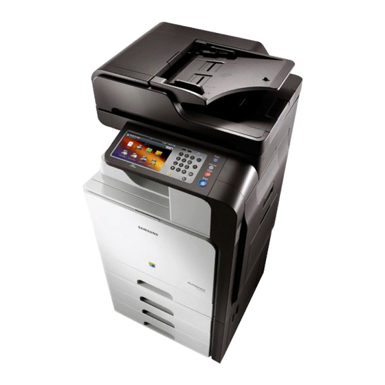
Page 32: System Configuration
Multi-purpose tray paper width guide Triple Cassette Feeder right bottom door Multi-purpose tray support Standard tray (Tray 1) Second Cassette Feeder with stand Triple Cassette Feeder (Tray2, Tray3, Tray4) Standard tray (Tray 1) 2-20 Copyright© 1995-2013 SAMSUNG. All rights reserved. - Page 33 2. Product specifications and Description 2) Inner view Toner cartridges Waste toner container LSU window cleaning stick Imaging units cover Imaging units 3) Rear View Copyright© 1995-2013 SAMSUNG. All rights reserved. 2-21...
- Page 34 Dummy for FDI (Foreign Device Interface) Power-switch Power receptacle View with Standard 2Bin Finisher (optional) Standard 2Bin Finisher Finishing tray Top tray Standard 2Bin Finisher front door Standard 2Bin Finisher front door handle Staple 2-22 Copyright© 1995-2013 SAMSUNG. All rights reserved.
-
Page 35: System Layout
Toner Cartridge 2nd Transfer Roller Unit ITB (Intermediate Transfer Belt) Unit Fuser Unit Drum Unit Exit Unit Developer Unit Scanner (Platen Unit) LSU (Laser Scanning Unit) DADF output tray 1st Tray DADF input tray Copyright© 1995-2013 SAMSUNG. All rights reserved. 2-23... -
Page 36: Paper Path
2. Product specifications and Description Paper Path 2-24 Copyright© 1995-2013 SAMSUNG. All rights reserved. -
Page 37: Feeding System
▪ Plain paper : A5, A4, B5, Letter, Statement, Legal ▪ Special Paper : C5 Weight : plain paper 60~163 g/m² Plate knock up lift type : Lift Motor + Up Limit Sensor Copyright© 1995-2013 SAMSUNG. All rights reserved. 2-25... -
Page 38: Pick-Up Unit
The reverse roller serves to make sure that a single sheet of paper to the feed roller. The shaft of the reverse roller is driven by gear in the opposite direction of the paper path. 2-26 Copyright© 1995-2013 SAMSUNG. All rights reserved. -
Page 39: Registration Unit
Side Margin : 4.23 ± 1.5 mm ( Tray3, 4, 5 : 4.23 ± 2.0 mm ) • Duplex Top Margin : 4.23 ± 2.0 mm • Duplex Side Margin : 4.23 ± 2.0 mm Copyright© 1995-2013 SAMSUNG. All rights reserved. 2-27... -
Page 40: Mpf(Multi-Purpose Feeder) Unit
Capacity : 100 sheets (80g/m² paper standard) • Media Size : Max 8.5” ×14” / Min 3.87”×5.8” • Media Weight : Plain paper 60 ~ 220 g/m² • Feeding Speed : 46 ppm (Letter) 2-28 Copyright© 1995-2013 SAMSUNG. All rights reserved. -
Page 41: Exit Unit
The Exit Unit sends the transferred paper from the fuser unit to the exit tray. In case of duplex printing mode, the Invert gate is down to rotates the return roller in reverse and the paper is transferred to the duplex unit. Copyright© 1995-2013 SAMSUNG. All rights reserved. 2-29... -
Page 42: Duplex Unit
2. Product specifications and Description 2.4.6. Duplex Unit Duplex Unit receives the paper from exit unit and sends it to transfer unit again. 2-30 Copyright© 1995-2013 SAMSUNG. All rights reserved. -
Page 43: Fuser Unit
NC sensor malfunction. These thermostats are used to prevent abnormal operation. When the thermostat is triggered, it must be replaced (as well as the other damaged parts in the fuser unit). Copyright© 1995-2013 SAMSUNG. All rights reserved. 2-31... -
Page 44: Image Creation
7) Cleaning and quenching for transfer belt : The cleaning brush and blade clean the belt surface. The grounding roller inside the transfer belt unit removes the remaining charge on the belt. 2-32 Copyright© 1995-2013 SAMSUNG. All rights reserved. -
Page 45: Imaging Unit
The developing gap between a drum and the corresponding magnetic roller cannot be adjusted. The ID chip is the sub part of the Drum unit. It stores the count information and several data. Copyright© 1995-2013 SAMSUNG. All rights reserved. 2-33... -
Page 46: Drum Drive
The BLDC motor maintains the constant speed. So, the speed sync for each color depends on the BLDC motor without the additional device. Phase sync for each OPC runout prints the pattern on the ITB and is adjusted by the data automatically. 2-34 Copyright© 1995-2013 SAMSUNG. All rights reserved. -
Page 47: Developer Unit
Each Developer unit has a TC(Toner Carrier) sensor[C]. They are used for controlling the operating range of toner density. Drum Unit has the CRUM that stores the information for corresponding the Drum unit. Copyright© 1995-2013 SAMSUNG. All rights reserved. 2-35... - Page 48 During development job If the developer unit is stored at temperature above 50°C (122°F), it does not works normally. The toner in developer unit is easy to harden at temperature above 50°C (122°F). 2-36 Copyright© 1995-2013 SAMSUNG. All rights reserved.
-
Page 49: Itb (Intermediate Transfer Belt) Unit
One photo sensor controls the position of the first transfer roller. ITB (Intermediate Transfer Belt) 1st Transfer Roller ITB Drive Roller Tension Roller Photo Sensor Cleaning Blade ACR Sensor 2nd Transfer Roller Auger (Toner collection Auger) Drum Unit Copyright© 1995-2013 SAMSUNG. All rights reserved. 2-37... -
Page 50: Transfer Belt Drive
2. Product specifications and Description 2.6.3.2. Transfer belt drive The ITB drive motor[A] drives the transfer belt[B] by using gears and the ITB drive roller[C]. 2-38 Copyright© 1995-2013 SAMSUNG. All rights reserved. -
Page 51: Transfer Belt Cleaning
The film[D] on the ITB cleaner protects against toner contamination. The driving power by driver roller is transferred to the tension roller[E] and the toner collection auger gear[G] drives the gear[F], and collects the toner. Copyright© 1995-2013 SAMSUNG. All rights reserved. 2-39... -
Page 52: Laser Scanning Unit (Lsu)
This LSU adopted the cross scan type scanning. K Color and C Color scan the laser beam from the rear to the front, M Color and Y Color scan the laser beam from the front to the rear. PBA-LSU LD Motor Polygon Lens-Ftheta A Lens-Ftheta B PBA-LSU PD 2-40 Copyright© 1995-2013 SAMSUNG. All rights reserved. -
Page 53: Laser Scanning Optical Path
Laser Diode : Single Beam driving IC : for Dual LD Polygon Motor 36,064.9 rpm Process speed 305.35 mm/sec H/W interface Interface with machine : • FFC : 60 pin Pressure welding type 8 pin • Copyright© 1995-2013 SAMSUNG. All rights reserved. 2-41... -
Page 54: Laser Synchronizing Detectors
Hsync. The arrow in the above diagram shows the data scanning direction for each color. Black (& Cyan) and Yellow (& Magenta) use the same polygon motor scanning in opposite directions. 2-42 Copyright© 1995-2013 SAMSUNG. All rights reserved. -
Page 55: Drive System
The following diagram displays the locations of the printer drive motors. Motor Motor type Function OPC / DEVE BLDC OPC/DEVE driving BLDC ITB driving T1 Dis/En PM-STEP T1 Dis/Engage BLDC Regi / MP / Feed / Pick-up driving E-CLT Pick-up driving control Copyright© 1995-2013 SAMSUNG. All rights reserved. 2-43... - Page 56 Fuser Mode driving control Cst Lift Cst Lift driving Toner Supply Toner transfer in toner cartridge driving Duct PM-STEP Waste toner container leveling ITB Auger PM-STEP Waste toner transfer in ITB Shutter-ACR ACR Open/Close 2-44 Copyright© 1995-2013 SAMSUNG. All rights reserved.
-
Page 57: Main Drive Unit (Opc, Deve, Itb, T1 Dis_Eng)
2. Product specifications and Description 2.8.2. Main Drive Unit (OPC, DEVE, ITB, T1 DIS_ENG) Front View Rear View Copyright© 1995-2013 SAMSUNG. All rights reserved. 2-45... -
Page 58: Ph(Paper Handling) Drive
1 BLDC → 2 Gear → 6 Gear (MP driving) • 1 BLDC → 7 Gear → 8 Gear (Feed driving) • • 1 BLDC → 7 Gear → 8 Gear → 9 Clutch/Gear (Pick up driving) 2-46 Copyright© 1995-2013 SAMSUNG. All rights reserved. -
Page 59: Fuser_Exit Drive
• 1 BLDC → 2 Gear (Fuser driving) • 1 BLDC → 3 Gear → 4 Gear (Exit driving) 5 DC → 6 Gear → 7 Gear → 8 Gear (Mode driving) • Copyright© 1995-2013 SAMSUNG. All rights reserved. 2-47... -
Page 60: Cst Lift Drive
Duct & Cartridge driving 1 DC → 2 Gear → 3 Gear → 4 Gear (Toner Cartridge Auger driving) • 1 DC → 2 Gear → 3 Gear → 5 Gear (Duct Auger driving) • 2-48 Copyright© 1995-2013 SAMSUNG. All rights reserved. -
Page 61: Waste Toner Container Drive
1 PM Step → 2 Gear-RDCN WTB • 2.8.8. ITB Auger Drive The following is a diagram of the ITB Auger drive: Power Train ITB Auger driving 1 PM Step → 2 Gear → 3 Gear • Copyright© 1995-2013 SAMSUNG. All rights reserved. 2-49... -
Page 62: Duplex Automatic Document Feeder(Dadf)
Feeds an original before simplex scanning. White-Bar Supports a stable scanning. Duplex Scan roller Feeds an original before duplex scanning. Duplex CCDM Scans a back page of original. Feed-Out roller Transfers a scanned original to the exit tray. 2-50 Copyright© 1995-2013 SAMSUNG. All rights reserved. -
Page 63: Electrical Parts Location
2. Product specifications and Description 2.9.2. Electrical parts location Copyright© 1995-2013 SAMSUNG. All rights reserved. 2-51... - Page 64 ADF-PBA PHOTO-INTERRUPTER(PAPER-WIDTH) 0604-001415 ADF-PBA PHOTO-INTERRUPTER(PICK-UP) 0604-001415 ADF-PBA PHOTO-INTERRUPTER(PAPER-DETECT) 0604-001415 ADF-PBA PHOTO-INTERRUPTER(PAPER-FEED) 0604-001415 ADF-PBA PHOTO-INTERRUPTER(REGI) 0604-001415 ADF-PBA PHOTO-INTERRUPTER(SIMPLEX SCAN) 0604-001381 ADF-PBA PHOTO-INTERRUPTER(DUPLEX SCAN) 0604-001381 ADF-PBA PHOTO-INTERRUPTER(FEED-OUT) 0604-001415 ADF-PBA PHOTO-INTERRUPTER(PAPER-LENGTH) 0604-001415 ADF-PBA DUAL-CCDM PBA JC92-02537A 2-52 Copyright© 1995-2013 SAMSUNG. All rights reserved.
-
Page 65: Dadf Drive System
1) Checks a paper detection. 2) Checks the original width size. 3) Holds the original not to be moved in paper path before pick up driving. 4) Starts pick up driving. 5) Separates an original. Copyright© 1995-2013 SAMSUNG. All rights reserved. 2-53... - Page 66 2) When original passes the simplex scan actuator, simplex scan starts. White-Bar functions to prevent the wrinkle. 3) When original passes the duplex scan actuator, duplex scan starts. 4) Original is transferred to exit tray. 2-54 Copyright© 1995-2013 SAMSUNG. All rights reserved.
-
Page 67: Hardware Configuration
I2C to check their life. The main controller adopted Dure Core CPU 1GHZ, DDR3 1GB memory, Flash NAND 128MB, 320GB SATA HDD to control the engine driving, video signal processing, interface, etc. successfully. Copyright© 1995-2013 SAMSUNG. All rights reserved. 2-55... - Page 68 The HVPS board generates high-voltage channels and controls it. The FDB board controls the fuser lamp On/Off. The SMPS board generates the 5V, 24V for system power. 2-56 Copyright© 1995-2013 SAMSUNG. All rights reserved.
- Page 69 2. Product specifications and Description Circuit Board Locations The following diagrams show the locations of the printer circuit boards: Copyright© 1995-2013 SAMSUNG. All rights reserved. 2-57...
-
Page 70: Main Controller
1Gb p s N/W RGMII CLUTCH HP VC S OLENOID Real Time Co n tro l ENS ORS can /En g in e/Fax NAND DDR3 320GB HVP S LS U 128MB 2.5” Lin u x 2-58 Copyright© 1995-2013 SAMSUNG. All rights reserved. - Page 71 HVPS1 USB HOST JACK SODIMM IF FDB IF USB DEVICE JACK • Information Part Code : JC92–02516A NOTE This main board is for all models of the CLX-8640/8650 series Part Name : PBA-MAIN Copyright© 1995-2013 SAMSUNG. All rights reserved. 2-59...
- Page 72 The FAX JOINT PBA is used for interfacing between the main board and modem PBA. It uses UART for interface. • Information Part Code : JC92-02439A Part Name : PBA-FAX JOINT • Connection Main PBA I/F connector Modem Card I/F connector 2-60 Copyright© 1995-2013 SAMSUNG. All rights reserved.
- Page 73 The FDI Module as a option is used to track machine usage such as the number of print or copy pages for some special users. This module interfaces to the main board. • Information Part Code : JC92-01616A PBA name : PBA-SUB FDI • Connection Connector to Main controller Copyright© 1995-2013 SAMSUNG. All rights reserved. 2-61...
-
Page 74: Ope Controller
7 inch touch LCD(800x480). The AM3715 is used to interface with users through the touch screen and some buttons. The AM3715 is based on Android OS and supports the Graphic Accelation for better UI. 1) OPE controller diagram 2-62 Copyright© 1995-2013 SAMSUNG. All rights reserved. - Page 75 • Connection KEY PBA Interface connector MAIN PBA POWER Interface connector LCD DATA Interface connector MAIN PBA USB Interface connector LCD TSP Interface LCD BACK LIGHT Interface USB Host Port for Memory Stick Copyright© 1995-2013 SAMSUNG. All rights reserved. 2-63...
- Page 76 Information Part Code : JC07–00021A Part Name : LCD/TSP 4) OPE KEY PBA • Information Part Code : JC92–02435A Part Name : OPE KEY • Connection Interface Connector to OPE Main Magnetic Buzzer 2-64 Copyright© 1995-2013 SAMSUNG. All rights reserved.
-
Page 77: Adf Pba
PAPER DET1,2 / FEED,PICKUP ROLLER DET/ FEED DET SENSOR EXIT SENSOR COVER OPEN SENSOR / FAN I/F PAPER LENGTH SENSOR PAPER REGI SENSOR PICKUP,FEED MOTOR / CLUTCH SCAN I/F PBA SCAN READ1,2 SENSOR Copyright© 1995-2013 SAMSUNG. All rights reserved. 2-65... - Page 78 • Information Part Code : JC92-02518A PBA Name : PBA-SCAN I/F • Connection MAIN PBA I/F APS SENSOR PBA I/F COVER OPEN SENSOR SCAN MOTOR SCAN FAN CCD HOME SENSOR ADF PBA I/F 2-66 Copyright© 1995-2013 SAMSUNG. All rights reserved.
- Page 79 LVDS format with serialization. This board handles all the conversion of an image reflected from the platen glass. • Information Part Code : JC92-02536A PBA Name : PBA-CCDM PLATEN • Connection PBA-SCAN IF Copyright© 1995-2013 SAMSUNG. All rights reserved. 2-67...
- Page 80 The WLED AL FRONT consists of two White-LED used as scanner light. The ADF CCDM and PLATEN CCDM uses it each. • Information Part Code : JC92-02538A PBA Name : PBA-WLED AL FRONT • Connection PBA-CCDM PLATEN PBA-CCDM ADF 2-68 Copyright© 1995-2013 SAMSUNG. All rights reserved.
-
Page 81: Tcf(Triple Cassette Feeder) Pba
Stpe Motor1 / Feed Clutch1 / Pick Up Clutch1 Empty Sensor 2,3 / Lift Limit Sensor 2,3 / Feed Sensor 2,3 Step Motor 2,3 Feed Clutch 2 / Pick Up Clutch 2,3 BLDC motor / Side Cover Open Size Sensor 2,3 Copyright© 1995-2013 SAMSUNG. All rights reserved. 2-69... -
Page 82: Smps Board
• Information 110V 220V Part Code JC44-00149B JC44-00150B Part Name SMPS Type 6 V1 SMPS Type 6 V2 • Connection INPUT_AC OUTPUT_24V1/2/3/4/5/6 (to DC POWER PBA) SMPS Enable OUTPUT_5V1/2/3/4 (to DC POWER PBA) 2-70 Copyright© 1995-2013 SAMSUNG. All rights reserved. - Page 83 5V Ground +5V2 Power 5V Ground +5V3 Power 5V Ground +5V4 Power 5V Ground Signal Connector (CN4) PIN Assign PIN Name Description RS24V 24V Remote Sense 24V_ON_OFF 24V _ON_OFF RS5V 5V Remote Sense Copyright© 1995-2013 SAMSUNG. All rights reserved. 2-71...
-
Page 84: Fuser Drive Board (Fdb)
This board supplies the voltage to Fuser AC, Heater, Main board. • Information 110V 220V SEC CODE JC44-00210A JC44-00211A PBA NAME FDB V1 FDB V2 • Connection Heater I/F Fuser AC FDB I/F Type 6 Main S/W Inlet Heater S/W 2-72 Copyright© 1995-2013 SAMSUNG. All rights reserved. -
Page 85: Hvps Board
Part Code : JC44–00220A Part Name : HVPS • Connection DEV - K DEV - C DEV - M DEV - Y MHV - K MHV - C MHV - M MHV - Y MAIN I/F Copyright© 1995-2013 SAMSUNG. All rights reserved. 2-73... - Page 86 HVPS board2 generates 7 high-voltage channels, which include THV1(4), THV2(+/-), SAW. • Information Part Code : JC44–00221A Part Name : HVPS • Connection THV1 - K THV1- C THV1- M THV1 - Y THV2 (+) / (-) Saw Bias MAIN I/F 2-74 Copyright© 1995-2013 SAMSUNG. All rights reserved.
-
Page 87: Eraser Pba
2.10.9. Fuser PBA For counting the fuser unit life cycle, the Fuser PBA detects that the fuser unit is new or not. • Information Part Code : JC92-02514A Part Name : FUSER PBA Copyright© 1995-2013 SAMSUNG. All rights reserved. 2-75... -
Page 88: Crum Pba
2.10.12. Toner CRUM Joint PBA The Toner CRUM Joint PBA is the interface PBA between the toner cartridge and the machine. • Information Part Code : JC92–02456A • Part Name : PBA-TONER CRUM • 2-76 Copyright© 1995-2013 SAMSUNG. All rights reserved. -
Page 89: Itb Encoder Pba
ITB Engage Home Sensor 2.10.14. Toner Connector PBA This board is connected to the TC sensor inside developer unit and waste toner sensor. • Information Part Code : JC92–02513A Part Name : TONER_CONNECTOR Copyright© 1995-2013 SAMSUNG. All rights reserved. 2-77... -
Page 90: Connector Pba
Part Name : CONNECTOR • 2.10.16. Side Joint PBA The Side Joint PBA is the interface PBA for sensor signal in the side cover. • Information • Part Code : JC92–02515A • Part Name : SIDE_JOINT 2-78 Copyright© 1995-2013 SAMSUNG. All rights reserved. -
Page 91: Finisher If Pba
Part Name : FINISHER_IF • 2.10.18. Paper Size PBA The Paper Size PBA detect the paper size in the cassette. • Information • Part Code : JC32–00013B Part Name : SENSOR-PAPER SIZE • Copyright© 1995-2013 SAMSUNG. All rights reserved. 2-79... -
Page 92: Sensor Locations
2. Product specifications and Description 2.10.19. Sensor locations The following image shows the sensor locations of this machine. 2-80 Copyright© 1995-2013 SAMSUNG. All rights reserved. - Page 93 CST EMPTY 0604-001415 PICKUP LEVEL 0604-001415 DPX JAM 0604-001415 DPX READY 0604-001415 MP EMPTY 0604-001415 WIDTH 0604-001415 ITB CAM 0604-001415 THERMISTOR-NTC ASSY 1404-001417 SENSOR-CTD JC32-00012A AUTOSIZE_SENSOR JC32-00013B CTD-SENSOR JC32-00014A SENSOR HUMIDITY JC32-00015A SENSOR-DEVELOPER JC32-00016A Copyright© 1995-2013 SAMSUNG. All rights reserved. 2-81...
- Page 94 2. Product specifications and Description Symbol Sensor Part Code Controller Board CAM-ACR CHECK 0604-001415 2-82 Copyright© 1995-2013 SAMSUNG. All rights reserved.
-
Page 95: Disassembly And Reassembly
3.1.1. Precautions when assembling and disassembling • Use only approved Samsung spare parts. Ensure that part number, product name, any voltage, current or temperature rating are correct. Failure to do so could result in damage to the machine, circuit overload, fire or electric shock. -
Page 96: Releasing Plastic Latches
Many of the parts are held in place with plastic latches. The latches break easily; release them carefully. To remove such parts, press the hook end of the latch away from the part to which it is latched. Copyright© 1995-2013 SAMSUNG. All rights reserved. -
Page 97: Replacing The Maintenance Part
3.2.1. Drum Unit 1. Open the front cover. Remove the waste toner 3. Open the drum unit cover by pulling down the green container[A]. lever. 2. Open the side cover. 4. Remove the drum unit. Copyright© 1995-2013 SAMSUNG. All rights reserved. -
Page 98: Developer Unit
And then release the toner supply cap. 2. Remove the corresponding drum unit. (Refer to 3.2.1) 3. Remove the developer unit cover[A]. 4. Pull down the toner supply shutter. 6. Remove the bracket[B] after removing 1 screw. Copyright© 1995-2013 SAMSUNG. All rights reserved. - Page 99 3. Disassembly and Reassembly 7. Remove the developer unit after unplugging the 8. Install the new developer unit. connector. 9. Turn the machine on while opening the front cover. 10. After machine initialization, close the front cover. Copyright© 1995-2013 SAMSUNG. All rights reserved.
-
Page 100: Itb Unit
2. Open the side cover. 6. When you see the lever, push it then take off the ITB 3. Release the both stopper to link the side unit. unit. 4. Pull the holder to the direction of arrow. Copyright© 1995-2013 SAMSUNG. All rights reserved. -
Page 101: Fuser Unit
2. Open the side cover. 4. Install the new transfer roller Assy. 5. Turn the machine on while opening the side cover. 6. After machine initialization, close the side cover. Copyright© 1995-2013 SAMSUNG. All rights reserved. -
Page 102: Pick-Up_Reverse_Forward Roller
3. Lift small tap, remove the pick up / reverse/ forward roller. 2. Remove the cassette while pushing the both sides linkers. NOTE When replacing these rollers, it is recommended that you replace all three rollers at the same time. Copyright© 1995-2013 SAMSUNG. All rights reserved. -
Page 103: Dadf Pick-Up Roller Assy
3. Disassembly and Reassembly 3.2.7. DADF Pick-up roller Assy 1. Open the DADF-open cover. 2. Open up the HOLDER PICK-UP. 3. Release the DADF pick-up roller Assy by pulling the shaft to the direction of arrow. Copyright© 1995-2013 SAMSUNG. All rights reserved. -
Page 104: Dadf Reverse Roller Assy
2. Remove the TRAY-MP MAIN from the attachment the projection of TRAY-MP MAIN. hole of LEVER-MP FRONT and LEVER-MP REAR. (Unite the convex part of an axis, and the concave portion of a hole) 3-10 Copyright© 1995-2013 SAMSUNG. All rights reserved. - Page 105 3. Release the metal PIN connected with the main part. 5. Remove 5 screws of BRACKET-R COVER RIGHT. Separate the RIGHT COVER. 4. Remove screw of BRACKET-DUP MAIN F to GUIDE-PUSHER DEVE F. 6. Remove 3 screws of BRACKET-F COVER RIGHT. Copyright© 1995-2013 SAMSUNG. All rights reserved. 3-11...
- Page 106 7. Remove 8 screws. Separate the DUPLEX from the 9. Remove 2 screws. Separate the MP from the DUPLEX. COVER RIGHT. 10. Remove 4 screws. Separate the MP-LOWER GUIDE from the MP-UPPER GUIDE. 8. Unplug the connector. 3-12 Copyright© 1995-2013 SAMSUNG. All rights reserved.
- Page 107 11. Remove the RING-E. Remove the MP-PICK UP from 13. Remove the HOUSING-RETARD MP from the the HOLDER-MP ROLLER. GUIDE-BASE MP. 14. Remove the RETARD ASSY from the HOUSING-RETARD MP. 12. Extract the MP PICKUP SHAFT. Remove the MP-PICK UP RUBBER. Copyright© 1995-2013 SAMSUNG. All rights reserved. 3-13...
- Page 108 3. Disassembly and Reassembly 15. Remove the MP-PICK UP RETARD. 3-14 Copyright© 1995-2013 SAMSUNG. All rights reserved.
-
Page 109: Replacing The Main Svc Part
3.3. Replacing the main SVC part 3.3.1. Left Cover 1. Remove the COVER-LEFT TOP[A]. 2. Remove the left cover after removing 8 screws. 3.3.2. Rear Cover 1. Remove the rear cover after removing 7 screws. Copyright© 1995-2013 SAMSUNG. All rights reserved. 3-15... -
Page 110: Hvps
1. Remove the rear cover. (Refer to 3.3.2) 3. Unplug all connectors on HVPS board2. Remove 4 screws. And remove the HVPS board2. 2. Unplug all connectors on main board. Remove 4 screws. And remove the main board shield. 3-16 Copyright© 1995-2013 SAMSUNG. All rights reserved. -
Page 111: Temperature Sensor
3. Open the front cover. Remove 3 screws. And remove the ITB Waste Auger Drive Unit. 2. Remove 3 screws. Remove the HVPS board1 with its holder. Unplug the connector from the ITB Waste Auger Drive Unit.. Copyright© 1995-2013 SAMSUNG. All rights reserved. 3-17... -
Page 112: Lsu
And remove the HVPS board1 holder. 3. Remove 2 screws. Take off the LSU slowly. NOTE If you yank the LSU, the LSU harness may be damaged. 4. Unplug the LSU harness from the left. Remove the LSU. 3-18 Copyright© 1995-2013 SAMSUNG. All rights reserved. -
Page 113: Main Board
When replacing the engine board, you must insert the MSOK and Memory on new engine board. 3.3.8. SMPS board 1. Remove the rear cover. (Refer to 3.3.2) 2. Unplug all connectors. Remove 8 screws. And the remove the SMPS board. Copyright© 1995-2013 SAMSUNG. All rights reserved. 3-19... -
Page 114: Main Drive Unit
2. Remove the FRAME-MAIN PBA FINISHER. 3.3.10. SMPS shield 1. Remove the rear cover. (Refer to 3.3.2) 2. Unplug all connectors on SMPS board. Remove 4 screws. And then remove the SMPS shield. 3-20 Copyright© 1995-2013 SAMSUNG. All rights reserved. -
Page 115: Cst Lift Drive Unit
2. Unplug the connector. Remove 3 screws. And remove the CST Lift Drive unit. 3.3.12. Fuser Drive Board 1. Remove the SMPS shield. (Refer to 3.3.10) 2. Unplug all connectors on FDB. Remove 4 screws. And remove the FDB. Copyright© 1995-2013 SAMSUNG. All rights reserved. 3-21... -
Page 116: Paper Size Sensor
1. Remove the SMPS shield. (Refer to 3.3.10) 2. Release the harness from the holder. 3. Unplug 2 connectors from the PH drive unit. Remove 5 screws. And remove the PH drive unit. 3-22 Copyright© 1995-2013 SAMSUNG. All rights reserved. -
Page 117: Fuser Drive Unit
1. Remove the rear cover. (Refer to 3.3.2) 3. Open the harness clamp. Unplug 2 connectors. Remove 5 screws. And remove the fuser drive unit. 2. Release the harness from the holder. Remove the Fuser-Duct Unit[A] after removing 3 screws. Copyright© 1995-2013 SAMSUNG. All rights reserved. 3-23... -
Page 118: Toner Supply Drive Unit
4. Unplug the connector. Remove 3 screws. And remove the toner supply drive unit. 2. Unplug all connectors. Remove 4 screws. And remove the main board shield. 3. Remove the SUPPORT-REAR PBA[A] after removing 4 screws. 3-24 Copyright© 1995-2013 SAMSUNG. All rights reserved. -
Page 119: Side Unit
3. Disassembly and Reassembly 3.3.17. Side Unit 1. Open the side cover. 3. Remove the side unit after removing the both pins from the bottom. 2. Release the both dampers by pulling it upward. Copyright© 1995-2013 SAMSUNG. All rights reserved. 3-25... -
Page 120: Mp Pick Up Unit
1. Remove the Side Unit. (Refer to 3.3.17) 4. Remove 8 screws. 2. Open the MP tray. Release the arm. 3. Remove the Guide-pusher deve F after removing 1 screw. 5. Remove the Bracket-R/F from the cover. 3-26 Copyright© 1995-2013 SAMSUNG. All rights reserved. - Page 121 3. Disassembly and Reassembly 6. Remove 8 screws. Remove the Duplex MP Assy from 7. Turn the Duplex, MP Assy up. Unplug 2 connectors. the Cover-R. 8. Remove 2 screws. Copyright© 1995-2013 SAMSUNG. All rights reserved. 3-27...
- Page 122 3. Disassembly and Reassembly 9. Remove the MP Pick Up Unit. 3-28 Copyright© 1995-2013 SAMSUNG. All rights reserved.
-
Page 123: Duplex Exit Sensor
3. Disassembly and Reassembly 3.3.17.2. Duplex Exit Sensor 1. Remove 2 screws. 3. Release the DUPLEX-GUIDE EXIT. 4. Release the duplex exit sensor from the bottom of the 2. Remove 3 screws. DUPLEX-GUIDE EXIT. Copyright© 1995-2013 SAMSUNG. All rights reserved. 3-29... -
Page 124: Duplex Motor
2. Unplug the connector. Remove 3 screws. And remove the duplex motor. 3.3.17.4. Duplex Fan 1. Turn the duplex unit over. 2. Unplug the connector. Remove the duplex fan after removing 1 screw. 3-30 Copyright© 1995-2013 SAMSUNG. All rights reserved. -
Page 125: Exit Unit
3. Disassembly and Reassembly 3.3.18. Exit Unit 1. Open the side cover. 3. Unplug the connector. Remove 2 screws. And remove the Exit Unit. 2. Remove the connector cover after removing 2 screws. Copyright© 1995-2013 SAMSUNG. All rights reserved. 3-31... -
Page 126: Pick Up Unit
3. Disassembly and Reassembly 3.3.19. Pick Up Unit 1. Open the side cover. 3. Remove the pick up unit after removing 3 screws. 2. Release the both stoppers. 3-32 Copyright© 1995-2013 SAMSUNG. All rights reserved. -
Page 127: Ope Unit
3. Disassembly and Reassembly 3.3.20. OPE Unit 1. Remove the OPE cover. 3. Remove the OPE Unit after unplugging the connectors. 2. Remove 5 screws. Copyright© 1995-2013 SAMSUNG. All rights reserved. 3-33... -
Page 128: Dadf Unit
4. Lift up and release the DADF unit. 2. Remove the DADF connector cover from the rear. 3. Unplug 2 connectors. 3.3.21.1. DADF Hinge 1. Remove 8 screws. 2. Remove the 2 hinge units from the DADF Assy. 3-34 Copyright© 1995-2013 SAMSUNG. All rights reserved. -
Page 129: Dadf Cover
3. Disassembly and Reassembly 3.3.21.2. DADF Cover 1. Remove 3 screws. 3. Open the COVER-OPEN and release the left side of the Stacker. 2. Release 4 hooks. Copyright© 1995-2013 SAMSUNG. All rights reserved. 3-35... - Page 130 3. Disassembly and Reassembly 4. Release the COVER-SIDE F and COVER-SIDE R. 3-36 Copyright© 1995-2013 SAMSUNG. All rights reserved.
-
Page 131: Dadf Board
1. Unplug all connectors on DADF board. 2. Remove the DADF board after removing 4 screws. 3.3.21.4. DADF Stacker 1. Unplug the connectors on DADF board. 3. Remove the Stacker. 2. Remove the Legal Harness after removing the Saddle. Copyright© 1995-2013 SAMSUNG. All rights reserved. 3-37... -
Page 132: Dadf Cover-Open
3. Disassembly and Reassembly 3.3.21.5. DADF COVER-OPEN 1. Release the harness from the saddle. 2. Remove the HINGE-R after removing 1 screw. 3. Release the COVER-OPEN while pushing it to the direction of arrow. 3-38 Copyright© 1995-2013 SAMSUNG. All rights reserved. -
Page 133: Dadf Guide-Pick Up Assy
3. Disassembly and Reassembly 3.3.21.6. DADF GUIDE-PICK UP ASSY 1. Remove the GROUND-ANTISTATIC BRUSH after 2. Remove the GUIDE-PICK UP Assy after removing 4 removing 1 screw. screws. Copyright© 1995-2013 SAMSUNG. All rights reserved. 3-39... -
Page 134: Dadf-Exit Up
3. Disassembly and Reassembly 3.3.21.7. DADF-EXIT UP 1. Remove the DADF-EXIT UP after removing 3 screws. 3.3.21.8. HOLDER-HARNESS 1. Remove the HOLDER-HARNESS after removing 2 screws. 3-40 Copyright© 1995-2013 SAMSUNG. All rights reserved. -
Page 135: Cover-Fan Duct And Cover-Fan
3.3.21.9. COVER-FAN DUCT and COVER-FAN 1. Remove the COVER-FAN DUCT after removing 2 2. Remove the COVER-FAN after removing 3 screws. screws. 3.3.21.10. DADF-CCDM 1. Remove 3 screws and E-Ring. 2. Release the DADF-CCDM. Copyright© 1995-2013 SAMSUNG. All rights reserved. 3-41... -
Page 136: Dadf Drive
5. Remove the E-Ring. Remove the gear and pulley. And release the driving belt. 2. Remove the Pick-Up motor after removing 3 screws. 6. Remove the E-ring and Idle-Gear. Release the driving belt. 3. Remove the Feed motor after removing 3 screws. 3-42 Copyright© 1995-2013 SAMSUNG. All rights reserved. -
Page 137: Scanner
1. Remove the DADF Unit. (Refer to 3.3.21) 3. Remove 2 screws. Remove the COVER-GLASS while pulling the COVER-PLATEN RIGHT slightly. 2. Remove 4 stickers and 4 screws. 4. Push and release the PLATEN GLASS. Copyright© 1995-2013 SAMSUNG. All rights reserved. 3-43... -
Page 138: Aps Sensor
3. Remove the APS sensor after removing 2 screws. 2. Remove 1 screw. Unplug the connector after turning over the sensor holder. 3.3.22.3. Filter 1. Remove the COVER-FAN. 2. Remove the filter from the COVER-FAN. 3-44 Copyright© 1995-2013 SAMSUNG. All rights reserved. -
Page 139: Cover-Glass Adf
3.3.22.5. Scan Joint Board 1. Remove the DADF Unit. (Refer to 3.3.21) 3. Unplug all harness and cables. Remove 3 screws. And remove the scan joint board. 2. Remove the COVER-SCAN REAR after removing 8 screws. Copyright© 1995-2013 SAMSUNG. All rights reserved. 3-45... -
Page 140: Fan
3. Disassembly and Reassembly 3.3.22.6. Fan 1. Remove the COVER-SCAN REAR. (Refer to 3.3.22.5) 3. Remove the Fan after removing 2 screws. 2. Unplug the harness. Remove the sheet. 3-46 Copyright© 1995-2013 SAMSUNG. All rights reserved. -
Page 141: Ccdm
2. Remove the COVER-GLASS ADF. (Refer to 3.3.22.4) 3. Remove the COVER-PLATEN RIGHT. 6. Release the CCDM after lifting the shaft slightly and pushing the right. 4. Remove the BRACKET-SHAFT after removing 1 screw. Copyright© 1995-2013 SAMSUNG. All rights reserved. 3-47... -
Page 142: Scanner Assy
5. Remove 2 screws. 3.3.20~21) 2. Remove the rear cover. Unplug the Scanner connectors. 6. Lift up and release the Scanner Assy. 3. Remove the COVER-PLATEN LEFT/ RIGHT, COVER-SCAN REAR. 4. Remove 3 screws. 3-48 Copyright© 1995-2013 SAMSUNG. All rights reserved. -
Page 143: Scf (Second Cassette Feeder) With Stand
3.3.23. SCF (Second Cassette Feeder) with Stand 3.3.23.1. SCF Main Board 1. Remove the SCF rear cover after removing 4 screws. 2. Unplug all connectors. Remove 4 screws. And remove the SCF main board. Copyright© 1995-2013 SAMSUNG. All rights reserved. 3-49... -
Page 144: Scf Lift Motor Assy
3. Disassembly and Reassembly 3.3.23.2. SCF Lift Motor Assy 1. Remove the rear cover after removing 4 screws. 2. Unplug the connector. Remove 3 screws. And remove the Lift Motor Assy. 3-50 Copyright© 1995-2013 SAMSUNG. All rights reserved. -
Page 145: Scf Feed Motor Assy
3. Remove the left cover after removing 3 screws. 2. Pull out the cassette. Remove it while pushing both latches. 4. Remove 2 screws securing Cover-Dummy Front SCF. 5. Remove 3 screws securing Cover-Dummy Front SCF. Copyright© 1995-2013 SAMSUNG. All rights reserved. 3-51... - Page 146 6. Remove the Cover-Dummy Front SCF while releasing 8. Remove the Cover-Right TCF after removing 3 screws. the bottom hooks. 9. Remove the Feed-Motor Assy after removing 3 screws. 7. Remove the Cover-Right Front TCF after removing 3 screws. 3-52 Copyright© 1995-2013 SAMSUNG. All rights reserved.
-
Page 147: Foot
3. Disassembly and Reassembly 3.3.23.4. FOOT 1) Insert 4 FOOTs to the bottom of the SCF. a) Hold the FOOT. 2) Align the foot to the protrusion of SCF bottom and insert it. Copyright© 1995-2013 SAMSUNG. All rights reserved. 3-53... - Page 148 3. Disassembly and Reassembly 3) Done. How to remove FOOT 1) Grip the FOOT as shown below. 2) Pull the FOOT out while pushing it with thumbs. 3-54 Copyright© 1995-2013 SAMSUNG. All rights reserved.
-
Page 149: Tcf (Triple Cassette Feeder)
3.3.24.2. TCF Lift Motor Assy 1. Remove the rear cover after removing 4 screws. 2. There are 3 identical Lift Motor Assy. To remove a Lift Motor Assy, remove 3 screws and 1 connector. Copyright© 1995-2013 SAMSUNG. All rights reserved. 3-55... -
Page 150: Tcf Feed Motor Assy
1. Remove the rear cover after removing 4 screws. 3. Remove the Cover-Right Front TCF after removing 3 screws. 2. Pull out the cassette. Remove it while pushing both latches. 4. Remove the Cover-Right TCF after removing 3 screws. 3-56 Copyright© 1995-2013 SAMSUNG. All rights reserved. - Page 151 3. Disassembly and Reassembly 5. Remove the Feed-Motor Assy after removing 3 screws. Copyright© 1995-2013 SAMSUNG. All rights reserved. 3-57...
-
Page 152: Foot
3. Disassembly and Reassembly 3.3.24.4. FOOT 1) Insert 4 FOOTs to the bottom of the TCF. a) Hold the FOOT. 2) Align the foot to the protrusion of TCF bottom and insert it. 3-58 Copyright© 1995-2013 SAMSUNG. All rights reserved. - Page 153 3. Disassembly and Reassembly 3) Done. How to remove FOOT 1) Grip the FOOT as shown below. 2) Pull the FOOT out while pushing it with thumbs. Copyright© 1995-2013 SAMSUNG. All rights reserved. 3-59...
-
Page 154: Finisher
2. Open the finisher front cover. Remove the finisher from the machine while pulling the 1c lever up. 5. Remove the front cover after removing 3 screws. 3. Remove the staple cartridge. 3-60 Copyright© 1995-2013 SAMSUNG. All rights reserved. - Page 155 8. If there is a defective part on rear view, replace it. 9. Remove 4 screws from the both sides. 7. Remove the rear cover after removing 3 screws. 10. Release the board cover. Unplug the connector. Copyright© 1995-2013 SAMSUNG. All rights reserved. 3-61...
- Page 156 11. Remove the finisher main board after removing 3 14. Remove 2 screws. screws. 15. Remove the duplex guide. 12. Remove 3 screws. 16. Remove the sensor after unplugging the connector. 13. Remove 3 screws. 3-62 Copyright© 1995-2013 SAMSUNG. All rights reserved.
- Page 157 3. Disassembly and Reassembly 17. Remove the paddles. 20. Remove 2 screws. 21. Turn the top cover over. 18. Remove 2 screws. 22. Remove the sensor after unplugging the connector. 19. Remove 2 screws. Copyright© 1995-2013 SAMSUNG. All rights reserved. 3-63...
-
Page 158: Hdd (Hard Disk Drive)
3.3.26. HDD (Hard Disk Drive) 1. Turn the machine off. 5. Open the HDD cover. 2. Remove the Cover Left Top. 3. Remove 2 screws. 6. Remove 4 screws securing the HDD. 4. Remove the Cover-Stuck. 3-64 Copyright© 1995-2013 SAMSUNG. All rights reserved. - Page 159 3. Disassembly and Reassembly 7. Unplug the cables. 9. Release the HDD from its holder. 8. Remove 4 screws from HDD holder. Copyright© 1995-2013 SAMSUNG. All rights reserved. 3-65...
-
Page 160: Troubleshooting
Start Starts a job. CAUTION When you use the display screen, use your finger only. The screen may be damaged with a sharpen pen or anything else. Copyright© 1995-2013 SAMSUNG. All rights reserved. -
Page 161: Introducing The Display Screen And Useful Buttons
• Scan to USB : Enters the Scan to USB menu. When USB memory is inserted into the USB memory port on your machine, Scan to USB is activated on the display screen. Copyright© 1995-2013 SAMSUNG. All rights reserved. -
Page 162: Eco Button
The machine is not in the Eco mode. Green The machine is in the Eco mode. Job Status button When you press the Job Status button, the screen lists the currently running, queued, and completed jobs. Copyright© 1995-2013 SAMSUNG. All rights reserved. - Page 163 Held : In the Secured Job tab, the job is temporarily stopped when the secure print job is sent from a computer. You can release the job pressing Print. Held : Proof Print : The job is temporarily stopped when the proof print job is sent from a computer. You can release the job pressing Release. Copyright© 1995-2013 SAMSUNG. All rights reserved.
-
Page 164: Interrupt Button
When you select the staple feature for a printing job, interrupt mode works after a stapling completed in the printing job. Status Description The machine is not in interrupt printing mode. Green The machine is in interrupt printing mode. Copyright© 1995-2013 SAMSUNG. All rights reserved. -
Page 165: Understanding The Status Led
ISO/IEC 19798. The number of pages may be affected by operating environment, printing interval, media type, and media size. Some amount of toner may remain in the cartridge even when red LED is on and the printer stops printing. Copyright© 1995-2013 SAMSUNG. All rights reserved. -
Page 166: Updating Firmware
[Install] button remains greyed-out until USB memory drive is detected and mounted properly 6) The installation window will list the files on the USB drive. Touch the name of the firmware file to select it. Copyright© 1995-2013 SAMSUNG. All rights reserved. - Page 167 8) Once the installation is complete, “OK” button will be activated. Press “OK” button. 9) After completing the update, you can find the updated versions at [Machine Setup] > [Machine Details] > [Software Versions]. Copyright© 1995-2013 SAMSUNG. All rights reserved.
-
Page 168: Updating From The Network
1) Go to the SyncThruWeb Service (SWS) main home page. Login as Admin in Sync Thru Web Service. NOTE Login using the Administrator ID and Password established during initial machine setup. 2) Click on Maintenance > Application Management > Application > Add. Copyright© 1995-2013 SAMSUNG. All rights reserved. - Page 169 5) After uploading the f/w file on MFP, validation information will appear. Check the [Overwrite] check-box if you want to force the firmware update even if the firmware version to be installed is lower or same with the currently installed firmware in the device. Press [OK] to start the firmware upgrade. Copyright© 1995-2013 SAMSUNG. All rights reserved. 4-10...
- Page 170 4. Troubleshooting 6) The firmware update will start. 7) Once the installation is complete, the machine power-off and power-on automatically. 4-11 Copyright© 1995-2013 SAMSUNG. All rights reserved.
-
Page 171: Jam Removal
4) Close the DADF cover. 2) Open the DADF cover. 3) Gently remove the jammed paper from the DADF. Original paper jam inside of scanner 1) Remove any remaining pages from the DADF. Copyright© 1995-2013 SAMSUNG. All rights reserved. 4-12... - Page 172 If you do not see paper in this area, go to the next step. 4) Open the DADF. 7) Close the DADF jam cover and the DADF. Load the removed pages back into the DADF. 4-13 Copyright© 1995-2013 SAMSUNG. All rights reserved.
- Page 173 DADF. 3) Open the DADF input tray. Original paper jam in front of scanner duplex path 1) Remove any remaining pages from the DADF. 2) Open the DADF cover. Copyright© 1995-2013 SAMSUNG. All rights reserved. 4-14...
- Page 174 6) Grasp the misfeed paper, and remove the paper from the 4) Open the DADF. feed area by carefully pulling it using both hands. 7) Close the DADF jam cover and the DADF. Load the removed pages back into the DADF. 4-15 Copyright© 1995-2013 SAMSUNG. All rights reserved.
- Page 175 4) Gently remove the jammed paper from the DADF. 2) Open the DADF cover. 3) Open the DADF input tray. 5) Close the DADF input tray and the DADF cover. Load the removed originals back into the DADF. Copyright© 1995-2013 SAMSUNG. All rights reserved. 4-16...
- Page 176 3) Open the DADF input tray. 5) Pull the jammed paper gently out of the DADF. 6) Close the DADF input tray and the DADF cover. Load the removed originals back into the DADF. 4-17 Copyright© 1995-2013 SAMSUNG. All rights reserved.
-
Page 177: Clearing Paper Jams
If you do not see paper in this area, go to the next step. 5) Insert tray 1 back into the machine until it locks into place. If you do not see paper in this area, go to the next step. Copyright© 1995-2013 SAMSUNG. All rights reserved. 4-18... - Page 178 4. Troubleshooting 6) Open the right door. Remove the jammed paper by 7) Close the right door. gently pulling it straight out. 4-19 Copyright© 1995-2013 SAMSUNG. All rights reserved.
- Page 179 Remove the jammed paper from the machine. If you do not see paper in this area, go to the next step. 3) Insert tray 2 back into the machine until it locks into place. Copyright© 1995-2013 SAMSUNG. All rights reserved. 4-20...
- Page 180 2) Remove the jammed paper from the machine. If you do not see paper in this area: Pressing the rail button in the side of the tray, pull the tray out. Remove the jammed paper from the machine. 4-21 Copyright© 1995-2013 SAMSUNG. All rights reserved.
- Page 181 3) Insert tray 3 back into the machine until it locks into place. 6) Close the right bottom door. 4) Open the right bottom door of the dual cassette feeder. 5) Remove the jammed paper by gently pulling it straight out. Copyright© 1995-2013 SAMSUNG. All rights reserved. 4-22...
- Page 182 Remove the jammed paper from the machine. If you do not see paper in this area, go to the next step. 3) Insert tray 4 back into the machine until it locks into place. Printing automatically resumes. 4-23 Copyright© 1995-2013 SAMSUNG. All rights reserved.
- Page 183 5) Remove the jammed paper by gently pulling it straight out. Paper jam in the multi-purpose tray 1) If the paper is not feeding properly, pull the paper out 2) Open and close the front door to resume printing. of the machine. Copyright© 1995-2013 SAMSUNG. All rights reserved. 4-24...
- Page 184 3) Close the right door. Paper jam inside the machine (Jam feed 2) 1) Open the right bottom door. 2) Remove the jammed paper by gently pulling it straight out. 3) Close the right bottom door. 4-25 Copyright© 1995-2013 SAMSUNG. All rights reserved.
- Page 185 Paper jam inside the machine (Jam feed 4) 1) Open the right bottom door of the dual cassette feeder. 2) Remove the jammed paper by gently pulling it straight out. 3) Close the dual cassette feeder right bottom door. Copyright© 1995-2013 SAMSUNG. All rights reserved. 4-26...
- Page 186 2) Remove the jammed paper by gently pulling it straight CAUTION out. The fuser area is hot. Take care when removing paper from the machine. 1) Open the right door. 3) Close the right door. 4-27 Copyright© 1995-2013 SAMSUNG. All rights reserved.
- Page 187 2) Remove the jammed paper by gently pulling it straight CAUTION out. The fuser area is hot. Take care when removing paper from the machine. 1) Open the right door. 3) Close the right door. Copyright© 1995-2013 SAMSUNG. All rights reserved. 4-28...
- Page 188 2) Remove the jammed paper by gently pulling it straight CAUTION out. The fuser area is hot. Take care when removing paper from the machine. 1) Open the right door. 3) Close the right door. 4-29 Copyright© 1995-2013 SAMSUNG. All rights reserved.
- Page 189 2) Press right of 1c lever and then push stacker to left. 3) Remove the jammed paper. 4) Slide in the stacker until you hear the sound ‘click’. 5) Close the 2Bin Finisher front door. Copyright© 1995-2013 SAMSUNG. All rights reserved. 4-30...
- Page 190 3) Remove the jammed paper. 2) Pull the stacker lever 1a down. If necessary, pull the 4) Pull up on the stacker lever and then close the stacker stacker lever 1b down as well. front cover. 4-31 Copyright© 1995-2013 SAMSUNG. All rights reserved.
- Page 191 4. Troubleshooting Paper jam at exit of 2 Bin Finisher 1) Gently pull the paper out through the exit area. 2) Open and close the 2Bin Finisher front door. Printing automatically resumes. Copyright© 1995-2013 SAMSUNG. All rights reserved. 4-32...
-
Page 192: Service Mode (Tech Mode)
To enter the service mode, press 1,2,3 number keys simultaneously. When the password dialog box appears, enter “1934” and press the “OK” button. To exit the service mode, press the home button or back button. 4-33 Copyright© 1995-2013 SAMSUNG. All rights reserved. -
Page 193: Service Mode Menu Tree
Auto Color Registration Result Maintenance Job Duty Print Reports P.4–40 TRC Control History OPC ACR Report Usage Counter Report Error Information Report Diagnostics Page Report RTF Format Export Reports XML Format P.4–41 PDF Format Copyright© 1995-2013 SAMSUNG. All rights reserved. 4-34... - Page 194 Toner Cartridge OPC Unit Developer Unit Part Developer Replacement P.4–43 Transfer Count Fuser Roller DADF Roller Sheets Delivered to Top Tray Finisher Sheets Delivered to Finishing Tray P.4–44 Handling Count Finisher Set Count 4-35 Copyright© 1995-2013 SAMSUNG. All rights reserved.
- Page 195 ACS Level Adjustment P.4–62 Auto Color Registration P.4–63 Execute Now Manual Color Registration P.4–64 Image Management Normal Auto Tone Adjustment Activation P.4–65 Full Normal Auto Tone Adjustment P.4–65 Full Print Test Skew Pattern P.4–65 Patterns Copyright© 1995-2013 SAMSUNG. All rights reserved. 4-36...
- Page 196 P.4–68 System P.4–69 Recovery T1 Control T1 PWM +/- TR Control P.4–72 Mode T2 Control T2 PWM +/- Back up User Data P.4–73 Management Restore Clear System Cache Enhanced Off/On Security Hibernation Off/On 4-37 Copyright© 1995-2013 SAMSUNG. All rights reserved.
-
Page 197: Information
Default Threshold Yellow 1~ 30% Magenta 1~ 30% Toner Cyan 1~ 30% Black 1~ 30% Yellow 5 ~ 30% Magenta 5 ~ 30% OPC Unit Cyan 5 ~ 30% Black 5 ~ 30% Copyright© 1995-2013 SAMSUNG. All rights reserved. 4-38... -
Page 198: Software Version
Power Save Hours : It indicates the hours of system power save since the first booting of the system. 4.5.3.5. Fault Log • Information > Fault Log This menu displays faults occurred while the system was operating. Pressing clear button will clear all the save fault log of the system. 4-39 Copyright© 1995-2013 SAMSUNG. All rights reserved. -
Page 199: Print Reports
This report shows history of execution of TRC control. TRC control preserves color consistency against changes in supplies resulting from long-time use and environmental change. The purpose of the history report is to check if TRC control works normally. Copyright© 1995-2013 SAMSUNG. All rights reserved. 4-40... -
Page 200: Export Reports
4.5.3.7. Export Reports • Information > Export Reports This menu exports report to usb stick. Configuration, Error Information, Supplies Information, Usage Counter Reports are exported as the form of selected format. 4-41 Copyright© 1995-2013 SAMSUNG. All rights reserved. -
Page 201: Maintenance Counts
Jam Feed 2 Print Jam Jam Feed 3 (TCF) Feed Jam Jam Feed 4 (TCF) Jam Regi Jam Fuser Out Jam Duplex 1 Jam Duplex 2 Duplex Jam Jam Duplex Regi Jam Duplex Return Copyright© 1995-2013 SAMSUNG. All rights reserved. 4-42... -
Page 202: Part Replacement Count
This menu displays the replacement Counts for the system parts. Users can select one part group and press “OK” to see the exact name of the part along with the occurrence of the replacement. The following table shows groups of the replaceable parts of the system. 4-43 Copyright© 1995-2013 SAMSUNG. All rights reserved. -
Page 203: Finisher Handling Count
Maintenance Counts > Finisher Handling Count This menu displays the sheet counts delivered to finisher tray and finisher set count. Users can select one item and press “OK” to see a count information. Copyright© 1995-2013 SAMSUNG. All rights reserved. 4-44... -
Page 204: Diagnostics
Fusing nip pressure ofset for thin paper 109-0200 Envelopes Pressure Offset Fusing nip pressure offset for envelopes 109-0210 Fuser Bias Offset Fuser bias offset Distant from hsync to lsync (multi-hsync) 112-0150 Manual Color Regi X-offset Yellow 200/0 for yellow 4-45 Copyright© 1995-2013 SAMSUNG. All rights reserved. - Page 205 113-0020 Page Count For Quick TRC Page count for Quick TRC (16bit)/0 113-0030 Page Count For Full TRC Page count for Full TRC 1000 (16bit)/0 113-0040 Environment For TRC Environment offset for Normal TRC Sensing Copyright© 1995-2013 SAMSUNG. All rights reserved. 4-46...
- Page 206 Detect if the T1 engage sensor1 is on or off. 100-5010 T1 engage sensor2 Detect if the T1 engage sensor2 is on or off. 100-5020 T2 engage sensor Detect if the T2 engage sensor1 is on or off. 4-47 Copyright© 1995-2013 SAMSUNG. All rights reserved.
- Page 207 Out-Bin2 full sensor Detect when a paper is at duplex ready sensor. 102-0710 Main tray feed Cover Detect when main tray is closed. 102-0720 Option tray feed Cover Detect when option tray is closed. Copyright© 1995-2013 SAMSUNG. All rights reserved. 4-48...
- Page 208 Fuser out fan run Start/Stop fuser out fan 122-0110 SMPS In fan run Start/Stop SMPS in fan 122-0120 SMPS out fan run Start/Stop SMPS out fan 122-0150 HDD fan run Start/Stop HDD fan 4-49 Copyright© 1995-2013 SAMSUNG. All rights reserved.
- Page 209 LSU temperature Display laser scan Unit temperature 123-0040 Inner temperature Display temperature in Machine 123-0050 Inner humidity Display humidity in Machine 123-0060 Outter temperature Display outter temperature 123-0070 Outter humidity Display outter humidity Copyright© 1995-2013 SAMSUNG. All rights reserved. 4-50...
-
Page 210: Fax Diagnostics
Users can also input a code to the text box to find a routine directly. After selecting one routine, pressing “OK” button will open the test window that lists selected routine. Users can start/stop a desired test routine. Verification Specification 4-51 Copyright© 1995-2013 SAMSUNG. All rights reserved. - Page 211 DMTF 9 Line 20-059 V.34 26400 bps 20-040 V.21 300 bps 20-060 V.34 28800 bps 20-041 V.27ter 2400 bps 20-061 V.34 31200 bps 20-042 V.27ter 4800 bps 20-062 V.34 33600 bps 20-043 V.29 7200 bps Copyright© 1995-2013 SAMSUNG. All rights reserved. 4-52...
-
Page 212: Scanner Diagnostics
Users can also input a code to the text box to find a routine directly. After selecting one routine, pressing “OK” button will open the test window that lists selected routine. Users can start/stop a desired test routine. Verification Specification Reference Table below 4-53 Copyright© 1995-2013 SAMSUNG. All rights reserved. - Page 213 Scanner Original Size Detecting Sensor 1 High/Low 06-0001 Scanner Original Size Detecting Sensor 2 High/Low 06-0010 Scanner Cover Open/Close Sensor 1 High/Low 06-0020 Scanner Platen Motor Forward Start/Stop 06-0030 Scanner Platen Motor Backward Start/Stop Copyright© 1995-2013 SAMSUNG. All rights reserved. 4-54...
-
Page 214: Adjustment
Print out and check if all the position of scale marks (a,b) in the image are located within the specified limit. Specification a,b : 10 mm, ± 1.5 mm Reference Scanner A/S Chart ■ Scanner A/S Chart 4-55 Copyright© 1995-2013 SAMSUNG. All rights reserved. - Page 215 Print out and check if all the position of scale marks (a,b) in the image are located within the specified limit. Specification a,b : 10 mm, ± 1.5 mm Reference Scanner A/S Chart • Diagnostics > Adjustment > Print Adjustment > Print Test Pattern This menus prints the test pattern. Copyright© 1995-2013 SAMSUNG. All rights reserved. 4-56...
- Page 216 1) Copy the Scanner A/S Chart . Scanning must be occur at the scanner glass . 2) Check if all the position of scale marks (a,b) in the image are located within the specified limit. Specification a,b : 10 mm, ± 1.5 mm Reference Scanner A/S Chart 4-57 Copyright© 1995-2013 SAMSUNG. All rights reserved.
- Page 217 3) To check the magnification, compare the length of line “c” of the chart to the copy. Specification a,b : 10, ± 1.5 mm c: 190, ± 1.5 mm Reference A4 Scanner A/S Chart A4 S ca n n e r A/ S Ch a rt Copyright© 1995-2013 SAMSUNG. All rights reserved. 4-58...
- Page 218 : 10 , ± 1.5 mm c: 190 , ± 1.5 mm Image Position Unit : mm, Scale : 0.1, Min/Max : -6/+6 Magnification Unit : %, Scale: 0.1(0.42mm), Min/Max: 99/101 Reference A4 Scanner A/S Chart 4-59 Copyright© 1995-2013 SAMSUNG. All rights reserved.
-
Page 219: Dadf Adjustment
3) To check the magnification, compare the length of line “c” of the chart to the copy. Specification a,b : 10 ± 1.5 mm c: 190 ± 1.5 mm Reference A4 Scanner A/S Chart Copyright© 1995-2013 SAMSUNG. All rights reserved. 4-60... - Page 220 : 10 ± 1.5 mm c: 190 ± 1.5 mm Image Position Unit : mm, Scale : 0.1, Min/Max : -6/+6 Magnification Unit : %, Scale : 0.1(0.42mm), Min/Max : 99/101 Reference A4 Scanner A/S Chart 4-61 Copyright© 1995-2013 SAMSUNG. All rights reserved.
-
Page 221: Acs (Auto Color Sensing)
While the level 1 is the most color sensitive, the level 5 is the most monochrome sensitive. Verification Specification Level 1 Level 2 Level 3 Level 4 Level 5 Color 0.1 % 0.4 % 1.0 % 1.5 % 2.0 % Coverage Reference Copyright© 1995-2013 SAMSUNG. All rights reserved. 4-62... -
Page 222: Auto Color Registration
Compare the original with a copy after an execution of Auto Color Registration. Specification Default Min. Value Max. Value Page 1000 5000 Condition Inner Temperature Temperature Reference Incorrect Color Registration in the troubleshooting chapter 4-63 Copyright© 1995-2013 SAMSUNG. All rights reserved. - Page 223 Y offset of M in Center • Y offset of C in Center • Verification Compare the original with a copy after an execution of Manual Color Registration. Specification Reference Incorrect Color Registration in the troubleshooting chapter Copyright© 1995-2013 SAMSUNG. All rights reserved. 4-64...
- Page 224 On : Full TRC Control Enable • Off : Full TRC Control Disenable • Verification Print out a test job and make sure the image quality has recovered. Reference Refer to image quality troubleshooting section. 4-65 Copyright© 1995-2013 SAMSUNG. All rights reserved.
- Page 225 Operation Procedure Select “Execute” button. Verification Print out a test job and make sure the image quality has recovered. Reference Refer to print quality troubleshooting section. Copyright© 1995-2013 SAMSUNG. All rights reserved. 4-66...
-
Page 226: Print Test Patterns
4. Troubleshooting 4.5.5.7. Print Test Patterns • Diagnostics > Print Test Patterns > Skew Pattern This menu prints the test patterns. 4-67 Copyright© 1995-2013 SAMSUNG. All rights reserved. -
Page 227: Service Functions
Since enabling those ports can creates a risk of damaging data stored in the device, agreement of the administrator of the customer site is necessary. The user must log in as the administrator to enable/disable the services. Copyright© 1995-2013 SAMSUNG. All rights reserved. 4-68... -
Page 228: Debug Log
5) Once it is completed, the message will be displayed. Then restore the debug log level to ”JOB STATUS”. NOTE If the system log size become considerably huge, it will take longer time to copy to the plugged memory. 6) Check is the Log file is created in the USB memory. 4-69 Copyright© 1995-2013 SAMSUNG. All rights reserved. -
Page 229: System Recovery
USB : This can format the HDD using USB stick. All data except the stored in MSOK will be deleted. • Network : This can format the HDD using network. All data except the stored in MSOK will be deleted. Copyright© 1995-2013 SAMSUNG. All rights reserved. 4-70... - Page 230 The system will check for the required packages in the USB stick. If all the packages are present in the USB stick then the system will be directed to the confirmation page otherwise an Error page will be displayed with an appropriate error message. • In case of selecting Network option : 4-71 Copyright© 1995-2013 SAMSUNG. All rights reserved.
- Page 231 If Network is establish and all the packages are present in the shared folder of the server then the system will be directed to the Confirmation page otherwise an Error page will be displayed with an appropriate error message. 5) When pushing “Next” button on option selection page, the confirmation page will be displayed. Copyright© 1995-2013 SAMSUNG. All rights reserved. 4-72...
-
Page 232: Tr Control Mode
OPC Cyc lic Gh o s t 2) T2 Control Problems • Choose the paper group, paper side, and paper direction. • Adjust T2 PWM value based on the problem type. • Blur : Increase T2 PWM value 4-73 Copyright© 1995-2013 SAMSUNG. All rights reserved. -
Page 233: User Data Management
Note that hard disk format will be performed when the data encryption option is enabled by administrators. NOTE To use this function users need to prepare a USB hard disk that its size is larger than 100GB. Copyright© 1995-2013 SAMSUNG. All rights reserved. 4-74... -
Page 234: List Of Error Codes
Motor Failure: #A1-2511. Turn off then on. Call for service if the problem A1-2511 P. 4–98 persists Motor Failure: #A1-2512. Turn off then on. Call for service if the problem A1-2512 P. 4–98 persists 4-75 Copyright© 1995-2013 SAMSUNG. All rights reserved. - Page 235 Sensor Failure: #A3-3211. Turn off then on. Call for service if the problem A3-3211 P. 4–113 persists Sensor Failure: #A3-3212. Turn off then on. Call for service if the problem A3-3212 P. 4–113 persists Copyright© 1995-2013 SAMSUNG. All rights reserved. 4-76...
- Page 236 Toner Cartridge Failure: #C1-4711. Call for service P. 4–129 C1-4712 Toner Cartridge Failure: #C1-4712. Call for service P. 4–129 C1-5110 Prepare new black toner cartridge P. 4–130 C1-5120 Replace with new black toner cartridge P. 4–130 4-77 Copyright© 1995-2013 SAMSUNG. All rights reserved.
- Page 237 Prepare new fuser unit P. 4–143 C6-1120 Replace with new fuser unit P. 4–143 C6-1310 Fuser unit is not installed. Install it P. 4–143 C7-1110 Waste toner container is almost full. Order new one P. 4–144 Copyright© 1995-2013 SAMSUNG. All rights reserved. 4-78...
- Page 238 TR Failure: #C9-2220. Install transfer roller again P. 4–159 H1-1211 Paper jam in Tray 2 P. 4–160 H1-1213 Paper jam in Tray 2 P. 4–162 H1-1217 Paper jam in Tray 2 P. 4–163 4-79 Copyright© 1995-2013 SAMSUNG. All rights reserved.
- Page 239 Finisher Failure #H2-5066. Turn off then on, after checking finisher P. 4–198 H2-5067 Finisher Failure #H2-5067. Turn off then on, after checking finisher P. 4–198 H2-5068 Finisher Failure #H2-5068. Turn off then on, after checking finisher P. 4–198 Copyright© 1995-2013 SAMSUNG. All rights reserved. 4-80...
- Page 240 S1-2443 HDD System Failure #S1-2443 : Call for service P. 4–222 S1-2444 HDD System Failure #S1-2444 : Call for service P. 4–222 S1-2445 HDD System Failure #S1-2445 : Call for service P. 4–222 4-81 Copyright© 1995-2013 SAMSUNG. All rights reserved.
- Page 241 P. 4–235 S7-1110 Engine System Failure: #S7-1110. Turn off then on P. 4–236 S7-1210 Engine System Failure: #S7-1210. Turn off then on P. 4–237 S7-2110 Fuser Failure: #S7-2110. Turn off then on P. 4–238 Copyright© 1995-2013 SAMSUNG. All rights reserved. 4-82...
- Page 242 Original paper jam in the exit area of scanner P. 4–262 U3-3713 Original paper jam in the exit area of scanner P. 4–262 U3-3714 Original paper jam in the exit area of scanner P. 4–262 4-83 Copyright© 1995-2013 SAMSUNG. All rights reserved.
-
Page 243: Ax-Xxxx Type Error Code
4) Check if the Fuser motor connectors are connected correctly. 5) If the connection is OK, turn the machine on. Enter SVC mode. Select fuser motor test. (Diagnostics > Engine Diagnostics > Engine Test Routines > 109–0030) Copyright© 1995-2013 SAMSUNG. All rights reserved. 4-84... - Page 244 If the control signal is abnormal, replace the main board(JC92–02516A). b) If the motor is operational, • Check the Pin Num 8. If the value is abnormal, replace the main board. If the value is normal, replace the harness. 4-85 Copyright© 1995-2013 SAMSUNG. All rights reserved.
-
Page 245: Motor Failure: #A1-1311. Turn Off Then On. Call For Service If The Problem Persists
5) If the connection is OK, turn the machine on. Enter SVC mode. Select pick up motor test. (Diagnostics > Engine Diagnostics > Engine Test Routines > 100–0340) Check the motor operation. a) If the motor is not operational, Copyright© 1995-2013 SAMSUNG. All rights reserved. 4-86... - Page 246 If the control signal is abnormal, replace the main board(JC92–02516A). b) If the motor is operational, • Check the Pin Num 8. If the value is abnormal, replace the main board. If the value is normal, replace the harness. 4-87 Copyright© 1995-2013 SAMSUNG. All rights reserved.
-
Page 247: Motor Failure: #A1-1611. Turn Off Then On. Call For Service If The Problem Persists
5) If the connection is OK, turn the machine on. Enter SVC mode. Select ITB motor test while removing the ITB unit. (Diagnostics > Engine Diagnostics > Engine Test Routines > 100–0450) Check the motor operation. a) If the motor is not operational, Copyright© 1995-2013 SAMSUNG. All rights reserved. 4-88... - Page 248 If the control signal is abnormal, replace the main board(JC92–02516A). b) If the motor is operational, • Check the Pin Num 8. If the value is abnormal, replace the main board. If the value is normal, replace the harness. 4-89 Copyright© 1995-2013 SAMSUNG. All rights reserved.
-
Page 249: Motor Failure: #A1-2211. Turn Off Then On. Call For Service If The Problem Persists
6) If the connection is OK, turn the machine on. Enter SVC mode. Select yellow OPC motor test. (Diagnostics > Engine Diagnostics > Engine Test Routines > 100–0041) Check the motor operation. a) If the motor is not operational, Copyright© 1995-2013 SAMSUNG. All rights reserved. 4-90... - Page 250 If the control signal is abnormal, replace the main board(JC92–02516A). b) If the motor is operational, • Check the Pin Num 8. If the value is abnormal, replace the main board. If the value is normal, replace the harness. 4-91 Copyright© 1995-2013 SAMSUNG. All rights reserved.
-
Page 251: Motor Failure: #A1-2311. Turn Off Then On. Call For Service If The Problem Persists
6) If the connection is OK, turn the machine on. Enter SVC mode. Select magenta OPC motor test. (Diagnostics > Engine Diagnostics > Engine Test Routines > 100–0042) Check the motor operation. a) If the motor is not operational, Copyright© 1995-2013 SAMSUNG. All rights reserved. 4-92... - Page 252 If the control signal is abnormal, replace the main board(JC92–02516A). b) If the motor is operational, • Check the Pin Num 8. If the value is abnormal, replace the main board. If the value is normal, replace the harness. 4-93 Copyright© 1995-2013 SAMSUNG. All rights reserved.
-
Page 253: Motor Failure: #A1-2411. Turn Off Then On. Call For Service If The Problem Persists
6) If the connection is OK, turn the machine on. Enter SVC mode. Select cyan OPC motor test. (Diagnostics > Engine Diagnostics > Engine Test Routines > 100–0043) Check the motor operation. a) If the motor is not operational, Copyright© 1995-2013 SAMSUNG. All rights reserved. 4-94... - Page 254 If the control signal is abnormal, replace the main board(JC92–02516A). b) If the motor is operational, • Check the Pin Num 8. If the value is abnormal, replace the main board. If the value is normal, replace the harness. 4-95 Copyright© 1995-2013 SAMSUNG. All rights reserved.
-
Page 255: Motor Failure: #A1-2511. Turn Off Then On. Call For Service If The Problem Persists
6) If the connection is OK, turn the machine on. Enter SVC mode. Select black OPC motor test. (Diagnostics > Engine Diagnostics > Engine Test Routines > 100–0044) Check the motor operation. a) If the motor is not operational, Copyright© 1995-2013 SAMSUNG. All rights reserved. 4-96... - Page 256 If the control signal is abnormal, replace the main board(JC92–02516A). b) If the motor is operational, • Check the Pin Num 8. If the value is abnormal, replace the main board. If the value is normal, replace the harness. 4-97 Copyright© 1995-2013 SAMSUNG. All rights reserved.
-
Page 257: Motor Failure: #A1-4310. Turn Off Then On. Call For Service If The Problem Persists
Remove the ITB unit. Check if the ITB T1 Coupler is rotated counterclockwise smoothly. 3) If there is a motor noise or the motor is not operational normally, check the following : Copyright© 1995-2013 SAMSUNG. All rights reserved. 4-98... - Page 258 If the motor is normal, measure the motor signal with DVM. • If the phase output voltage is changed in 0~24V(8~10V), the output value is normal. • If the phase output voltage is not changed to 0 or 24V, replace the main board(JC92–02429A). 4-99 Copyright© 1995-2013 SAMSUNG. All rights reserved.
-
Page 259: Motor Failure: #A1-5211. Turn Off Then On. Call For Service If The Problem Persists
3) Enter SVC mode. Select the yellow toner supply motor test. (Diagnostics > Engine Diagnostics > Engine Test Routines) • 111-0000 : Toner Dispense Motor Yellow 4) If the motor is not operational, a) Remove the rear cover after removing 7 screws. Copyright© 1995-2013 SAMSUNG. All rights reserved. 4-100... - Page 260 If 24V power is not generated, • Measure the 24V power on the SMPS board. If the SMPS board(JC44-00150B (220V) / JC44-00149B (110V)) is defective, replace it. • If the SMPS board is normal, replace the main board(JC92–02516A). 4-101 Copyright© 1995-2013 SAMSUNG. All rights reserved.
-
Page 261: Motor Failure: #A1-5311. Turn Off Then On. Call For Service If The Problem Persists
3) Enter SVC mode. Select the magenta toner supply motor test. (Diagnostics > Engine Diagnostics > Engine Test Routines) • 111-0010 : Toner Dispense Motor Magenta 4) If the motor is not operational, a) Remove the rear cover after removing 7 screws. Copyright© 1995-2013 SAMSUNG. All rights reserved. 4-102... - Page 262 If 24V power is not generated, • Measure the 24V power on the SMPS board. If the SMPS board(JC44-00150B (220V) / JC44-00149B (110V)) is defective, replace it. • If the SMPS board is normal, replace the main board(JC92–02516A). 4-103 Copyright© 1995-2013 SAMSUNG. All rights reserved.
-
Page 263: Motor Failure: #A1-5411. Turn Off Then On. Call For Service If The Problem Persists
3) Enter SVC mode. Select the cyan toner supply motor test. (Diagnostics > Engine Diagnostics > Engine Test Routines) • 111-0020 : Toner Dispense Motor Cyan 4) If the motor is not operational, a) Remove the rear cover after removing 7 screws. Copyright© 1995-2013 SAMSUNG. All rights reserved. 4-104... - Page 264 If 24V power is not generated, • Measure the 24V power on the SMPS board. If the SMPS board(JC44-00150B (220V) / JC44-00149B (110V)) is defective, replace it. • If the SMPS board is normal, replace the main board(JC92–02516A). 4-105 Copyright© 1995-2013 SAMSUNG. All rights reserved.
-
Page 265: Motor Failure: #A1-5511. Turn Off Then On. Call For Service If The Problem Persists
3) Enter SVC mode. Select the black toner supply motor test. (Diagnostics > Engine Diagnostics > Engine Test Routines) • 111-0030 : Toner Dispense Motor Black 4) If the motor is not operational, a) Remove the rear cover after removing 7 screws. Copyright© 1995-2013 SAMSUNG. All rights reserved. 4-106... - Page 266 If 24V power is not generated, • Measure the 24V power on the SMPS board. If the SMPS board(JC44-00150B (220V) / JC44-00149B (110V)) is defective, replace it. • If the SMPS board is normal, replace the main board(JC92–02516A). 4-107 Copyright© 1995-2013 SAMSUNG. All rights reserved.
-
Page 267: Id Control Has Failed. Check The Ctd Sensor(A3-2110)
4) Close the side cover. 5) Check if the CTD sensor window is contaminated. If yes, clean the window with soft cloth. 6) If the problem persists, replace the CTD sensor(JC32–00012A and JC32–00014A). Copyright© 1995-2013 SAMSUNG. All rights reserved. 4-108... -
Page 268: Sensor Failure: #A3-3111. Turn Off Then On. Call For Service If The Problem Persists
If the measured value is out of 307KΩ~430KΩ @25℃, replace the thermistor. 4) Install the fuser unit after replacing the thermistor. 5) If the thermistor is normal, replace the harness between the fuser unit and main board. (JC39–01746A) 4-109 Copyright© 1995-2013 SAMSUNG. All rights reserved. - Page 269 4. Troubleshooting 6) If the error persists, replace the fuser unit(JC91–01121A(220V) / JC91–01120A(110V)). 7) If the error persists after replacing fuser unit, replace the main board(JC92–02516A). Copyright© 1995-2013 SAMSUNG. All rights reserved. 4-110...
-
Page 270: Sensor Failure: #A3-3210. Turn Off Then On. Call For Service If The Problem Persists
4) Remove the harness. Measure the resistance value of the connector at both ends. (C36_16, CN36_17) If the values is not in 10KΩ ± 1% (@ 25 ℃), replace the photo sensor (1404-001417). • 5) If the sensor is normal, replace the main board(JC92–02516A). 4-111 Copyright© 1995-2013 SAMSUNG. All rights reserved. -
Page 271: Sensor Failure: #A3-3310. Turn Off Then On. Call For Service If The Problem Persists
3) Check the temp sensor harness connection. 4) Disconnect the harness. Measure the resistance value of the connector at both ends. If the value is not in 47.5KΩ ~ 52.5KΩ (@25 ℃), replace the sensor(JC93-00486A). Copyright© 1995-2013 SAMSUNG. All rights reserved. 4-112... - Page 272 6) Measure the resistance value of two connectors(CN37_12 / CN37_13) at both ends. 7) If the value is not in 47.5KΩ ~ 52.5KΩ (@25 ℃), replace the harness(JC39-01733A). 8) If the harness and sensor are normal, replace the main board(JC92–02516A) 4-113 Copyright© 1995-2013 SAMSUNG. All rights reserved.
-
Page 273: The Acr Sensor Is Dirty. Please Clean It With Soft Cloth Or Paper(A3-4114)
4) Close the side cover. 5) Check if the CTD sensor window is contaminated. If yes, clean the window with soft cloth. 6) If the problem persists, replace the CTD sensor(JC32–00012A and JC32–00014A). Copyright© 1995-2013 SAMSUNG. All rights reserved. 4-114... -
Page 274: Lamp Failure: #A4-1117. Open The Door, Then Close It. Call For Service If The Problem Persists
5) If the Lamp Assy or harness is defective, replace it. (Harness : JC39–01733A / Erase Lamp Assy : JC98–01979A) 6) If the Lamp Assy and harness are normal, replace the main board(JC92–02516A) 4-115 Copyright© 1995-2013 SAMSUNG. All rights reserved. -
Page 275: Cx-Xxxx Type Error Code
The yellow toner cartridge is at the end of its life. ► Troubleshooting method 1) Open the front cover. 2) Remove the yellow toner cartridge. 3) Install the new yellow toner cartridge. 4) Close the front cover. Copyright© 1995-2013 SAMSUNG. All rights reserved. 4-116... -
Page 276: Install Yellow Toner Cartridge
2) Remove and reinstall the yellow toner cartridge. 3) If the problem persists, check if the toner cartridge modular jack is contaminated or deformed. 4) Replace the yellow toner cartridge with new one. 4-117 Copyright© 1995-2013 SAMSUNG. All rights reserved. -
Page 277: Yellow Toner Cartridge Is Not Compatible. Check Users Guide
Yellow toner cartridge is not compatible. Check users guide. New yellow toner cartridge is not compatible. Check users guide ► Symptom Yellow toner cartridge is not compatible. ► Troubleshooting method 1) Replace the yellow toner cartridge with a new one. Copyright© 1995-2013 SAMSUNG. All rights reserved. 4-118... -
Page 278: Toner Cartridge Failure: #C1-2711. Call For Service
2) Remove and reinstall the yellow toner cartridge. 3) If the problem persists, check if the toner cartridge modular jack is contaminated or deformed. 4) Replace the yellow toner cartridge with new one. 4-119 Copyright© 1995-2013 SAMSUNG. All rights reserved. -
Page 279: Prepare New Magenta Toner Cartridge
The magenta toner cartridge is at the end of its life. ► Troubleshooting method 1) Open the front cover. 2) Remove the magenta toner cartridge. 3) Install the new magenta toner cartridge. 4) Close the front cover. Copyright© 1995-2013 SAMSUNG. All rights reserved. 4-120... -
Page 280: Install Magenta Toner Cartridge
2) Remove and reinstall the magenta toner cartridge. 3) If the problem persists, check if the toner cartridge modular jack is contaminated or deformed. 4) Replace the magenta toner cartridge with new one. 4-121 Copyright© 1995-2013 SAMSUNG. All rights reserved. -
Page 281: Magenta Toner Cartridge Is Not Compatible. Check Users Guide
Magenta toner cartridge is not compatible. Check users guide. New magenta toner cartridge is not compatible. Check users guide ► Symptom Magenta toner cartridge is not compatible. ► Troubleshooting method 1) Replace the magenta toner cartridge with a new one. Copyright© 1995-2013 SAMSUNG. All rights reserved. 4-122... -
Page 282: Toner Cartridge Failure: #C1-3711. Call For Service
2) Remove and reinstall the magenta toner cartridge. 3) If the problem persists, check if the toner cartridge modular jack is contaminated or deformed. 4) Replace the magenta toner cartridge with new one. 4-123 Copyright© 1995-2013 SAMSUNG. All rights reserved. -
Page 283: Prepare New Cyan Toner Cartridge
The cyan toner cartridge is at the end of its life. ► Troubleshooting method 1) Open the front cover. 2) Remove the cyan toner cartridge. 3) Install the new cyan toner cartridge. 4) Close the front cover. Copyright© 1995-2013 SAMSUNG. All rights reserved. 4-124... -
Page 284: Install Cyan Toner Cartridge
2) Remove and reinstall the cyan toner cartridge. 3) If the problem persists, check if the toner cartridge modular jack is contaminated or deformed. 4) Replace the cyan toner cartridge with new one. 4-125 Copyright© 1995-2013 SAMSUNG. All rights reserved. -
Page 285: Cyan Toner Cartridge Is Not Compatible. Check Users Guide
Cyan toner cartridge is not compatible. Check users guide. New cyan toner cartridge is not compatible. Check users guide ► Symptom Cyan toner cartridge is not compatible. ► Troubleshooting method 1) Replace the cyan toner cartridge with a new one. Copyright© 1995-2013 SAMSUNG. All rights reserved. 4-126... -
Page 286: Toner Cartridge Failure: #C1-4711. Call For Service
2) Remove and reinstall the cyan toner cartridge. 3) If the problem persists, check if the toner cartridge modular jack is contaminated or deformed. 4) Replace the cyan toner cartridge with new one. 4-127 Copyright© 1995-2013 SAMSUNG. All rights reserved. -
Page 287: Prepare New Black Toner Cartridge
The black toner cartridge is at the end of its life. ► Troubleshooting method 1) Open the front cover. 2) Remove the black toner cartridge. 3) Install the new black toner cartridge. 4) Close the front cover. Copyright© 1995-2013 SAMSUNG. All rights reserved. 4-128... - Page 288 2) Remove and reinstall the black toner cartridge. 3) If the problem persists, check if the toner cartridge modular jack is contaminated or deformed. 4) Replace the black toner cartridge with new one. 4-129 Copyright© 1995-2013 SAMSUNG. All rights reserved.
-
Page 289: Black Toner Cartridge Is Not Compatible. Check Users Guide
Black toner cartridge is not compatible. Check users guide. New black toner cartridge is not compatible. Check users guide ► Symptom Black toner cartridge is not compatible. ► Troubleshooting method 1) Replace the black toner cartridge with a new one. Copyright© 1995-2013 SAMSUNG. All rights reserved. 4-130... -
Page 290: Toner Cartridge Failure: #C1-5711. Call For Service
2) Remove and reinstall the black toner cartridge. 3) If the problem persists, check if the toner cartridge modular jack is contaminated or deformed. 4) Replace the black toner cartridge with new one. 4-131 Copyright© 1995-2013 SAMSUNG. All rights reserved. -
Page 291: Prepare New Yellow Imaging Unit
2) Remove the waste toner container. 3) Open the side cover. 4) Remove the yellow drum unit. (3.2.1. Drum Unit) 5) Install the new yellow drum unit. 6) Install the waste toner container. 7) Close the front cover. Copyright© 1995-2013 SAMSUNG. All rights reserved. 4-132... -
Page 292: Install Yellow Imaging Unit
3) Check if the yellow drum is installed. 4) Remove and reinstall the yellow drum unit. 5) If the problem persists, check that the drum modular jack is contaminated or deformed. 6) Replace the yellow drum unit with new one. 4-133 Copyright© 1995-2013 SAMSUNG. All rights reserved. -
Page 293: Prepare New Magenta Imaging Unit
2) Remove the waste toner container. 3) Open the side cover. 4) Remove the magenta drum unit. (3.2.1. Drum Unit) 5) Install the new magenta drum unit. 6) Install the waste toner container. 7) Close the front cover. Copyright© 1995-2013 SAMSUNG. All rights reserved. 4-134... -
Page 294: Install Magenta Imaging Unit
3) Check if the magenta drum is installed. 4) Remove and reinstall the magenta drum unit. 5) If the problem persists, check that the drum modular jack is contaminated or deformed. 6) Replace the magenta drum unit with new one. 4-135 Copyright© 1995-2013 SAMSUNG. All rights reserved. -
Page 295: Prepare New Cyan Imaging Unit
2) Remove the waste toner container. 3) Open the side cover. 4) Remove the cyan drum unit. (3.2.1. Drum Unit) 5) Install the new cyan drum unit. 6) Install the waste toner container. 7) Close the front cover. Copyright© 1995-2013 SAMSUNG. All rights reserved. 4-136... -
Page 296: Install Cyan Imaging Unit
3) Check if the cyan drum is installed. 4) Remove and reinstall the cyan drum unit. 5) If the problem persists, check that the drum modular jack is contaminated or deformed. 6) Replace the cyan drum unit with new one. 4-137 Copyright© 1995-2013 SAMSUNG. All rights reserved. -
Page 297: Prepare New Black Imaging Unit
2) Remove the waste toner container. 3) Open the side cover. 4) Remove the black drum unit. (3.2.1. Drum Unit) 5) Install the new black drum unit. 6) Install the waste toner container. 7) Close the front cover. Copyright© 1995-2013 SAMSUNG. All rights reserved. 4-138... -
Page 298: Install Black Imaging Unit
3) Check if the black drum is installed. 4) Remove and reinstall the black drum unit. 5) If the problem persists, check that the drum modular jack is contaminated or deformed. 6) Replace the black drum unit with new one. 4-139 Copyright© 1995-2013 SAMSUNG. All rights reserved. -
Page 299: Prepare New Transfer Belt Unit
5) Select “TRANSFER” (INFORMATION > Supply Status > Field Replacement Unit > TRANSFER) 6) Select “ITB”. The “RESET” button will be activated. Click “RESET” to clear the ITB count. 7) Exit SVC mode by pushing the home button. Copyright© 1995-2013 SAMSUNG. All rights reserved. 4-140... -
Page 300: Prepare New Fuser Unit
8) If the problem persists, replace the fuser unit. (JC91-01120A(110V) / JC91-01121A(220V)) CAUTION The temperature gets high in the vicinity of the fuser unit. When replacing it, you may get burned. Before replacing it, make sure that fuser unit has cooled. 4-141 Copyright© 1995-2013 SAMSUNG. All rights reserved. -
Page 301: Waste Toner Container Is Almost Full. Order New One
Install waste toner container. ► Symptom The waste toner container is not installed. ► Troubleshooting method 1) Open the front cover. 2) Remove and reinstall the waste toner container. 3) Close the front cover. Copyright© 1995-2013 SAMSUNG. All rights reserved. 4-142... -
Page 302: Prepare New Yellow Developer Unit
5) Turn the machine off then on. 6) If the problem persists, remove and reinstall the yellow developer unit. 7) If the problem persists, replace the yellow developer unit. (Refer to 3.2.2 Developer Unit.) 4-143 Copyright© 1995-2013 SAMSUNG. All rights reserved. -
Page 303: Yellow Developer Unit Is Not Installed. Install It
The yellow developer unit is not installed. ► Troubleshooting method 1) Open the front cover. 2) Check if all developer unit is installed. Remove and re-install the developer unit. (Refer to 3.2.2 Developer Unit.) Copyright© 1995-2013 SAMSUNG. All rights reserved. 4-144... -
Page 304: Prepare New Magenta Developer Unit
5) Turn the machine off then on. 6) If the problem persists, remove and reinstall the magenta developer unit. 7) If the problem persists, replace the magenta developer unit. (Refer to 3.2.2 Developer Unit.) 4-145 Copyright© 1995-2013 SAMSUNG. All rights reserved. -
Page 305: Magenta Developer Unit Is Not Installed. Install It
The magenta developer unit is not installed. ► Troubleshooting method 1) Open the front cover. 2) Check if all developer unit is installed. Remove and re-install the developer unit. (Refer to 3.2.2 Developer Unit.) Copyright© 1995-2013 SAMSUNG. All rights reserved. 4-146... -
Page 306: Prepare New Cyan Developer Unit
5) Turn the machine off then on. 6) If the problem persists, remove and reinstall the cyan developer unit. 7) If the problem persists, replace the cyan developer unit. (Refer to 3.2.2 Developer Unit.) 4-147 Copyright© 1995-2013 SAMSUNG. All rights reserved. -
Page 307: Cyan Developer Unit Is Not Installed. Install It
The cyan developer unit is not installed. ► Troubleshooting method 1) Open the front cover. 2) Check if all developer unit is installed. Remove and re-install the developer unit. (Refer to 3.2.2 Developer Unit.) Copyright© 1995-2013 SAMSUNG. All rights reserved. 4-148... -
Page 308: Prepare New Black Developer Unit
5) Turn the machine off then on. 6) If the problem persists, remove and reinstall the black developer unit. 7) If the problem persists, replace the black developer unit. (Refer to 3.2.2 Developer Unit.) 4-149 Copyright© 1995-2013 SAMSUNG. All rights reserved. -
Page 309: Black Developer Unit Is Not Installed. Install It
The black developer unit is not installed. ► Troubleshooting method 1) Open the front cover. 2) Check if all developer unit is installed. Remove and re-install the developer unit. (Refer to 3.2.2 Developer Unit.) Copyright© 1995-2013 SAMSUNG. All rights reserved. 4-150... -
Page 310: Replace With New Tray1 Pickup Roller
The life of the pick up/reverse/forward roller for tray1,2,3,4 has expired. ► Troubleshooting method 1) Open the side cover. 2) Remove the cassette while pushing the both sides linkers. 3) Lift small tap, remove the pick up / reverse/ forward roller. 4-151 Copyright© 1995-2013 SAMSUNG. All rights reserved. - Page 311 5) Select “Roller” (INFORMATION > Supply Status > Field Replacement Unit > Roller) 6) Select “P/up roller Kit-tray1~4”. The “RESET” button will be activated. Click “RESET” to clear the corresponding pick up roller. 7) Exit SVC mode by pushing the home button. Copyright© 1995-2013 SAMSUNG. All rights reserved. 4-152...
-
Page 312: Replace With New Mp Pickup Roller
3) Release the LEVER-MP FRONT and LEVER-MP REAR from the TRAY-MP MAIN. 4) Remove the right cover after releasing the locking pins. 5) Remove 1 screw securing GUIDE-PUSHER DEVE F. 6) Remove 8 screws securing RACKET-R/F COVER RIGHT. 4-153 Copyright© 1995-2013 SAMSUNG. All rights reserved. - Page 313 11) Remove the E-Ring. Release the MP-PICK UP(JC90–01167A) from the HOLDER-MP ROLLER(JC61–05282A) 12)Remove the SHAFT-LOCK (JC66–00939A). Remove the COUPLER-TORQUE-LIMITER 500 from the MP-PICK 13)Release and replace the MP-PICKUP RUBBER(JC90–01168A) 14)Assemble the MP unit. 15)Enter SVC mode. Copyright© 1995-2013 SAMSUNG. All rights reserved. 4-154...
- Page 314 16)Select “Roller” (INFORMATION > Supply Status > Field Replacement Unit > Roller) 17)Select “P/up roller MP”. The “RESET” button will be activated. Click “RESET” to clear the MP pick up roller. 18)Exit SVC mode by pushing the home button. 4-155 Copyright© 1995-2013 SAMSUNG. All rights reserved.
-
Page 315: Replace With New Transfer Roller
5) Select “TRNASFER” (INFORMATION > Supply Status > Field Replacement Unit > TRNASFER) 6) Select “T2 Roller”. The “RESET” button will be activated. Click “RESET” to clear the T2 roller. 7) Exit SVC mode by pushing the home button. Copyright© 1995-2013 SAMSUNG. All rights reserved. 4-156... -
Page 316: Tr Failure: #C9-2220. Install Transfer Roller Again
5) Select “TRNASFER” (INFORMATION > Supply Status > Field Replacement Unit > TRNASFER) 6) Select “T2 Roller”. The “RESET” button will be activated. Click “RESET” to clear the T2 roller. 7) Exit SVC mode by pushing the home button. 4-157 Copyright© 1995-2013 SAMSUNG. All rights reserved. -
Page 317: H1-Xxxx Type (Optional Cassette) Error Code
3) Check if the proper paper is loaded in the tray. If not, replace the paper. 4) Check if the pick up/reverse/forward roller are contaminated or worn out. Replace these rollers(JC93–00616A). 5) Check the lifting sensor and lifting motor operations. Copyright© 1995-2013 SAMSUNG. All rights reserved. 4-158... - Page 318 When the paper or something puts on sensor, check the sensor output. Check if the value is changed to 3.3V width. If not, replace the sensor(0604–001415) • If the lifting motor does not operate normally, replace the DRIVE-LIFT TCF(JC93–00722A). 4-159 Copyright© 1995-2013 SAMSUNG. All rights reserved.
- Page 319 3) Check if the proper paper is loaded in the tray. If not, replace the paper. 4) Check if the pick up/reverse/forward roller are contaminated or worn out. Replace these rollers(JC93–00616A). 5) Check the feed sensor operations. If the feed sensor is defective, replace it(0604–001381). Copyright© 1995-2013 SAMSUNG. All rights reserved. 4-160...
- Page 320 3) Check if the proper paper is loaded in the tray. If not, replace the paper. 4) Check if the pick up/reverse/forward roller are contaminated or worn out. Replace these rollers(JC93–00616A). 5) Check the feed sensor and feed motor operations. 4-161 Copyright© 1995-2013 SAMSUNG. All rights reserved.
- Page 321 When the paper or something puts on feed sensor, check the sensor output. Check if the value is changed to 3.3V width. If not, replace the sensor(0604–001381) • If the feed motor does not operate normally, replace the DRIVE-PH TCF(JC93–00720A). Copyright© 1995-2013 SAMSUNG. All rights reserved. 4-162...
-
Page 322: Input System Failure: #H1-1230. Check Tray 2 Connection
The communication error between the optional tray and the main machine has occurred. ► Troubleshooting method 1) Check if the TCF unit connector is connected to the machine correctly. Reconnect it. 2) Check if the TCF connector on main board is connected correctly. 4-163 Copyright© 1995-2013 SAMSUNG. All rights reserved. -
Page 323: Input System Failure #H1-1253 : Pull Tray 2 Out And Insert It
2) If the problem persists, turn the machine off. 3) If the lifting motor does not operate normally, replace the DRIVE-LIFT TCF(JC93–00722A). 4) If the feed motor does not operate normally, replace the DRIVE-PH TCF(JC93–00720A). Copyright© 1995-2013 SAMSUNG. All rights reserved. 4-164... -
Page 324: Paper Jam In Tray 3
3) Check if the proper paper is loaded in the tray. If not, replace the paper. 4) Check if the pick up/reverse/forward roller are contaminated or worn out. Replace these rollers(JC93–00616A). 5) Check the lifting sensor and lifting motor operations. 4-165 Copyright© 1995-2013 SAMSUNG. All rights reserved. - Page 325 When the paper or something puts on sensor, check the sensor output. Check if the value is changed to 3.3V width. If not, replace the sensor(0604–001415) • If the lifting motor does not operate normally, replace the DRIVE-LIFT TCF(JC93–00722A). Copyright© 1995-2013 SAMSUNG. All rights reserved. 4-166...
-
Page 326: Paper Jam In Tray 3
3) Check if the proper paper is loaded in the tray. If not, replace the paper. 4) Check if the pick up/reverse/forward roller are contaminated or worn out. Replace these rollers(JC93–00616A). 5) Check the feed sensor and feed motor operations. 4-167 Copyright© 1995-2013 SAMSUNG. All rights reserved. - Page 327 When the paper or something puts on feed sensor, check the sensor output. Check if the value is changed to 3.3V width. If not, replace the sensor(0604–001381) • If the feed motor does not operate normally, replace the DRIVE-PH TCF(JC93–00720A). Copyright© 1995-2013 SAMSUNG. All rights reserved. 4-168...
-
Page 328: Input System Failure: #H1-1353. Pull Tray 3 Out And Insert It
2) If the problem persists, turn the machine off. 3) If the lifting motor does not operate normally, replace the DRIVE-LIFT TCF(JC93–00722A). 4) If the feed motor does not operate normally, replace the DRIVE-PH TCF(JC93–00720A). 4-169 Copyright© 1995-2013 SAMSUNG. All rights reserved. -
Page 329: Paper Jam In Tray 4
3) Check if the proper paper is loaded in the tray4. If not, replace the paper. 4) Check if the pick up/reverse/forward roller are contaminated or worn out. Replace these rollers(JC93–00616A). 5) Check the lifting sensor and lifting motor operations. Copyright© 1995-2013 SAMSUNG. All rights reserved. 4-170... - Page 330 When the paper or something puts on sensor, check the sensor output. Check if the value is changed to 3.3V width. If not, replace the sensor(0604–001415) • If the lifting motor does not operate normally, replace the DRIVE-LIFT TCF(JC93–00722A). 4-171 Copyright© 1995-2013 SAMSUNG. All rights reserved.
-
Page 331: Paper Jam In Tray 4
3) Check if the proper paper is loaded in the tray. If not, replace the paper. 4) Check if the pick up/reverse/forward roller are contaminated or worn out. Replace these rollers(JC93–00616A). 5) Check the feed sensor and feed motor operations. Copyright© 1995-2013 SAMSUNG. All rights reserved. 4-172... - Page 332 When the paper or something puts on feed sensor, check the sensor output. Check if the value is changed to 3.3V width. If not, replace the sensor(0604–001381) • If the feed motor does not operate normally, replace the DRIVE-PH TCF(JC93–00720A). 4-173 Copyright© 1995-2013 SAMSUNG. All rights reserved.
-
Page 333: Input System Failure: #H1-1453. Pull Tray 4 Out And Insert It
2) If the problem persists, turn the machine off. 3) If the lifting motor does not operate normally, replace the DRIVE-LIFT TCF(JC93–00722A). 4) If the feed motor does not operate normally, replace the DRIVE-PH TCF(JC93–00720A). Copyright© 1995-2013 SAMSUNG. All rights reserved. 4-174... -
Page 334: H2-Xxxx Type (Finisher) Error Code
EXIT JAM SENSOR 0604-001415 TOP EMPTY SENSOR 0604-001415 TOP EXIT SENSOR 0604-001415 SET SENSOR 0604-001415 JAN GUIDE DETECTOR SENSOR 0604-001415 STACKER FULL SENSOR 0604-001415 ENCODER SENSOR 0604-001415 ENTRANCE MOTOR JC81-03479A EXIT MOTOR JC81-03479A 4-175 Copyright© 1995-2013 SAMSUNG. All rights reserved. - Page 335 Description Code PADDLE MOTOR JC81-07280A REAR JOGGER MOTOR JC81-03486A FRONT JOGGER MOTOR JC81-03486A SUPPORT FINGER MOTOR JC81-07280A EJECTOR MOTOR JC81-03484AC STACKER MOTOR JC81-03484AC FRONT DOOR JC81-03469A LOWER LIMITE JC81-03469A MAIN CONTROL BOARD JC81-07242AB Copyright© 1995-2013 SAMSUNG. All rights reserved. 4-176...
-
Page 336: Finisher Failure #H2-5001. Turn Off Then On, After Checking Finisher
Replace the Finisher main board(JC81–07242A). 3) Check if the gears(SJ10 3308) of Paddle motor(M3) are assembled correctly. 4) Check if the tooth of gears(SJ10 3308) are broken. If it is defective, replace the broken gears(SJ10 3308). 4-177 Copyright© 1995-2013 SAMSUNG. All rights reserved. - Page 337 5) Check if the Paper Path Diverter gears(cam) (JR10 3302) are assembled correctly or operated well. 6) Check if the gears(cam) (JR10 3302) are broken. If it is defective, replace the broken gears(cam). 7) Replace the Paddle Unit(JR10 3130). Copyright© 1995-2013 SAMSUNG. All rights reserved. 4-178...
-
Page 338: Finisher Failure #H2-5003. Turn Off Then On, After Checking Finisher
Check if the Front Jogger driving belt(JC81-03509A) is broken. Replace the belt if it does. c) Check if the Front Jogger motor bracket(SJ10 3206) is fasten on tamper base(JR10 3304) by screw. 4-179 Copyright© 1995-2013 SAMSUNG. All rights reserved. - Page 339 Check if the tooth of gear(SJ10 3308) is broken. Replace the gear if it does. e) Check if the Front Jogger shaft(JR10 3304) became pollution. Remove if it does. 4) Replace the Front Jogger Unit(JC81-03511C). Copyright© 1995-2013 SAMSUNG. All rights reserved. 4-180...
-
Page 340: Finisher Failure #H2-5005. Turn Off Then On, After Checking Finisher
Check if the Rear Jogger driving belt(JC81-03509A) is broken. Replace the belt if it does. c) Check if the Rear Jogger motor bracket(SJ10 3206) is fasten on tamper base(JR10 3306) by screw. 4-181 Copyright© 1995-2013 SAMSUNG. All rights reserved. - Page 341 Check if the tooth of gear(SJ10 3308) is broken. Replace the gear if it does. e) Check if the Rear Jogger shaft(SJ10 3404) became pollution. Remove if it does. 4) Replace the Rear Jogger Unit(JC81-03507C). Copyright© 1995-2013 SAMSUNG. All rights reserved. 4-182...
-
Page 342: Finisher Failure #H2-5007. Turn Off Then On, After Checking Finisher
Replace the Extension Tray motor(M6). e) Replace the Finisher main board(JC81–07242A). 3) Check if the gears(SJ10 5342) are assembled correctly. 4) Check if the tooth of gears(SJ10 5342) are broken. Replace the broken gears. 4-183 Copyright© 1995-2013 SAMSUNG. All rights reserved. - Page 343 4. Troubleshooting 5) Check if the Extension Tray Home sensor bracket(SJ10 5120) is deformed.(make a right angle) Replace the bracket. 6) Replace the Extension Tray Unit(SJ10 5000). Copyright© 1995-2013 SAMSUNG. All rights reserved. 4-184...
-
Page 344: Finisher Failure #H2-5009. Turn Off Then On, After Checking Finisher
Check if the connector(SJ10 8310) J13 on the finisher main board(JC81–07242A) is disconnected. d) Check for continuity in the wire harness and whether the harness is damaged(SJ10 8310), replace it if required. e) Replace the ejector encoder sensor(S17). f) Replace the Finisher main board(JC81–07242A). 4-185 Copyright© 1995-2013 SAMSUNG. All rights reserved. - Page 345 Check if the ejector motor bracket(SJ10 4204) assembly is fasten on compiler bottom frame by screw. 5) Check if the tooth of gears(SJ10 4304) are broken. Replace the broken gears. 6) Replace the ejector unit(JC81-03773C). Copyright© 1995-2013 SAMSUNG. All rights reserved. 4-186...
-
Page 346: Finisher Failure #H2-5012. Turn Off Then On, After Checking Finisher
Check for continuity in the wire harness and whether the harness is damaged(SJ10 8310), replace it if required. e) Replace the stapler unit(SJ10 3140). f) Replace the Finisher main board(JC81–07242A). 2) Replace the stapler unit(SJ10 3140). 4-187 Copyright© 1995-2013 SAMSUNG. All rights reserved. -
Page 347: Finisher Failure #H2-5014. Turn Off Then On, After Checking Finisher
Check for continuity in the wire harness and whether the harness is damaged(JR10 8320), replace it if required. e) Replace the stacker encoder sensor(S16). f) Replace the Finisher main board(JC81–07242A). 3) Is the stacker Lower Limit Switch (SW2) working? a) Check if the sensor actuator(JR10 6310) is abnormality. Copyright© 1995-2013 SAMSUNG. All rights reserved. 4-188... - Page 348 Check for continuity in the wire harness and whether the harness is damaged(JR10 8360), replace it if required. d) Replace the stacker motor(M8). e) Replace the Finisher main board(JC81–07242A). 5) Replace the stacker motor gear box(SJ10 6110). 4-189 Copyright© 1995-2013 SAMSUNG. All rights reserved.
-
Page 349: Paper Jam In Front Of Finisher: #H2-5032
Check if the connector(JR10 8320) J7 on the Finisher main board(JC81–07242A) is disconnected. d) Check for continuity in the wire harness and whether the harness is damaged(SJ10 8350, JR10 8320), replace it if required. e) Replace the Finisher input sensor(S2). Copyright© 1995-2013 SAMSUNG. All rights reserved. 4-190... - Page 350 Check for continuity in the wire harness and whether the harness is damaged(JR10 8320), replace it if required. d) Replace the Feed entrance motor(M1). e) Replace the Finisher main control board(JC81–07242A). 5) Check if there is any object on finisher paper path. Remove it if there is. 4-191 Copyright© 1995-2013 SAMSUNG. All rights reserved.
-
Page 351: Paper Jam Inside Of Finisher: #H2-5033
Check for continuity in the wire harness and whether the harness is damaged(JR10 8320), replace it if required. d) Replace the Feed entrance motor(M1). e) Replace the Finisher main control board(JC81–07242A). 3) Is the Finisher Exit Sensor (S3,S11) working? a) Check if the Exit sensor actuator (SJ10 2384) is abnormality. Copyright© 1995-2013 SAMSUNG. All rights reserved. 4-192... - Page 352 Check for continuity in the wire harness and whether the harness is damaged(JR10 8320), replace it if required. d) Replace the Feed exit motor(M2). e) Replace the Finisher main control board(JC81–07242A). 5) Check if there is any object on finisher paper path. Remove it if there is. 4-193 Copyright© 1995-2013 SAMSUNG. All rights reserved.
- Page 353 Check for continuity in the wire harness and whether the harness is damaged(JR10 8320), replace it if required. d) Replace the Feed exit motor(M2). e) Replace the Finisher main control board(JC81 07242A). 3) Check if there is any object on finisher paper path. Remove it if there is. Copyright© 1995-2013 SAMSUNG. All rights reserved. 4-194...
-
Page 354: Finisher Door Is Open. Close It
Check if the connector(JR10 8360) J2 on the main control board(JC81–07242A) is disconnected. d) Check for continuity in the wire harness and whether the harness is damaged(JR10 8360), replace it if required. e) Replace the Door switch(SW1). f) Replace the Finisher main control board(JC81–07242A). 4-195 Copyright© 1995-2013 SAMSUNG. All rights reserved. - Page 355 Check if the connector(JC81–07242A) J1,J3 on the main control board (JC81–07242A) is disconnected. b) Check for continuity in the wire harness and whether the harness is damaged(JC81-03470A), replace it if required. c) Replace the Finisher main control board(JC81–07242A). 4) Replace the Finisher main control board(JC81–07242A). Copyright© 1995-2013 SAMSUNG. All rights reserved. 4-196...
-
Page 356: H2-5A21
Check for continuity in the wire harness and whether the harness is damaged(JR10 8330), replace it if required. e) Replace the Finisher top Door sensor(S16). f) Replace the Finisher main control board(JC81–07242A). 3) Replace the Finisher main control board(JC81–07242A). 4-197 Copyright© 1995-2013 SAMSUNG. All rights reserved. -
Page 357: H2-5A31
Check if the connector(JR10 8320) J18 on the main control board(JC81–07242A) is disconnected. d) Check for continuity in the wire harness and whether the harness is damaged(JR10 8320), replace it if required. Copyright© 1995-2013 SAMSUNG. All rights reserved. 4-198... - Page 358 Check if the connector(SJ10 8360) J14 on the finisher main board(JC81–07242A) is disconnected. c) Check for continuity in the wire harness and whether the harness is damaged(SJ10 8360), replace it if required. d) Replace the stack motor(M8). 4) Replace the Finisher main control board(JC81–07242A). 4-199 Copyright© 1995-2013 SAMSUNG. All rights reserved.
-
Page 359: H2-5A62
Check for continuity in the wire harness and whether the harness is damaged(SJ10 8310), replace it if required. e) Replace staple unit(SJ10 3140). f) Replace the Finisher main control board(JC81–07242A). 2) Mount the stapler cartridge(JC81-03481A). 3) Replace the stapler Unit(SJ10 3140) Copyright© 1995-2013 SAMSUNG. All rights reserved. 4-200... -
Page 360: H2-5A90
Replace the Finisher main control board(JC81–07242A). 2) Is the Paddle Unit(Paper path diverter) working? a) Refer to the troubleshooting for “H2–5001” error. 3) Check if there is any object on finisher paper path. Remove it if there is. 4-201 Copyright© 1995-2013 SAMSUNG. All rights reserved. -
Page 361: Mx-Xxxx Type Error Code
When the paper or something puts on sensor, check the sensor output. Check if the value is changed to 3.3V width. If not, replace the sensor(0604–001415) • If the lifting motor does not operate normally, replace it(JC93–00567A). Copyright© 1995-2013 SAMSUNG. All rights reserved. 4-202... - Page 362 4. Troubleshooting 6) If the problem persists, replace the PICKUP CLUTCH(JC47–00039A). 7) If the problem persists, replace the Regi Sensor(0604–001381). 4-203 Copyright© 1995-2013 SAMSUNG. All rights reserved.
-
Page 363: Paper Jam In Mp Tray
4) Check if the MP pick up/reverse roller are contaminated or worn out. Replace the defective roller. • MP PICKUP ROLLER : JC90–01168A • MP REVERSE ROLLER : JC90–01169A 5) If the regi sensor does not operate normally, replace it(0640–001381). Copyright© 1995-2013 SAMSUNG. All rights reserved. 4-204... - Page 364 4. Troubleshooting 6) If the pick up clutch does not operate normally, replace it(JC47–00038A). 4-205 Copyright© 1995-2013 SAMSUNG. All rights reserved.
-
Page 365: Paper Jam At The Top Of Duplex Path
2) Clean the surface of the duplex roller-1. If it is broken or deformed, replace it(JC66–03510A). 3) Enter SVC mode. Execute duplex motor1 test. (Diagnostics > Engine Diagnostics > Engine Test Routines > DUPLEX 1–MOTOR IN/OUT) Copyright© 1995-2013 SAMSUNG. All rights reserved. 4-206... - Page 366 4) Check if the exit sensor actuator operates normally. If actuator or spring is defective, replace it. 5) Check if the duplex jam sensor actuator is assembled correctly. If the photo interruptor is defective, replace it(0604–001415). 4-207 Copyright© 1995-2013 SAMSUNG. All rights reserved.
-
Page 367: Paper Jam At The Top Of Duplex Path
2) Clean the surface of the duplex roller-2. If it is broken or deformed, replace it(JC66–03494A). 3) Enter SVC mode. Execute duplex motor2 test. (Diagnostics > Engine Diagnostics > Engine Test Routines > DUPLEX 2–MOTOR IN/OUT) Copyright© 1995-2013 SAMSUNG. All rights reserved. 4-208... - Page 368 If the motor operation is abnormal, check the motor connection. If the connection is OK, replace the motor(JC93–00301A) from the duplex unit. 4) Check if the duplex jam sensor actuator is assembled correctly. If the photo interruptor is defective, replace it(0604–001415). 4-209 Copyright© 1995-2013 SAMSUNG. All rights reserved.
-
Page 369: Paper Jam At The Inside Of Duplex Path
If the motor operation is abnormal, check the motor connection. If the connection is OK, replace the motor(JC93–00301A) from the duplex unit. 4) Check if the duplex ready sensor actuator is assembled correctly. If the spring is defective, replace it(6107–003137). Copyright© 1995-2013 SAMSUNG. All rights reserved. 4-210... -
Page 370: Paper Jam At The Inside Of Duplex Path
4) Check if the duplex ready sensor actuator is assembled correctly. If the spring is defective, replace it(6107–003137). 5) If the regi roller does not rotate, check the regi clutch operation. 4-211 Copyright© 1995-2013 SAMSUNG. All rights reserved. - Page 371 4. Troubleshooting • Enter SVC mode. Execute the regi clutch test. If the regi clutch is defective, replace it(JC47–00039A). Copyright© 1995-2013 SAMSUNG. All rights reserved. 4-212...
- Page 372 3) Enter SVC mode. Execute duplex motor2 test. (Diagnostics > Engine Diagnostics > Engine Test Routines > DUPLEX 2–MOTOR IN/OUT) • If the motor operation is abnormal, check the motor connection. If the connection is OK, replace the motor(JC93–00301A) from the duplex unit. 4-213 Copyright© 1995-2013 SAMSUNG. All rights reserved.
- Page 373 ► Troubleshooting method • Jam Occurrence Location 1) Check if there is any substance on simplex path. Remove it. 2) Check the troubleshooting related to ITB unit. 3) Check the troubleshooting related to fuser unit. Copyright© 1995-2013 SAMSUNG. All rights reserved. 4-214...
-
Page 374: Paper Jam In Exit Area
Remove the fuser unit. Check if fuser unit has any defective part. Replace the fuser unit(JC91-01120A(110V) JC91-01121A(220V)) b) Check if the exit sensor is assembled correctly. If it is defective, replace it(0604–001415). 4-215 Copyright© 1995-2013 SAMSUNG. All rights reserved. -
Page 375: Paper Jam In Exit Area
Remove the fuser unit. Check if fuser unit has any defective part. Replace the fuser unit(JC91-01120A(110V) JC91-01121A(220V)) b) Check if the exit sensor is assembled correctly. If it is defective, replace it(0604–001415). Copyright© 1995-2013 SAMSUNG. All rights reserved. 4-216... - Page 376 4. Troubleshooting c) Check if the exit roller is assembled correctly. If it is defective, replace it(JC66–03507A). 4-217 Copyright© 1995-2013 SAMSUNG. All rights reserved.
-
Page 377: Too Much Paper In Output Bin Tray. Remove Printed Paper
1) Remove the paper on exit tray. 2) If this error occurs continually, check the following. a) Check if the bin-full sensor and actuator is assembled correctly. b) Check if the bin-full sensor is defective. Copyright© 1995-2013 SAMSUNG. All rights reserved. 4-218... -
Page 378: Sx-Xxxx Type Error Code
1) Check if the HDD is installed correctly. a) Remove the rear cover. (Refer to 3.3.2 Rear Cover) b) Check if the HDD cable is connected correctly. 2) If the problem persists, replace the HDD(JC59–00035A). 4-219 Copyright© 1995-2013 SAMSUNG. All rights reserved. -
Page 379: System Failure: #S1-2433 . Call For Service
System memory is corrupted. / Unexpected S/W error has occurred. ► Troubleshooting method 1) Enter the SVC(tech) mode. Select “System Recovery” in Service Function menu. 2) Execute the hard disk format and firmware re-installation. 3) If the problem persists, replace the HDD(JC59–00035A). Copyright© 1995-2013 SAMSUNG. All rights reserved. 4-220... - Page 380 S1-2438/2439 : Printing Error / No Paper in Tray 1) Enter SVC mode. Select “Hard Disk Maintenance” in Service Function menu. 2) Execute hard disk format. 3) If the problem persistss, replace the HDD(JC59–00035A). 4-221 Copyright© 1995-2013 SAMSUNG. All rights reserved.
-
Page 381: Msok System Failure: #S1-2511. Turn Off Then On
2) If the problem persists, turn the machine off again. 3) Remove the rear cover. (Refer to 3.3.2. Rear Cover.) 4) Check if the MSOK is inserted correctly. Remove and reinstall it. 5) If the problem persists, replace the main board(JC92–02516). Copyright© 1995-2013 SAMSUNG. All rights reserved. 4-222... -
Page 382: Engine System Failure: #S2-1211. Turn Off Then On
2) If the problem persists, turn the machine off again. 3) Remove the rear cover. (Refer to 3.3.2 Rear Cover.) 4) Replace the main board(JC92-02516A) (Refer to 3.3.7 Main Board.) 5) Assemble the rear cover. Turn the machine on. 4-223 Copyright© 1995-2013 SAMSUNG. All rights reserved. -
Page 383: S2-331C
4) If the value is not in 47.5KΩ ~ 52.5KΩ (@ 25 ℃), replace the sensor(JC32–00015A) 5) If the temperature sensor is OK, remove the rear cover. (Refer to 3.3.2 Rear Cover.) 6) Replace the main board(JC92–02516A). 7) Assemble the rear cover. Turn the machine on. Copyright© 1995-2013 SAMSUNG. All rights reserved. 4-224... -
Page 384: Front Door Is Open. Close It
Side cover is opened. ► Troubleshooting method 1) Close the side cover correctly. 2) Check if the cover open sensor connector is connected properly. Reconnect it. 3) If the sensor is defective, replace it. 4-225 Copyright© 1995-2013 SAMSUNG. All rights reserved. -
Page 385: Failed To Adjust The Color Registration
S2–5232 S2–5233 S2–5234 S2–5240 S2–5250 ► Error message Failed to adjust the OPC Feed forward control ► Symptom OPC feed forward control failure has occurred. ► Troubleshooting method 1) Replace the ITB unit. Copyright© 1995-2013 SAMSUNG. All rights reserved. 4-226... -
Page 386: Scanner Locked Or Another Problem Occurred
3) If the problem persists, remove the scan rear cover. Check if all cables on scan joint board are connected correctly. 4) Remove the rear cover. Check if the connector on the main board is connected correctly. 5) Remove the scan glass. (Refer to 3.3.22.1 Scan Glass.) 4-227 Copyright© 1995-2013 SAMSUNG. All rights reserved. - Page 387 4. Troubleshooting 6) Check if the home position sensor cable is connected correctly. 7) If the problem persists, replace the Scan Joint Board(JC92–02518A). 8) If the problem persists, replace the main board(JC92–02516A). Copyright© 1995-2013 SAMSUNG. All rights reserved. 4-228...
-
Page 388: Scan System Failure #S3-3211: Turn Off Then On
5) Remove the DADF rear cover. Check if the connector on DADF board is connected correctly. (Refer to 3.3.21.3 DADF Board.) 6) If the connection is OK, replace the DADF board(JC92–02509A). 7) If the problem persists after replacing the DADF board, replace the main board(JC92–02516A). 4-229 Copyright© 1995-2013 SAMSUNG. All rights reserved. -
Page 389: Ui System Failure #S5-3111:Turn Off Then On
3) Remove and disassemble the OPE unit. (Refer to 3.3.20 OPE unit.) 4) Check if the OPE cable is connected to the OPE board correctly. 5) If the connection is OK, replace the main board(JC92–02516A). Copyright© 1995-2013 SAMSUNG. All rights reserved. 4-230... -
Page 390: Network Cable Is Disconnected. Check It
3) If not, unplug and reconnect the network cable. 4) Check if the network is normal. Connect the network cable to another network device. 5) If the network is OK, replace the main board(JC92–02516A). 4-231 Copyright© 1995-2013 SAMSUNG. All rights reserved. -
Page 391: This Ip Address Conflicts With That Of Other System. Check It
Select “Security” c) Select “802.1x” d) Select the proper authentication mode for your network environment. e) Input valid credentials. 2) The System Administrator should check if Ethernet port and authentication server were configured correctly. Copyright© 1995-2013 SAMSUNG. All rights reserved. 4-232... -
Page 392: Authentication Failed. Please Contact The System Administrator
Select “Security” c) Select “802.1x” d) Select the proper authentication mode for your network environment. e) Input valid credentials. 2) The System Administrator should check if Ethernet port and authentication server were configured correctly. 4-233 Copyright© 1995-2013 SAMSUNG. All rights reserved. - Page 393 2) Unplug the power cable. 3) Remove the rear cover. (Refer to 3.3.2 Rear Cover) 4) Replace the SMPS board(110V: JC44-00149B, 220V: JC44-00150B) (Refer to 3.3.8 SMPS board) 5) Assemble the rear cover. Turn the machine on. Copyright© 1995-2013 SAMSUNG. All rights reserved. 4-234...
- Page 394 2) Unplug the power cable. 3) Remove the rear cover. (Refer to 3.3.2 Rear Cover) 4) Replace the SMPS board(110V: JC44-00149B, 220V: JC44-00150B) (Refer to 3.3.8 SMPS board) 5) Assemble the rear cover. Turn the machine on. 4-235 Copyright© 1995-2013 SAMSUNG. All rights reserved.
- Page 395 (Refer to 3.2.4 Fuser unit.) 2) If the problem persists, turn the machine off. 3) Replace the fuser drive board(110V: JC44-00210A, 220V: JC44-00211A) 4) If the problem persists, replace the main board(JC92–02516A) 5) If the problem persists, Copyright© 1995-2013 SAMSUNG. All rights reserved. 4-236...
- Page 396 1) Turn the machine off. 2) Remove the left cover. (Refer to 3.3.1 Left Cover) 3) Replace the HVPS board1(JC44-00220A). (Refer to 3.3.3.1 HVPS board1) 4) Assemble the left cover. Turn the machine on. 4-237 Copyright© 1995-2013 SAMSUNG. All rights reserved.
- Page 397 1) Turn the machine off. 2) Remove the rear cover. (Refer to 3.3.2 Rear Cover) 3) Replace the HVPS board2(JC44-00221A). (Refer to 3.3.3.2 HVPS board2) 4) Assemble the rear cover. Turn the machine on. Copyright© 1995-2013 SAMSUNG. All rights reserved. 4-238...
-
Page 398: U1-Xxxx Type (Fuser) Error Code
4) Check if the paper is curled on the fuser belt. 5) If yes, replace the fuser unit. If not, check the followings. a) Remove 8 screws. Remove left/right/top cover. b) Remove 8 screws. Remove the bracket. 4-239 Copyright© 1995-2013 SAMSUNG. All rights reserved. - Page 399 / JC91-01121A(220V)). 7) If the problem persists, replace these parts in regular sequence. • Fuser Drive Board : JC44-00210A(110V) / JC44-00211A(220V) • Main board : JC92-02516A • SMPS board : JC44-00149B(110V) / JC44-00150B(220V) Copyright© 1995-2013 SAMSUNG. All rights reserved. 4-240...
- Page 400 3) If the problem persists, remove the rear cover. Check if the fuser connector is connected correctly. 4) If the connection is OK, remove the fuser unit. 5) Remove the left/right cover after removing 4 screws. 4-241 Copyright© 1995-2013 SAMSUNG. All rights reserved.
- Page 401 6) Check if gears below is broken or contaminated. 7) If the problem persists, replace the fuser unit(JC91-01120A(110V) / JC91-01121A(220V)). 8) If the problem persists, replace the Motor DC(JC31–00159A). 9) If the problem persists, replace the main board(JC92–02516A). Copyright© 1995-2013 SAMSUNG. All rights reserved. 4-242...
- Page 402 5) If yes, replace the fuser unit. If not, check the followings. a) Check if the input voltage is normal. b) Remove 8 screws. Remove left/right/top cover. c) Remove 8 screws. Remove the bracket. 4-243 Copyright© 1995-2013 SAMSUNG. All rights reserved.
- Page 403 / JC91-01121A(220V)). 7) If the problem persists, replace these parts in regular sequence. • Fuser Drive Board : JC44-00210A(110V) / JC44-00211A(220V) • Main board : JC92-02516A • SMPS board : JC44-00149B(110V) / JC44-00150B(220V) Copyright© 1995-2013 SAMSUNG. All rights reserved. 4-244...
- Page 404 5) If yes, replace the fuser unit. If not, check the followings. a) Check if the input voltage is normal. b) Remove 8 screws. Remove left/right/top cover. c) Remove 8 screws. Remove the bracket. 4-245 Copyright© 1995-2013 SAMSUNG. All rights reserved.
- Page 405 / JC91-01121A(220V)). 7) If the problem persists, replace these parts in regular sequence. • Fuser Drive Board : JC44-00210A(110V) / JC44-00211A(220V) • Main board : JC92-02516A • SMPS board : JC44-00149B(110V) / JC44-00150B(220V) Copyright© 1995-2013 SAMSUNG. All rights reserved. 4-246...
- Page 406 5) If yes, replace the fuser unit. If not, check the followings. a) Check if the input voltage is normal. b) Remove 8 screws. Remove left/right/top cover. c) Remove 8 screws. Remove the bracket. 4-247 Copyright© 1995-2013 SAMSUNG. All rights reserved.
- Page 407 / JC91-01121A(220V)). 7) If the problem persists, replace these parts in regular sequence. • Fuser Drive Board : JC44-00210A(110V) / JC44-00211A(220V) • Main board : JC92-02516A • SMPS board : JC44-00149B(110V) / JC44-00150B(220V) Copyright© 1995-2013 SAMSUNG. All rights reserved. 4-248...
-
Page 408: U2-Xxxx Type (Lsu) Error Code
Cable(JC39-01743A : Motor Harness, JC39-01791A : Flat cable) is defective, replace it. Check that the LSU motor make a sound after turning the machine on. c) If the problem persists, replace the LSU(JC97-04073A). 4-249 Copyright© 1995-2013 SAMSUNG. All rights reserved. - Page 409 Check that the error status after turning the machine on. c) If the LSU Cable(JC39-01791A : Flat cable) is defective, replace it. d) If the problem persists, replace the LSU(JC97-04073A). (Refer to 3.3.6. LSU) Copyright© 1995-2013 SAMSUNG. All rights reserved. 4-250...
-
Page 410: U3-Xxxx Type(Dadf) Error Code
2) Open the ADF cover. Remove the paper on Guide-Pick up Assy. 3) Check if the actuator and pick up assy operate normally. a) Check the operation of the regi sensor. b) If the regi sensor operation is OK, check the followings. 4-251 Copyright© 1995-2013 SAMSUNG. All rights reserved. - Page 411 4. Troubleshooting i) Remove 1 screw and push the hook. ii) Release the Stacker by pulling it to the direction of arrow. iii) Release the rear cover. iv) Remove the Bracket Hinge. Copyright© 1995-2013 SAMSUNG. All rights reserved. 4-252...
- Page 412 4) Check if there are any obstacles or contamination in the paper path. Remove it. 5) Close the ADF cover. 6) Open the DADF unit. Check if the reflection film is contaminated. Clean it. 7) Close the DADF unit. 4-253 Copyright© 1995-2013 SAMSUNG. All rights reserved.
- Page 413 3) Check if the actuator and pick up assy operate normally. a) Check the operation of the regi sensor actuator and feed out sensor actuator. b) If the regi sensor operation is OK, check the followings. Copyright© 1995-2013 SAMSUNG. All rights reserved. 4-254...
- Page 414 4. Troubleshooting i) Remove 1 screw and push the hook. ii) Release the Stacker by pulling it to the direction of arrow. iii) Release the rear cover. iv) Remove the Bracket Hinge. 4-255 Copyright© 1995-2013 SAMSUNG. All rights reserved.
- Page 415 5) Close the ADF cover. 6) Open the DADF unit. a) Check if the reflection film is contaminated. Clean it. b) If the problem persists, check the followings. i) Open the DADF cover. Copyright© 1995-2013 SAMSUNG. All rights reserved. 4-256...
- Page 416 Remove the Guide Pick Up Upper after removing 4 screws. v) Check if the sensor is assembled correctly. If the sensor is defective, replace it. 7) Check if the simplex scan sensor connector is connected correctly. 8) Close the DADF unit. 4-257 Copyright© 1995-2013 SAMSUNG. All rights reserved.
- Page 417 3) Pull the green lever of the Guide Exit Lower. Remove the jammed paper. 4) Check if there are any obstacles or contamination in the paper path. Remove it. 5) If the problem persists, check the followings. a) Remove the DADF Unit and white sponge. Copyright© 1995-2013 SAMSUNG. All rights reserved. 4-258...
- Page 418 Remove the screw. Check the sensor connection, If the connection is OK, replace the sensor. 6) Push the white bar. Check if it returns in original condition. 7) Close the DADF unit. 4-259 Copyright© 1995-2013 SAMSUNG. All rights reserved.
- Page 419 4) Check if there are any obstacles or contamination in the paper path. Remove it. 5) If the problem persists, check the exit sensor and connection. a) Remove the DADF Unit and white sponge. Copyright© 1995-2013 SAMSUNG. All rights reserved. 4-260...
- Page 420 Remove the Exit Lower after removing 4 screws. c) Check if the sensor and actuator are assembled correctly. 6) Push the white bar. Check if it returns in original condition. 7) Close the DADF unit. 4-261 Copyright© 1995-2013 SAMSUNG. All rights reserved.
-
Page 421: Image Quality Problems And Solutions
The first step is to generate prints using printable pages embedded in the printer on laser paper. The paper should be from an unopened ream that has been acclimated to room temperature and you should ensure that genuine Samsung Toner is installed in the printer. - Page 422 Clean or replace the pad. Original glass is dirty. Wipe the surface clean with a soft cloth. Check CCD lens surface against Clean the contaminated part. contamination or foreign objects. CAUTION Fragile parts! 4-263 Copyright© 1995-2013 SAMSUNG. All rights reserved.
- Page 423 Scanner Original is damaged or dirty. Change original. DADF pad is dirty Clean or replace the pad. Original glass is dirty. Wipe the surface clean with a soft cloth. Copyright© 1995-2013 SAMSUNG. All rights reserved. 4-264...
- Page 424 Original is damaged or dirty. Change original. Original glass is dirty. Wipe the surface clean with a soft cloth. Check CCD lens surface against Clean the contaminated part. contamination or foreign objects. CAUTION Fragile parts! 4-265 Copyright© 1995-2013 SAMSUNG. All rights reserved.
- Page 425 HVPS board Check the connection of the high voltage Replace the HVPS board. supply terminal of the 1st or 2nd transfer rollers. OPC-ACR Perform OPC-ACR. After finishing service, please perform OPC-ACR and recheck again. Copyright© 1995-2013 SAMSUNG. All rights reserved. 4-266...
- Page 426 Replace the main drive unit. unit, the periodic jitter or band has occurred. ITB Unit 44mm periodic band has occurred. Replace the ITB Unit. Transfer Roller Assy 55~56mm periodic band has occurred. Replace the Transfer Roller Assy. 4-267 Copyright© 1995-2013 SAMSUNG. All rights reserved.
- Page 427 Replace the HVPS board or Main the check of step 5. board or LSU. Scanner Check if the connection between scan joint Reconnect. board and main board is OK. If the connection is OK, replace the main board. Copyright© 1995-2013 SAMSUNG. All rights reserved. 4-268...
- Page 428 Replace the fuser unit. pressure roller is scratched. Check if the heat roller control temperature Check the NC Sensor. is too high or low. Check resistance of both heating lamps. Change the heating lamp. 4-269 Copyright© 1995-2013 SAMSUNG. All rights reserved.
- Page 429 Fuser Unit Are the fuser belt and pressure roller dirty? Clean the fuser belt and pressure roller. Copyright© 1995-2013 SAMSUNG. All rights reserved. 4-270...
-
Page 430: Other Errors
3) Press centre of mark + following order 1~9. Use your finger. Perform 2 times. 4) If there is no problem, “Complete” will appear on LCD and reboot the machine. When making a mistake, start again from the step 1. 4-271 Copyright© 1995-2013 SAMSUNG. All rights reserved. -
Page 431: System Diagram
5. System Diagram 5. System Diagram Copyright© 1995-2013 SAMSUNG. All rights reserved. - Page 432 5. System Diagram Copyright© 1995-2013 SAMSUNG. All rights reserved.
-
Page 433: Reference Information
To clean the frame and scan glass Black soft cloth To cover the OPC drum Service Install guide, User guide, When installing the machine. Installation Admin guide Software CD When installing the machine. Installation Copyright© 1995-2013 SAMSUNG. All rights reserved. - Page 434 To fix the unit or parts Service Screw, E-Ring • Clamp To form the harness Service Grease To remove the noise by gear. Service G-8050 : JC81–08663A (200g) • SPY272 : JC81–08664A (100g) • Copyright© 1995-2013 SAMSUNG. All rights reserved.
-
Page 435: Glossary
IP addresses to client hosts. Dual Inline Memory Module (DIMM), a small circuit board that holds memory. DIMM stores all DIMM the data within the machine like printing data, received fax data. Copyright© 1995-2013 SAMSUNG. All rights reserved. - Page 436 Hard Disk Drive (HDD), commonly referred to as a hard drive or hard disk, is a non-volatile storage device which stores digitally-encoded data on rapidly rotating platters with magnetic surfaces. Copyright© 1995-2013 SAMSUNG. All rights reserved.
- Page 437 As most faxes consist mostly of white space, this minimizes the transmission time of most faxes. Modified Modified READ (MMR) is a compression method recommended by ITU-T T.6. Copyright© 1995-2013 SAMSUNG. All rights reserved.
- Page 438 Resolution resolution. Server Message Block (SMB) is a network protocol mainly applied to share files, printers, serial ports, and miscellaneous communications between nodes on a network. It also provides an authenticated Interprocess communication mechanism. Copyright© 1995-2013 SAMSUNG. All rights reserved.
- Page 439 (WAP) and any wireless laptop or WPA-PSK desktop devices. WPA-PSK generates a unique key for each session between a wireless client and the associated WAP for more advanced security. Copyright© 1995-2013 SAMSUNG. All rights reserved.
- Page 440 XML Paper Specification (XPS) is a specification for a Page Description Language (PDL) and a new document format, which has benefits for portable document and electronic document, developed by Microsoft. It is an XML-based specification, based on a new print path and a vector-based device-independent document format. Copyright© 1995-2013 SAMSUNG. All rights reserved.
- Page 441 CIS, Africa E.Asia, W.Asia, https://gspn2.samsungcsportal.com China, Japan N.America, S.America https://gspn3.samsungcsportal.com This Service Manual is a property of Samsung Electronics © 2013 Samsung Electronics Co.,Ltd. Co.,Ltd. All rights reserved. Any unauthorized use of Manual can be punished under Printed in Korea applicable International and/or domestic law.