Table of Contents
Advertisement
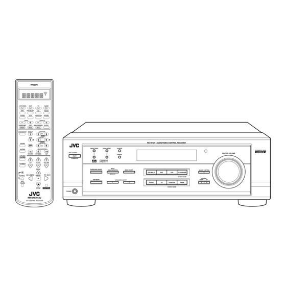
AUDIO/VIDEO CONTROL RECEIVER
RX-7012VSL
CATV/DBS
VCR
TV
AUDIO
DVD
DVD MUILTI
CD
FM/AM
TV/DBS
VCR
TAPE/CDR
PHONO
BASS
TREBLE
SURROUND
DSP
ANALOG/DIGITAL SLEEP
ON/OFF
MODE
INPUT
BASS BOOST EFFECT
+ CENTER –
1
2
3
MENU
TEST
+ REAR•L –
4
5
6
ENTER
SOUND
– REAR•R +
7/P
8
9
MUTING
– SUB WOOFER +
0
10
+10
STANDBY
RETURN
FM MODE
100 +
CA TV/DBS
CONTROL
CONTROL
STANDBY/ON
CH
TV VOL
VOLUME
TV/VIDEO
PLAY
/REW
PAUSE
FF/
TUNING
REC
PAUSE
STOP
CONTROL
PHONES
RM-SRX7012U
A/V CONTROL RECEIVER
RX-7012V AUDIO/VIDEO CONTROL RECEIVER
FM/AM TUNING
FM/AM PRESET
FM MODE
MEMORY
D I G I T A L
D I G I T A L
S U R R O U N D
INPUT
SURROUND ON/OFF
ANALOG/DIGITAL
BASS BOOST
DVD MULTI
DVD
INPUT ATT
DSP MODE
SPEAKERS ON/OFF
1
2
PHONO
CD
INSTRUCTIONS
MASTER VOLUME
ADJUST
SETTING
VCR
TV SOUND/DBS
SOURCE NAME
CONTROL
DOWN
UP
TAPE/CDR
FM/AM
SOURCE NAME
COMPULINK
Remote
D I G I T A L
For Customer Use:
Enter below the Model No. and Serial
No. which are located either on the rear,
bottom or side of the cabinet. Retain this
information for future reference.
Model No.
Serial No.
LVT0579-007A
[A]
Advertisement
Table of Contents

Related Manuals for JVC RX-7012VSL


Summary of Contents for JVC RX-7012VSL
- Page 1 AUDIO/VIDEO CONTROL RECEIVER RX-7012VSL CATV/DBS AUDIO DVD MUILTI FM/AM TV/DBS TAPE/CDR PHONO BASS TREBLE SURROUND ANALOG/DIGITAL SLEEP ON/OFF MODE INPUT BASS BOOST EFFECT + CENTER – MENU TEST + REAR•L – ENTER SOUND – REAR•R + FM/AM TUNING FM/AM PRESET MUTING –...
- Page 2 Warnings, Cautions and Others Caution –– Disconnect the mains plug to shut the power off completely. The switch in any position does not disconnect the mains line. The power can be remote controlled. CAUTION To reduce the risk of electrical shocks, fire, etc.: CAUTION •...
- Page 3 No obstructions in 15 cm from the back Bottom: No obstructions, place on the level surface. In addition, maintain the best possible air circulation as illustrated. Spacing 15 cm or more Wall or obstructions Front RX-7012VSL Stand height 15 cm or more Floor...
-
Page 4: Table Of Contents
Activating the DVD MULTI Playback Mode ... 27 COMPU LINK Remote Control System ... 28 AV COMPU LINK Remote Control System ... 29 Operating JVC’s Audio/Video Components ... 31 Operating Audio Components ... 31 Operating Video Components ... 33 Operating Other Manufacturers’ Video Equipment ... -
Page 5: Parts Identification
Parts Identification Become familiar with the buttons and controls on the receiver before use. Refer to the pages in parentheses for details. FM/AM TUNING FM/AM PRESET FM MODE STANDBY MEMORY STANDBY/ON D I G I T A L D I G I T A L S U R R O U N D INPUT SURROUND ON/OFF... -
Page 6: Getting Started
Getting Started This section explains how to connect audio/video components and speakers to the receiver, and how to connect the power supply. Before Installation General • Be sure your hands are dry. • Turn the power off to all components. •... -
Page 7: Connecting The Speakers
AM Antenna Connections Snap the tabs on the loop into the slots of the base to assemble the ANTENNA AM loop. FM 75 COAXIAL LOOP AM Loop Antenna Outdoor single vinyl-covered wire (not supplied) Turn the loop until you have the best reception. Notes: •... -
Page 8: Connecting Audio/Video Components
About the speaker impedance The required speaker impedance of the front speakers does differ depending on whether both the FRONT SPEAKERS 1 and FRONT SPEAKERS 2 terminals are used or only one of them is used. CASE 1 When you connect only one pair of front speakers Front speaker Use front speakers with 8... - Page 9 CD player CD player To audio output Cassette deck or CD recorder Cassette deck To audio input PHONO (REC) TAPE (PLAY) (REC) (PLAY) SOUND RIGHT LEFT AUDIO To audio input CD recorder Note: You can connect either a cassette deck or a CD recorder to the TAPE/ CDR jacks.
- Page 10 TV and/or DBS tuner To S-video input To composite video input PHONO Connect the TV to the MONITOR OUT jack to view the playback picture from the other connected video components. (REC) TAPE (PLAY) (REC) (PLAY) SOUND To audio RIGHT LEFT output AUDIO...
- Page 11 Digital connections This receiver is equipped with four DIGITAL IN terminals — one digital coaxial terminal and three digital optical terminals, and one DIGITAL OUT terminal. You can connect any digital equipment such as — • DBS tuner, • Digital TV broadcast tuner, •...
-
Page 12: Connecting The Power Cord
Connecting the Power Cord Before plugging the receiver into an AC outlet, make sure that all connections have been made. Plug the power cord into an AC outlet. Keep the power cord away from the connecting cables and the antenna. The power cord may cause noise or screen interference. We recommend that you use a coaxial cable to connect the antenna, since it is well-shielded against interference. -
Page 13: Basic Operations
Basic Operations The following operations are commonly used when you play any sound source. Turning the Power On and Off (Standby) On the front panel: To turn on the power, press STANDBY/ON . The STANDBY lamp goes off. The name of the current source (or station frequency) appears on the display. -
Page 14: Adjusting The Volume
Selecting different sources for picture and sound You can watch picture from a video component while listening to sound from another component. Press one of the audio source selecting buttons — PHONO, CD, TAPE/CDR, FM/AM, TV SOUND/DBS* (or TV/DBS on the remote control), while viewing the picture from a video component such as the VCR, DVD player, or DBS tuner, etc. -
Page 15: Muting The Sound
Muting the Sound From the remote control ONLY: Press MUTING to mute the sound through all speakers and headphones connected. “MUTING” appears on the display and the volume turns off (the volume level indicator goes off). To restore the sound, press MUTING again so that “OFF” appears on the display. -
Page 16: Basic Settings
Basic Settings Some of the following settings are required after connecting and positioning your speakers in your listening room, while others will make operations easier. Recording a Source For analog-to-analog recording You can record any analog source through the receiver to — •... -
Page 17: Setting The Subwoofer Information
Setting the Subwoofer Information Register whether you have connected a subwoofer or not. Before you start, remember... • There is a time limit in doing the following steps. If the setting is canceled before you finish, start from step 1 again. On the front panel ONLY: 1. - Page 18 2. Press CONTROL UP 5/DOWN ∞ to select the delay time of the rear speaker output. • Press CONTROL UP 5 to increase the delay time from 0 msec (“R_DELAY 0MS”) to 15 msec (“R_DELAY 15MS”). • Press CONTROL DOWN ∞ to decrease the delay time from 15 msec (“R_DELAY 15MS”) to 0 msec (“R_DELAY 0MS”).
-
Page 19: Digital Input (Digital In) Terminal Setting
Digital Input (DIGITAL IN) Terminal Setting When you use the digital input terminals, you have to register what components are connected to which terminals (DIGITAL IN 1/2/3/4). Before you start, remember... • There is a time limit in doing the following steps. If the setting is canceled before you finish, start from step 1 again. -
Page 20: Storing The Basic Settings And Adjustments
When playing a software encoded with the DTS Digital Surround, “AUTO” may not work properly and the following symptoms may occur: • Sound does not come out at the beginning of playback. • Noise comes out while using the searching or skipping function. -
Page 21: Receiving Radio Broadcasts
Receiving Radio Broadcasts You can browse through all the stations or use the preset function to go immediately to a particular station. Tuning in Stations Manually On the front panel: 1. Press FM/AM to select the band (FM or AM). The last received station of the selected band is tuned in. -
Page 22: Selecting The Fm Reception Mode
To tune in a preset station On the front panel: 1. Press FM/AM to select the band (FM or AM). The last received station of the selected band is tuned in. 2. Press FM/AM PRESET 5/ ∞ until you find the channel you want. •... -
Page 23: Using The Dsp Modes
** Manufactured under license from Digital Theater Systems, Inc. US Pat. No. 5,451,942 and other world-wide patents issued and pending. “DTS” and “DTS Digital Surround” are trademarks of Digital Theater Systems, Inc. ©1996 Digital Theater Systems, Inc. All rights reserved. ), you can use JVC... -
Page 24: Reproducing The Sound Field
These direct sounds and indirect sounds are the most important elements of the acoustic surround effects. JVC Theater Surround and DAP modes can create these important elements, and give you a real “being there” feeling. Early reflections... -
Page 25: Available Dsp Modes According To The Speaker Arrangement
Available DSP Modes According to the Speaker Arrangement Available DSP modes will vary depending on how many speakers are used with this receiver. Make sure that you have set the speaker information correctly (see page 14). Speaker arrangements Front speaker speaker Center speaker Rear... -
Page 26: Adjusting The Surround Modes
Adjusting the Surround Modes Once you have adjusted the Surround modes, the adjustment is memorized for each Surround mode. Dolby and DTS Surround adjustments Before you start, remember... • Make sure that you have set the speaker information correctly (see page 14). •... - Page 27 • Each time you press the button, the effect level changes as follows: DSP EFFECT 1 DSP EFFECT 5 As the number increases, JVC Theater Surround becomes stronger (normally set it to “DSP EFFECT 3”). MODE On the front panel: You can also use the buttons on the front panel to adjust the Surround modes.
-
Page 28: Adjusting The Dap Modes
Adjusting the DAP Modes Once you have adjusted the DAP modes, the adjustment is memorized for each DAP mode. Before you start, remember... • Make sure that you have set the speaker information correctly (see page 14). • There is a time limit in doing the following steps. If the setting is canceled before you finish, start from step 1 again. -
Page 29: Activating The Dsp Modes
SURROUND ON/OFF 2. Select and play a sound source. • To enjoy JVC Theater Surround, play back a software encoded with Dolby Surround and labeled with To cancel the DSP mode Press DSP MODE repeatedly until “DSP OFF” appears on the mark. -
Page 30: Using The Dvd Multi Playback Mode
Using the DVD MULTI Playback Mode This receiver provides the DVD MULTI playback mode for reproducing the analog discrete output mode of the DVD player. Before playing back a DVD, refer also to the manual supplied with the DVD player. Activating the DVD MULTI Playback Mode You can adjust the DVD MULTI playback mode while playing back a DVD using the analog discrete output mode on the DVD player. -
Page 31: Compu Link Remote Control System
COMPU LINK Remote Control System The COMPU LINK remote control system allows you to operate JVC audio components through the remote sensor on the receiver. To use this remote control system, you need to connect JVC audio components through the COMPU LINK (SYNCHRO) jacks (see below) in addition to the connections using cables with RCA pin plugs (see pages 5 and 6). -
Page 32: Av Compu Link Remote Control System
AV COMPU LINK Remote Control System The AV COMPU LINK remote control system allows you to operate JVC video components (TV, VCR, and DVD player) through the receiver. To use this remote control system, you need to connect the video components you want to operate, following the diagrams below and the procedure on the next page. - Page 33 1. If you have already plugged your VCR, DVD player, TV, and this receiver into the AC outlets, unplug their AC power cords first. 2. Connect your VCR, DVD player, TV, and this receiver as follows, using the cables with the monaural mini-plugs (not supplied).
-
Page 34: Operating Jvc's Audio/Video Components
Operating JVC’s Audio/Video Components You can operate JVC’s audio and video components with this receiver’s remote control, since control signals for JVC components are preset in the remote control. Operating Audio Components IMPORTANT: To operate JVC’s audio components using this remote control: •... - Page 35 CD changer After pressing CONTROL repeatedly until “CDDSC” appears on the display window, you can perform the following operations on the CD changer: PLAY3: Starts playing. Returns to the beginning of the current (or previous) track. ¢ ¢ ¢ ¢ ¢...
-
Page 36: Operating Video Components
COMPU LINK terminals (see page 29) in addition to the connections using cables with RCA pin plugs (see pages 6 and 7). • Some JVC VCRs can accept two types of the control signals — remote code “A” and “B.” Before using this remote control, make sure that the remote control code of the VCR connected to the VCR jacks is set to code “A.”... -
Page 37: Operating Other Manufacturers' Video Equipment
Operating Other Manufacturers’ Video Equipment This remote control supplied with the receiver can transmit control signals for other manufacturers’ VCRs, TVs, CATV converters, DBS tuners, and DVD players. By changing the transmittable signals from preset ones to the other manufacturers’, you can operate the other manufacturer’s components using this remote control. - Page 38 To change the transmittable signals for operating a CATV converter or DBS tuner 1. Press and hold CATV/DBS 2. Press CATV/DBS CONTROL. 3. Enter manufacturer’s code using buttons 1 – 9, and 0. See the list to the right to find the code. 4.
- Page 39 To change the transmittable signals for operating another manufacturer’s VCR 1. Press and hold VCR 2. Press VCR. 3. Enter manufacturer’s code using buttons 1 – 9, and 0. See the list to the right to find the code. 4. Release VCR The following button can be used for operating the VCR: Turns on and off the VCR.
- Page 40 To change the transmittable signals for operating another manufacturer’s DVD player 1. Press and hold AUDIO 2. Press DVD. 3. Enter manufacturer’s code using buttons 1 – 9, and 0. See the list to the right to find the code. 4.
-
Page 41: Troubleshooting
Troubleshooting Use this chart to help you solve daily operational problems. If there is any problem you cannot solve, contact your JVC service center. PROBLEM The display does not light up. No sound from speakers. Sound from one speaker only. -
Page 42: Specifications
Specifications Amplifier Output Power Audio Audio Input Sensitivity/Impedance (1 kHz): Audio Input (DIGITAL IN)* : *Corresponding to Linear PCM, Dolby Digital, and DTS Digital Surround (with sampling frequency — 32 kHz, 44.1 kHz, 48 kHz). Audio Output Level: Digital output: Signal-to-Noise Ratio (’66 IHF/DIN): Frequency Response (8 ) RIAA Phono Equalization:... - Page 43 FM tuner (IHF) Tuning Range: Usable Sensitivity: 50 dB Quieting Sensitivity: Signal-to-Noise Ratio (IHF-A weighted): Total Harmonic Distortion: Stereo Separation at REC OUT: Alternate Channel Selectivity: Frequency Response: AM tuner Tuning Range: Usable Sensitivity: Signal-to-Noise Ratio General Power Requirements: Power Consumption: Dimensions (W x H x D): Mass: 87.50 MHz to 108.00 MHz...
- Page 44 VICTOR COMPANY OF JAPAN, LIMITED 0501NHMMDWJEIN...