Table of Contents
Advertisement
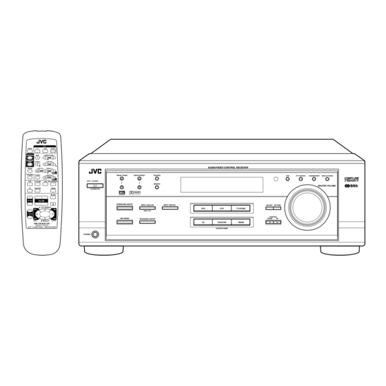
AUDIO/VIDEO CONTROL RECEIVER
RX-6010RBK / RX-6012RSL
SLEEP
TV
VCR
AUDIO
SURROUND
TEST
– SUBWOOFER +
1
2
3
5
SURROUND
MODE
EFFECT
– CENTER +
4
5
6
SOUND
– VCR CH +
– REAR•L +
8
9
7/P
5
MENU
TV/VIDEO
CD-DISC
– REAR•R +
FM/AM TUNING
10
+10
ENTER
DVD
TV SOUND
VCR ANALOG/DIGITAL
STANDBY
CD
TAPE/CDR
FM/AM
STANDBY/ON
D I G I T A L
MUTING
S U R R O U N D
+
+
TV VOL
VOLUME
–
8
–
SURROUND ON/OFF
£
PTY SEARCH
1
1
+
TV CH
–
7
PTY –
DISPLAY
+ PTY
RM-SRX6010R
REMOTE CONTROL
A/V CONTROL RECEIVER
PHONES
AUDIO/VIDEO CONTROL RECEIVER
FM/AM PRESET
FM MODE
MEMORY
D I G I T A L
INPUT ANALOG
INPUT DIGITAL
DVD
VCR
INPUT ATT
DSP MODE
SPEAKERS ON/OFF
CD
TAPE/CDR
SOURCE NAME
INSTRUCTIONS
EON
PTY SEARCH
TA/NEWS/INFO
DISPLAY MODE
MASTER VOLUME
ADJUST
SETTING
TV SOUND
CONTROL
DOWN
UP
FM/AM
D I G I T A L
For Customer Use:
Enter below the Model No. and Serial
No. which are located either on the rear,
bottom or side of the cabinet. Retain this
information for future reference.
Model No.
Serial No.
LVT0578-005A
[B]
Advertisement
Table of Contents

Related Manuals for JVC RX-6010RBK


Summary of Contents for JVC RX-6010RBK
- Page 1 AUDIO/VIDEO CONTROL RECEIVER RX-6010RBK / RX-6012RSL SLEEP AUDIO SURROUND TEST – SUBWOOFER + SURROUND MODE EFFECT – CENTER + SOUND – VCR CH + – REAR•L + MENU TV/VIDEO CD-DISC – REAR•R + FM/AM TUNING FM/AM PRESET FM MODE ENTER...
- Page 2 Warnings, Cautions and Others IMPORTANT for the U.K. DO NOT cut off the mains plug from this equipment. If the plug fitted is not suitable for the power points in your home or the cable is too short to reach a power point, then obtain an appropriate safety approved extension lead or consult your dealer.
-
Page 3: Safety Instructions
No obstructions in 15 cm from the back Bottom: No obstructions, place on the level surface. In addition, maintain the best possible air circulation as illustrated. Wall or obstructions SAFETY INSTRUCTIONS Spacing 15 cm or more RX-6010RBK/ RX-6012RSL Floor Front Stand height 15 cm or more... -
Page 4: Table Of Contents
Adjusting the Surround Modes ... 24 Adjusting the DAP Modes ... 26 Activating the DSP Modes ... 27 COMPU LINK Remote Control System ... 28 Operating JVC’s Audio/Video Components ... 29 Operating Audio Components ... 29 Operating Video Components ... 30 Troubleshooting ... 31 Specifications ... -
Page 5: Parts Identification
Parts Identification Become familiar with the buttons and controls on the receiver before use. Refer to the pages in parentheses for details. FM/AM TUNING FM/AM PRESET FM MODE STANDBY MEMORY STANDBY/ON D I G I T A L D I G I T A L S U R R O U N D SURROUND ON/OFF INPUT ANALOG... -
Page 6: Getting Started
Getting Started This section explains how to connect audio/video components and speakers to the receiver, and how to connect the power supply. Before Installation General • Be sure your hands are dry. • Turn the power off to all components. •... -
Page 7: Connecting The Speakers
AM (MW/LW) Antenna Connections Snap the tabs on the loop into the ANTENNA slots of the base to assemble the FM 75 AM (MW/LW) loop. COAXIAL LOOP AM (MW/LW) Loop Antenna Outdoor single vinyl-covered wire (not supplied) Turn the loop until you have the best reception. Notes: •... -
Page 8: Connecting Audio/Video Components
Connecting the subwoofer speaker You can enhance the bass by connecting a subwoofer. Connect the input jack of a powered subwoofer to the SUBWOOFER OUT jack on the rear panel, using a cable with RCA pin plugs (not supplied). Powered subwoofer Connecting Audio/Video Components You can connect the following audio/video components to this receiver. - Page 9 Video component connections Use the cables with RCA pin plugs (not supplied). Connect the white plug to the audio left jack, the red plug to the audio right jack, and the yellow plug to the video jack. MONITOR (REC) TAPE (PLAY) (REC) To audio...
-
Page 10: Connecting The Power Cord
Digital connections This receiver is equipped with two DIGITAL IN terminals — one digital coaxial terminal and one digital optical terminal. You can connect any component to one of the digital terminals using a digital coaxial cable (not supplied) or digital optical cable (not supplied). -
Page 11: Basic Operations
Basic Operations The following operations are commonly used when you play any sound source. Turning the Power On and Off (Standby) On the front panel: To turn on the power, press STANDBY/ON The STANDBY lamp goes off. The name of the current source (or station frequency) appears on the display. -
Page 12: Adjusting The Volume
Selecting different sources for picture and sound You can watch picture from a video component while listening to sound from another component. Press one of the audio source selecting buttons (CD, TAPE/CDR, FM/AM), while viewing the picture from a video component such as the VCR or DVD player, etc. -
Page 13: Adjusting The Subwoofer Output Level
Adjusting the Subwoofer Output Level You can adjust the subwoofer output level if you have selected “YES” for the “SUBWOOFER” (see page 11). Once it has been adjusted, the receiver memorizes the adjustment. Before you start, remember... • There is a time limit in doing the following steps. If the setting is canceled before you finish, start from step 1 again. -
Page 14: Basic Settings
Basic Settings Some of the following settings are required after connecting and positioning your speakers in your listening room, while others will make operations easier. Recording a Source You can record any source playing through the receiver to a cassette deck (or a CD recorder) connected to the TAPE/CDR jacks and the VCR connected to the VCR jacks at the same time. -
Page 15: Setting The Speakers For The Dsp Modes
Setting the Speakers for the DSP Modes To obtain the best possible surround sound of the DSP modes, you have to register the information about the speakers arrangement after all connections are completed. Before you start, remember... • There is a time limit in doing the following steps. If the setting is canceled before you finish, start from step 1 again. - Page 16 Crossover Frequency Setting Small speakers cannot reproduce the bass sound very well. So, if you have used a small speaker for any of the front, center, and rear channels, this receiver automatically reallocates the bass elements, originally assigned to the channel for which you have connected the small speaker, to another channel (for which you have connected the large speaker).
-
Page 17: Digital Input (Digital In) Terminal Setting
Digital Input (DIGITAL IN) Terminal Setting When you use the digital input terminals, you have to register what components are connected to which terminals (DIGITAL IN 1/2). Before you start, remember... • There is a time limit in doing the following steps. If the setting is canceled before you finish, start from step 1 again. -
Page 18: Storing The Basic Settings And Adjustments
When playing a software encoded with the DTS Digital Surround, “AUTO” may not work properly and the following symptoms may occur: • Sound does not come out at the beginning of playback. • Noise comes out while using the searching or skipping function. -
Page 19: Receiving Radio Broadcasts
Receiving Radio Broadcasts You can browse through all the stations or use the preset function to go immediately to a particular station. Tuning in Stations Manually On the front panel ONLY: 1. Press FM/AM to select the band (FM or AM — MW/LW). •... -
Page 20: Selecting The Fm Reception Mode
To tune in a preset station On the front panel: 1. Press FM/AM to select the band (FM or AM — MW/LW). The last received station of the selected band is tuned in. ANALOG TUNED 2. Press FM/AM PRESET 5/ ∞ until you find the channel you want. -
Page 21: Using The Rds (Radio Data System) To Receive Fm Stations
Using the RDS (Radio Data System) to Receive FM Stations RDS allows FM stations to send an additional signal along with their regular program signals. For example, the stations send their station names, as well as information about what type of program they broadcast, such as sports or music, etc. -
Page 22: Switching To A Broadcast Program Of Your Choice Temporarily
From the remote control: 1. Press PTY SEARCH while listening to an FM station. “PTY SELECT” flashes on the display. 2. Press and hold PTY + or PTY – until the PTY code you want appears on the display, while “PTY SELECT”... - Page 23 If there is no station broadcasting the program CASE 1 you have selected The receiver continues playing the current source (all sources except AM — MW/LW). ‘ When a station starts broadcasting the program you have selected, the receiver automatically switches to the station. The indicator of received PTY code starts flashing.
-
Page 24: Using The Dsp Modes
** Manufactured under license from Digital Theater Systems, Inc. US Pat. No. 5,451,942 and other world-wide patents issues and pending. “DTS” and “DTS Digital Surround” are trademarks of Digital Theater Systems, Inc. ©1996 Digital Theater Systems, Inc. All rights reserved. ), you can use JVC... -
Page 25: Reproducing The Sound Field
These direct sounds and indirect sounds are the most important elements of the acoustic surround effects. JVC Theater Surround and DAP modes can create these important elements, and give you a real “being there” feeling. Early reflections Direct sounds You can also use SURROUND on the remote control to activate the surround mode. -
Page 26: Available Dsp Modes According To The Speaker Arrangement
Available DSP Modes According to the Speaker Arrangement Available DSP modes will vary depending on how many speakers are used with this receiver. Make sure that you have set the speaker information correctly (see page 12). Speaker arrangements Front Front speaker speaker Center speaker... -
Page 27: Adjusting The Surround Modes
Adjusting the Surround Modes Once you have adjusted the Surround modes, the adjustment is memorized for each Surround mode. Dolby and DTS Surround adjustments Before you start, remember... • Make sure that you have set the speaker information correctly (see page 12). •... - Page 28 DSP EFFECT 1 DSP EFFECT 5 As the number increases, JVC Theater Surround becomes stronger (normally set it to “DSP EFFECT 3”). On the front panel: You can also use the buttons on the front panel to adjust the SURROUND Surround modes.
-
Page 29: Adjusting The Dap Modes
Adjusting the DAP Modes Once you have adjusted the DAP modes, the adjustment is memorized for each DAP mode. Before you start, remember... • Make sure that you have set the speaker information correctly (see page 12). • There is a time limit in doing the following steps. If the setting is canceled before you finish, start from step 1 again. -
Page 30: Activating The Dsp Modes
(See page 23 for more details.) SURROUND ON/OFF 2. Select and play a sound source. • To enjoy JVC Theater Surround, play back a software encoded with Dolby Surround and labeled with To cancel the DSP mode Press DSP MODE repeatedly until “DSP OFF”... -
Page 31: Compu Link Remote Control System
COMPU LINK Remote Control System The COMPU LINK remote control system allows you to operate JVC audio components through the remote sensor on the receiver. To use this remote control system, you need to connect JVC audio components through the COMPU LINK (SYNCHRO) jacks (see below) in addition to the connections using cables with RCA pin plugs (see page 5). -
Page 32: Operating Jvc's Audio/Video Components
Operating JVC’s Audio/Video Components You can operate JVC’s audio and video components with this receiver’s remote control, since control signals for JVC components are preset in the remote control. Operating Audio Components IMPORTANT: To operate JVC’s audio components using this remote control: •... -
Page 33: Operating Video Components
IMPORTANT: To operate JVC’s video components using this remote control: • Some JVC VCRs can accept two types of the control signals — remote code “A” and “B.” Before using this remote control, make sure that the remote control code of the VCR connected to the VCR jacks is set to code “A.”... -
Page 34: Troubleshooting
Troubleshooting Use this chart to help you solve daily operational problems. If there is any problem you cannot solve, contact your JVC service center. PROBLEM The display does not light up. No sound from speakers. Sound from one speaker only. -
Page 35: Specifications
Specifications Amplifier Output Power At Stereo operation: Front channels: 100 W per channel, min. RMS, driven into 8 at 1 kHz with no more than 0.9% total harmonic distortion. (IEC268-3/DIN) At Surround operation: Front channels: 100 W per channel, min. RMS, driven into 8 at 1 kHz with no more than 0.8% total harmonic distortion. - Page 36 VICTOR COMPANY OF JAPAN, LIMITED 0301NHMMDWJEIN...