Samsung MWR-WE10 Service Manual
Wired remote control
Hide thumbs
Also See for MWR-WE10:
- Installation manual (25 pages) ,
- User manual (14 pages) ,
- Scheduling instructions (10 pages)
Table of Contents
Advertisement
WIRED REMOTE CONTROL
MWR-WE10
Refer to the service manual in the GSPN(see the rear cover) for the more information.
Wired Remote Control
Basic : MWR-WE00
Model : MWR-WE10
Model Code : MWR-WE10
CONTENTS
1. Precautions
2. Product Specifications
3. Disassembly and Reassembly
4. Troubleshooting
5. Exploded Views and Parts List
6. PCB Diagram
7. Wiring Diagram
8. Schematic Diagram
Advertisement
Table of Contents
Troubleshooting

Related Manuals for Samsung MWR-WE10


Summary of Contents for Samsung MWR-WE10
- Page 1 Wired Remote Control Basic : MWR-WE00 Model : MWR-WE10 Model Code : MWR-WE10 WIRED REMOTE CONTROL CONTENTS 1. Precautions 2. Product Specifications 3. Disassembly and Reassembly 4. Troubleshooting 5. Exploded Views and Parts List 6. PCB Diagram MWR-WE10 7. Wiring Diagram 8.
-
Page 2: Table Of Contents
4-3 How to Download Micom Software ....................4-3-1 Micom Software Upgrade Kit ....................4-3-2 Upgrade Kit Switch setting ..................4-3-3 Micom Software Upgrading Order 5. Exploded Views and Parts List ....................6. PCB Diagram ............................7. Wiring Diagram ........................... 8. Schematic Diagram ........................... Samsung Electronics... -
Page 3: Precautions
- Be sure to ground the product if there is any danger of electric leakage due to water or moisture. ● Be sure to turn off the auxiliary power switch or pull out the power plug during replacement or repair of electric parts. - There is a danger of electric shock. Samsung Electronics... -
Page 4: Product Specifications
2) Application S/W – Basic control – Schedule control – Error display – Individual control of indoor unit – ERV individual control – Integrated control of indoor unit and ERV – Energy Saving function 3) Product materials: Box, Label, Manual Samsung Electronics... -
Page 5: Basic Product Preparation Changes
Product Specifications 2-1-2 Basic Product Preparation Changes Item Basic Model (MWR-WE00) Model made (MWR-WE10) Changes New Equipment - New hinge (Hinge used in folder-type Ass'y Case mobile phones) - New TOP/BOTTOM/DOOR - Addition of door button part New MAIN PBA... -
Page 6: Product Structure
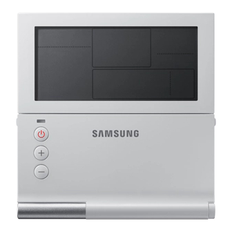
When a problem occurs during this process, it supported by places that can provide these services. Installation Method - Refer to the Installation guide. Other - You must refer to Installation guide and User guide. Samsung Electronics... - Page 7 (Green : Normal / Red : Need to be checked) Operation On/Off button Temperature Setting Button ● Without opening the cover of your Wired Remote Controller, you can turn the air-conditioner power On/Off or set the desired temperature. Samsung Electronics...
- Page 8 Displays Dust box cleaning alert/check/partial locking/full ⑱ locking Displays occupancy detection/Exhaust hood/External interconnection control/Auto clean/ Humidifying/Energy Commom function ⑲ saving/Outdoor air supply intake/ related information Centralized control ⑳ Displays S-Plasma Ion Displays Indoor CO density Displays Indoor humidity Samsung Electronics...
-
Page 9: Functional Development Specifications
Changes the air conditioner’s fan speed ⑤ Air Swing button Changes the air flow direction to move upward or downward ⑥ Temp. button Checks the indoor temperature ⑦ Quiet/Sleep button Selects Quiet or Sleep operation for the air conditioner Samsung Electronics... - Page 10 Select the desired operation for the Ventilator(ERV) Ventilator (ERV) Related Fan speed button Change the fan speed for your Ventilator(ERV) Buttons E.Saver button Begin Energy Saving Operation Clean up button Select air purification through the in/out load controls Samsung Electronics...
-
Page 11: Detailed Settings (User Settings)
● While setting the data, you can use the [>]/[<] buttons to set the range of SEG used. ● While configuring the setting, press the Esc button to exit to the sub-menu setting screen without saving the setting. Samsung Electronics... - Page 12 0-No use, 1-Use Use of LED (Red) (Y/N) 0-No use, 1-Use Ventilator(ERV) Delay Ventilator(ERV) 0-No use, 1-Use Application (Y/N) Delay Time Setting/Checking Delay Time 30~60 minutes 1 minute Reset to user mode defaults 0-No use, 1-Reset (except the current time) Samsung Electronics...
- Page 13 ● While setting the data, you can use the [<]/[>] buttons to set the range of Data bit. ● While configuring the setting, press the Esc button to exit to the setting sub-menu without saving your changes. 2-10 Samsung Electronics...
- Page 14 0 – No use, 1 - Use Indoor unit option checking (2) Filter time 0 – 2000 hours, 1 – 1000 hours Heating temperature compensation 0-2°C, 1-5°C EEV stop step in heating 0 – 1/80 steps, 1 – 80 Samsung Electronics 2-11...
- Page 15 Maximum no. of Connections: A maximum of 16 "indoor units + ERV" can be connected. Separate control between indoor unit and ventilation system (ERV) is possible. Integrated control between indoor unit and ventilation system (ERV) is possible. 2-12 Samsung Electronics...
-
Page 16: Installation Method
2. Arrange the power cable and the communication cable so that they fit in the housing along the edges of the rear cover. If you need more space for the wiring work, you can take it off. 15cm 10cm <When the cable is not concealed> <When the cable is concealed> Samsung Electronics 2-13... - Page 17 Maximum distance for connecting communication and power cable: 100m ● Screws on the PCB terminal must be tightened with less than 6N-cm tightening torque. If the tightening torque is greater, it may damage the screw thread. 2-14 Samsung Electronics...
-
Page 18: Tracking Your Indoor Unit From The Wired Remote Controller
● If you want to perform tracking again after installation, then press the Esc and Delete buttons at the same time for more than five seconds. ● Only the master Wired Remote Controller can display the total number of indoor units and ventilator(ERV). - Slave Wired Remote Controllers do not display the total number of units. Samsung Electronics 2-15... -
Page 19: Optional Materials Specifications
2-5 Optional Materials Specifications 2-5-1 Accessories Item Description Code No. Q’ty Remark Wired remote control DB93-11251B Cable tie DB65-10099B Cable clamp DB65-10074E Cable clamp 6002-000474 User Manual DB98-32810A Installation Manual DB98-32811A U-terminal DB60-00444A 2-16 Samsung Electronics... - Page 20 MEMO Samsung Electronics 2-17...
-
Page 21: Disassembly And Reassembly
Separate the door cover by pushing the bottom-right part of the product sideways. For assembling or dismantling, leave the door cover open about 130 degrees as in the image to do the work. Otherwise, the hinge may be incorrectly assembled, resulting in faulty operation. Samsung Electronics... - Page 22 Disassembly and Reassembly Image Procedure Unscrew the 6 screws assembled in the front cover to separate the PBA. Separate the PCB cover and the LCD connector to detach the PBA from the front cover. Separate the attached rubber keypad. Samsung Electronics...
-
Page 23: Troubleshooting
Example) 121 error occurred in No. 28 ventilation system (ERV). Ventilation system (ERV) E rror Found in Wired Remote Control Only the occurred error code is indicated. (No indication of the address where error occurred.) Example) 601 error occurred in wired remote control. Samsung Electronics... -
Page 24: Wired Remote Control Error List
- Damper error [error is detected when there is no input for 100 seconds (time for about 5 revolutions) during damper output] ● Please refer to the Installation guide of each equipment device for the error codes used for the indoor unit, the outdoor unit, and the ventilation system (ERV). Samsung Electronics... -
Page 25: Troubleshooting By Condition
12V(-12V) Is the IC03 (7805) output terminal 5V? Change 5V REGULATOR troubled ASS'Y PBA (DB93-11243A). Is the LCD connector properly connected? Change LCD WIRE Change of LCD modules Is it working normally after the change? Change PCB_ASS'Y (DB93-11243A) Samsung Electronics... -
Page 26: Communication Error Or Malfunction
ASS'Y PBA (DB93-11243A) Change ASS'Y PBA (DB93-11243A) C302 and GND at least 100KΩ? 100KΩ Check the communication of the indoor unit connected to wired remote control (this is not a problem with the wired remote control). Samsung Electronics... -
Page 27: How To Download Micom Software
4-3-2 Upgrade Kit Switch setting Upgrade Kit switch SW 3, 4, = OFF SW 1, 2 = Don't care SW 1, 2 = OFF Indise switch State SW 1 position SW 2 position If switch setting is wrong, then upgrading fails. Samsung Electronics... -
Page 28: Micom Software Upgrading Order
2. Can't be upgraded with empty software in the Soc. - Select a COM port and set the Baud rate at 115200bps. - Select “Indoor.” - Select the Micom software to download by pressing the "Select File" button. - Start downloading by pressing the "Download” button. Samsung Electronics... - Page 29 Troubleshooting Micom Software Upgrading Order (cont.) 3) The download is successful if the “Successful” message appears with the upgrade status. 4) If the "Download has failed" message appears, then check the connection status and start again. Samsung Electronics...
- Page 30 - Bootloader of SOC Micom is damaged. → Change PCB. - PBA is damaged. → Change PBA. - Problem found in the upgrade kit. → Change the upgrade kit. - Problem found in a cable (USB/Power/10-pin flat cable) → Change the relevant cable. Samsung Electronics...
-
Page 31: Exploded Views And Parts List
5. Exploded Views and Parts List 1-5-4 1-5-1 1-5-3 1-5-2 1-5-5 Samsung Electronics... -
Page 32: Exploded Views And Parts List
1-5-3 DB64-02600A BUTTON-KEY 1-5-4 DB63-02840A COVER-BUTTON 1-5-5 DB98-33083A ASS'Y-DOOR LABEL ART PAPER DB64-02599A WINDOW-DISPLAY DB02-00044A TAPE ETC-PROTECTOR DB61-04652A CASE-BOTTOM ASS'Y DB93-11266B ASS'Y DISPLAY-WE10 ASS'Y DB93-11243A ASS'Y PCB MAIN-SOLUTION ASS'Y DB64-02608B BUTTON-RUBBER KEY SILICON DB63-02867A COVER-PCB 6001-001413 SCREW-MACHINE M2,L5 Samsung Electronics... -
Page 33: Pcb Diagram
485 Communication part Battery 5V Power Doide 485 Communication with indoor unit Supply of power in the case of power In charge of non-polar function for suspension for Clock IC power ⑨ ⑩ Temperature sensor LCD Control IC Samsung Electronics... -
Page 34: Wiring Diagram
7. Wiring Diagram LCD connector (backlight power Development Service download and LCD data I2C download connector connector communication) (ASPRO) Communication connector (485 Power connector communication) (12V) Temperature sensor connector Samsung Electronics... -
Page 35: Schematic Diagram
8. Schematic Diagram Power Circuit Part(DC12V) Reset IC Part 485 Communication Temp. Sensor Part Download Part EEPROM Part Switch Part This Document can not be used without Samsung’s authorization. Samsung Electronics... - Page 36 Mideast & Africa http://mea.samsungportal.com © Samsung Electronics Co., Ltd. Dec. 2010. This Service Manual is a property of Samsung Electronics Co., Ltd. Printed in Korea. Any unauthorized use of Manual can be punished under applicable International and/or domestic law.