Carrier TP-WEM01 Installation Instructions Manual
Performance series cor thermostat, ac/hp wi-fi thermostat
Hide thumbs
Also See for TP-WEM01:
- Owner's manual (26 pages) ,
- Installation manual (26 pages) ,
- Advanced installation and configuration instrucrions (109 pages)

Related Manuals for Carrier TP-WEM01


Summary of Contents for Carrier TP-WEM01
-
Page 1: Installation Instructions
TP-- WEM01 Carrierr Côr™ Thermostat AC/HP Wi-Fir Thermostat Performance™ Series Installation Instructions A14493 NOTE: Read the entire instruction manual before starting the installation. -
Page 3: Table Of Contents
TABLE OF CONTENTS PAGE SAFETY CONSIDERATIONS ....... . . INTRODUCTION . -
Page 4: Safety Considerations
SAFETY CONSIDERATIONS Read and follow manufacturer instructions carefully. Follow all local electrical codes during installation. All wiring must conform to local and national electrical codes. Improper wiring or installation may damage thermostat. Recognize safety information. This is the safety- -- -alert symbol. When you see this symbol on the equipment and in the instruction manual, be alert to the potential for personal injury. -
Page 5: Introduction
INTRODUCTION The Carrier Côrt thermostat is a wall- -mounted, low- -voltage thermostat which maintains room temperature by controlling the operation of a heating and/or air conditioning system, both heat pump and air conditioner models. Your Côr thermostat has a color touch screen and interface similar to that used in smart phones. -
Page 6: Installation
INSTALLATION Installation Notes: The maximum wire size to be used in the installation is 22AWG (0.50mm2) with 0.8mm insulation No part of the control should be installed directly outdoors or in a cabinet outdoors The control assembly base should be mounted before wires are attached Thermostat location: Approximately 5 ft. - Page 7 Close to or in direct airflow from supply registers and return- - air registers. In areas with poor air circulation, such as behind a door or in an alcove. Compatible Systems Your Carrier Côr thermostat works with most centralized residential heating and cooling systems. Heating: up to 2 stages Cooling:...
- Page 8 Terminal Descriptions Cool transformer Heat transformer Heat pump reversing valve Y/Y1 Used for first stage of conventional A/C or first stage of heat pump compressor Used for second stage of conventional A/C or second stage of heat pump compressor W1, W2: Used for 1 - - 2 stages of conventional heat or 1 - - 2 stages of electric auxiliary heat (3 stages - - Intelligent heat staging configuration) 24VAC common...
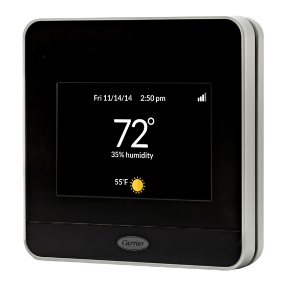
- Page 9 Items Included In Box A14494 Fig. 1 - - Carrier Côrr Thermostat A14495 Fig. 2 - - Small Backplate NOTE: The Mounting Plate (center) is removable for both backplates.
- Page 10 Items Included In Box (Cont.) A14496 Fig. 3 - - Large Backplate A14497 Fig. 4 - - Screws and Anchors...
- Page 11 Items Included In Box (Cont.) A14498 Fig. 5 - - Installation Instruction, Quick Start Guide, and Wire Labels Items You Will Need A. Phillips screwdriver B. Drill for drilling holes for the mounting anchors with a 3/16” drill bit. Before You Start Review the all the instructions before you start to ensure that there are no surprises during installation.
-
Page 12: Step 1. Power Off System
Step 1. Power Off the HVAC System WARNING ELECTRICAL OPERATION HAZARD Failure to follow this warning could result in injury or death. Before installing thermostat, turn off all power to equipment. There may be more than one power disconnect. Power off the HVAC system either by a switch at the indoor furnace or fan coil or at the circuit breaker box. -
Page 13: Step 2. Remove Existing Thermostat
Step 2. Remove Existing Thermostat Remove the cover from your old thermostat. Most snap off easily but some may be attached by screws. Note: If the old thermostat has 110/120V wires connected to the thermostat, it is a high voltage system and is not compatible with this thermostat. -
Page 14: Step 3. Attach Backplate To Wall
Discard any jumper wires between Rh, Rc, or R. This thermostat does not need them. They are jumpered internally. When done, remove the old thermostat base by unscrewing it from the wall. Be careful not to let any wires fall back into the wall. Discard or recycle old thermostat. - Page 15 Installing the optional large backplate If the small backplate doesn’t cover the marks left by the previous thermostat, attach the larger backplate instead. Remove the center piece from the small backplate by gently pushing the snap and pulling toward you. Insert the center piece into the large backplate, using the tabs on the right as a guide.
- Page 16 A14500 Fig. 7 - - Secure Backplate to Wall...
-
Page 17: Step 4. Connect The Wiring
Step 4. Connect the Wiring The wires from the wall should plug easily into the terminal blocks. Adjust length and routing of each wire to reach proper terminal and connector block on mounting base with 1/4- -in. (6 mm) of extra wire. Strip only 1/4 in. - Page 18 (AUX1) A14501 Fig. 8 - - Terminal Block Release Lever WARNING ELECTRICAL OPERATION HAZARD Failure to follow this warning could result in injury or death. Before installing thermostat, turn off all power to equipment. There may be more than one power disconnect. If you need help with the wiring, refer to the wiring diagrams at the back of this guide.
-
Page 19: Step 5. Power On System
System wiring diagrams covered are: Conventional heating and cooling systems Heat pumps (air or geothermal) Boilers or radiant heat systems Accessory devices: dehumidifiers, humidifiers, or ventilators Attach thermostat Push any excess wires back into the wall, and connect the thermostat to the backplate. -
Page 20: Features
3. If your device still doesn’t power on check the AC voltage between Rc and C or Rh and C and ensure it is 24V AC. FEATURES The Carrier Côr thermostat has a touch screen and interface similar to that used in smart phones. Accessing your web portal Register the Carrier Côr thermostat at www.Carrier.com/myhome to... -
Page 21: Wiring Diagrams
WIRING DIAGRAMS The following pages provide wiring diagrams for common HVAC equipment configurations. Y/Y1 (AUX2) W/W1 ACC+ (AUX1) ACC– Furnace Single Stage Cooling and Heating System A14502 Fig. 9 - - Air Conditioner- - Single Stage (Heat / Cool) - Page 22 WIRING DIAGRAMS (Cont.) Y/Y1 (AUX2) W/W1 ACC+ (AUX1) ACC– Furnace Y1 Y2 Y1 Y/Y2 W1 W2 R Furnace Two Stage Cooling and/or Heating System A14502B Fig. 10 - - Air Conditioner- - Two Stages each (Heat / Cool)
- Page 23 WIRING DIAGRAMS (Cont.) Y/Y1 (AUX2) W/W1 (AUX1) ACC+ ACC– O/B* Heat Pump Fan Coil or Furnace Single Stage Heat Pump and Auxiliary Heat * Connect to O/B terminal on furnace ir fan coil, if available A14503 Fig. 11 - - Heat Pump (Air or Geothermal) With Auxiliary Heat- - Single Stage...
- Page 24 WIRING DIAGRAMS (Cont.) Y/Y1 (AUX2) W/W1 (AUX1) ACC+ ACC– Y1 Y2 O/B* W2 Y1 Y/Y2 Fan Coil or Furnaces Heat Pump Stage 2 Heat Pump and Auxiliary Heat * Connect to O/B terminal on furnace ir fan coil, if available A14503B Fig.
- Page 25 WIRING DIAGRAMS (Cont.) Y/Y1 (AUX2) W/W1 (AUX1) ACC+ ACC– Air Handler Y1 Y2 W1** C O/B* Air Conditioner Boiler or Heat Pump Stage 2 Heat and Cool (If Applicable) *Reversing Valve for Heat Pumps Only **Do not connect W1 at HP (set enabled w/ defrost) A14504 Fig.
- Page 26 WIRING DIAGRAMS (Cont.) Accessory Devices The thermostat can control an accessory HVAC device like a humidifier, dehumidifier, or ventilation device from its dry contact ACC terminals (The ACC terminals do not provide 24V AC output). If the accessory is internally powered, connect the 24V to ACC+. Also connect the common for the accessory to common on the control board.
- Page 27 Approvals This product was designed and built in accordance to RoHS directive 2002/95/EC and contains no hazardous substances as defined by this directive. FCC Compliance Commission (FCC) Compliance Statement: This equipment has been tested and found to comply with the limits for a Class B digital device, pursuant to part 15 of the FCC Rules.
- Page 28 Connect the equipment into an outlet on a circuit different from that to which the receiver is connected. Consult the dealer or an experienced radio/TV technician for help. This device complies with part 15 of FCC rules. Opera- tion is subject to the following two conditions: 1.
- Page 29 2. this device must accept any interference, including interference that may cause undesired operation of the device. Le présent appareil est conforme aux CNR d’Industrie Canada applicable aux appareils radio exempts de licence. L’exploitation est autorisée aux deux conditions suivantes: 1.
- Page 30 Notes...
- Page 32 1- - 800- - CARRIER Copyright 2014 Carrier Corp. S 7310 W. Morris St. S Indianapolis, IN 46231 Edition Date: 10/14 Catalog No: TP---WEM---02SI Manufacturer reserves the right to change, at any time, specifications and designs without notice and without obligations.
Need help?
Do you have a question about the TP-WEM01 and is the answer not in the manual?
Questions and answers