Table of Contents
Advertisement
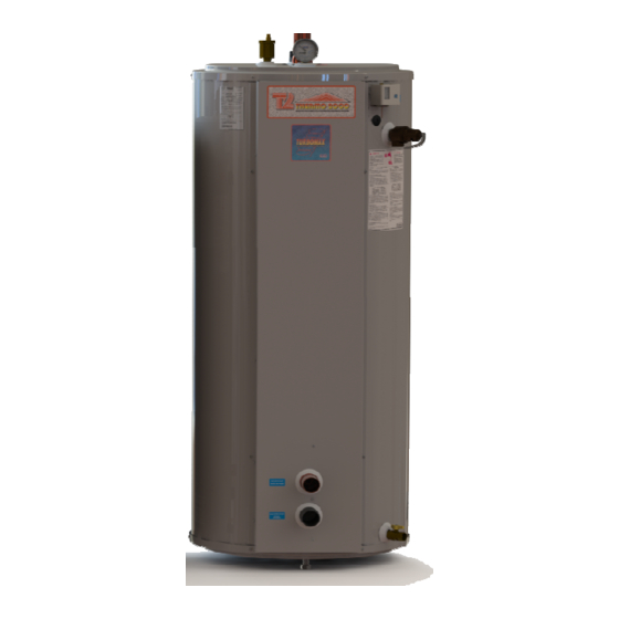
TURBOMAX
Instantaneous Indirect Water Heater
USE & CARE MANUAL
WITH INSTALLATION INSTRUCTIONS FOR THE CONTRACTOR
Your TURBOMAX
factory tested to provide years of trouble-free service. In order to insure the service intended,
the following information is provided to enable proper installation, operation, safety
precautions and maintenance of this product.
It is imperative that all persons who are expected to install, operate or adjust this water heater
read the instructions carefully so that they may understand how to do so.
Any questions regarding the operation, maintenance, service or warranty of this water heater
should be directed to the entity from whom it was purchased.
When all installation steps have been completed, replace this installation manual in its original
envelope, and keep in a safe place for future reference.
Note: Copyright 2005. Thermo 2000 Inc. All rights reserved. Turbomax® is a registered trademark of Thermo 2000 Inc.
Thermo 2000 reserves the right to modify at any time and without notice colors, components, materials, specifications or
model described in or shown in this document.
THERMO 2000 INC.
®
Instantaneous Indirect Water Heater has been carefully assembled and
®
Revision : July 2014
Advertisement
Table of Contents

Related Manuals for THERMO 2000 TURBOMAX 109


Summary of Contents for THERMO 2000 TURBOMAX 109
- Page 1 ® TURBOMAX Instantaneous Indirect Water Heater USE & CARE MANUAL WITH INSTALLATION INSTRUCTIONS FOR THE CONTRACTOR ® Your TURBOMAX Instantaneous Indirect Water Heater has been carefully assembled and factory tested to provide years of trouble-free service. In order to insure the service intended, the following information is provided to enable proper installation, operation, safety precautions and maintenance of this product.
-
Page 2: Specifications
® TURBOMAX Specifications The Turbomax indirect water has an internal copper domestic heat exchanger made of multiple helical copper tubes operating in parallel with a 150 psi.(200psi on ASME models All copper 109A) maximum operating pressure rating. components and assembly meet the low lead requirements for potable plumbing products and adhere to the NSF 61 standard (International Standard Drinking Water Systems Components Health Effects... -
Page 3: General Safety Precautions
General Safety Precautions Be sure to read and understand the entire Use & Care Manual before attempting to install or operate this water heater. Pay particular attention to the following General Safety Precautions. Failure to follow these warnings could cause property damage, bodily injury or death. - Page 4 Introduction WARNING priority to producing domestic hot water. Any demand for space heating is postponed until the The important safeguards and instructions water heater has reached a preset level. This appearing in this manual are not meant to delay in supplying the space heating zones is cover all possible conditions and situations usually not noticed by those occupying the living that may occur.
- Page 5 All models can be installed on combustible floors RESTAURANTS and in alcoves. Minimum clearance from If the water heater is to be installed in a combustible construction is 0 inches on all sides. restaurant or other location where the floor is A minimum 3 inch clearance on top, both sides frequently cleaned, it must be elevated to and in the rear and a minimum 24 inch...
- Page 6 Installation WARNING Use only clean copper or approved plastic pipe for water connections. Local codes or The manufacturer’s warranty does not cover regulations shall govern the exact type of any damage or defect caused by installation material to be used. or attachment or use of any special attachment other than those authorized by To minimize heat loss during non-draw periods,...
- Page 7 Basic Piping Schematic Zone Valve Zoning Requirements: 1. The installation must conform to local, state, provincial and national codes. In any case where instructions conflict with the above, let those codes take precedence. 2. This is a basic piping schematic. It as to be adapted to your application. 3.
- Page 8 Basic Piping Schematic Turbomax as a buffer tank on a radiant floor system Requirements: 1. The installation must conform to local, state, provincial and national codes. In any case where instructions conflict with the above, let those codes take precedence. 2.
- Page 9 TURBOMAX Use and Care Manual with Installation Instructions July 2014 Page...
- Page 10 TURBOMAX Use and Care Manual with Installation Instructions July 2014 Page...
- Page 11 DOMESTIC HOT WATER TEMPERATURE BOILER WATER CONNECTIONS & PRESSURE RELIEF VALVE This water heater may be connected individually, in multiples with others, or with an external An automatic temperature & pressure relief valve storage tank containing boiler water. If two with a temperature probe of sufficient length must ®...
- Page 12 PUMP & PIPE SIZING Proposed boiler water temperature drop through the water heater (TD) Boiler water temperature drop (TD) through Boiler water Domestic water the water heater supply final Simplified design methods based on a 20°F temperature temperature temperature drop (TD) of boiler water going through the water heater to heat up domestic 200 °F 180 °F...
- Page 13 Pipe sizing criteria commercial design purposes a safety factor of Proper selection of pipe size is important to 10 to 15 % be added to the values in the tables. efficient system operation. A large pipe size results in lower friction losses and may allow the What is a “foot of water”? A mass of water at selection of smaller, more economical pump.
- Page 14 Pressure loss from water flow in pipe fittings Piping system pressure drop calculation. and valves The pressure loss from friction in a closed piping In addition to the pressure loss in straight pipe, system is required to determine the required there will be pressure losses from turbulence pump head.
- Page 15 PIPING SYSTEM PRESSURIZATION device, it should not be considered an operating control. The objective of system pressure control is to limit the pressure on all system equipment to its Oxygen should be excluded from the system to allowable working pressure, to maintain maintain corrosion-free characteristics, both in minimum pressure for all normal operating pressurization and in the operating cycle.
- Page 16 WIRING Wiring must conform to National Electrical Code Circulator zoning wiring and to state or local code requirements having Components must be wired to ensure that only jurisdiction. the circulator for each zone is powered when demand for supply water occurs in that zone. The water heater, when installed, must be electrically grounded in accordance with local An optional multi-zone switching relay is...
- Page 17 TURBOMAX Use and Care Manual with Installation Instructions July 2014 Page...
- Page 18 TO ADDITIONAL R845 WIRING : CIRCULATOR ZONING RELAYS FOR OTHER ZONES WITH DOMESTIC PRIORITY R845A RELAY ZONE 2 POWER SUPPLY, PROVIDE DISCONNECT MEANS AND OVERLOAD PROTECTION AS REQUIRED. CONTROL CASE MUST BE CONNECTED TO EARTH GROUND. USE GROUNDING SCREWS PROVIDED. IF HIGH MASS BOILER, THE BOILER TEMPERATURE MUST BE MAINTAINED THERMOSTAT...
- Page 19 TO ADDITIONAL R845 WIRING : CIRCULATOR ZONING RELAYS FOR OTHER ZONES R845A RELAY ZONE 2 POWER SUPPLY, PROVIDE DISCONNECT MEANS AND OVERLOAD PROTECTION AS REQUIRED. CONTROL CASE MUST BE CONNECTED TO EARTH GROUND. USE GROUNDING SCREWS PROVIDED. IF HIGH MASS BOILER, THE BOILER TEMPERATURE MUST BE MAINTAINED THERMOSTAT CONSTANT BY USING THE BOILER'S...
- Page 20 TURBOMAX Use and Care Manual with Installation Instructions July 2014 Page...
- Page 21 Steam Installation boiler if all the air is eliminated from the WARNING ® TURBOMAX tank and also from the supply and return lines from the boiler. ® Do not connect TURBOMAX to high- pressure steam boilers. An explosion Ball valves must be installed on the supply line could occur and on the return line near the boiler to isolate ®...
- Page 22 Low Pressure Steam Boiler Basic Piping Schematic Using Condensate DOMESTIC COLD WATER SUPPLY BALANCING BALL VALVE DOMESTCI HOT VALVE TO PURGE AIR BOILER HEADERS: WATER MIXED OUT OF THE TANK SUPPLY & RETURN PIPES OF THE TURBOMAX STEEL PIPE #40 OR COPPER PIPE #TYPE L DOMESTIC HOT WATER...
- Page 23 TURBOMAX Use and Care Manual with Installation Instructions July 2014 Page...
- Page 24 Operation SAFETY PRECAUTIONS Leave all shutoff valves open. Return zone valve to automatic operation. Before operating this water heater, be sure to read and follow these instructions, as well as Check system for leaks and repair. the warnings printed in this manual. Failure to do so can result in unsafe operation of the Purge air from the remaining zones, if water heater resulting in property damage,...
- Page 25 When the temperature of the boiler water in the Set the desired cut-in setting first by turning the heater is below the setting on the tank control Temp. adjustment screw then set the desired (aquastat), the boiler and circulator should start. differential by turning the differential screw If a zone valve is used for this zone, it should open at this time.
- Page 26 Maintenance DANGER Properly maintained, your water heater will provide years of dependable, trouble-free service. It is recommended that a regular Before manually operating the relief valve, routine maintenance program be established make certain no one will be exposed to the and followed by the user.
- Page 27 TROUBLESHOOTING SYSTEM PROBLEMS SYMPTOM POSSIBLE CAUSE ACTION Insufficient System incapable of prioritizing boiler Install a pump or a valve-zoning panel with the domestic hot water water for domestic water use. domestic hot water priority feature. When (boiler supplies demand occurs for domestic hot water, the space heating and zoning panel turns off the space heating system hot water needs).
-
Page 28: Replacement Parts List
Replacement Parts List INSTRUCTIONS FOR PLACING A PART ORDER Address parts orders to the distributor or store where the heater water purchased. All parts orders should include: 1. Model number and Serial number of heater, from embossed plate. 2. Part Description & Part Number as noted below and number of parts desired Reference Part... - Page 29 Table 1: Friction Loss in Feet of Head Per 100 feet of Tube COPPER TUBE, TYPE "L" (nominal size in inches) Flow 1/2" 3/4" 1" 1-1/4" 1-1/2" 2" 2-1/2" 3" 4" Water U.S. 1.39 2.47 2.79 1.31 8.19 1.39 4.18 16.65 1.97 2.81...
- Page 30 Table 2: Friction Loss in Feet of Head Per 100 feet of Pipe SCHEDULE 40 STEEL PIPE (nominal size in inches) Flow 1/2" 3/4" 1" 1-1/4" 1-1/2" 2" 2-1/2" 3" 4" Water U.S. 1.06 1.39 2.11 4.77 1.20 1.21 3.17 9.98 1.81 2.50...
- Page 31 Table 3: Friction Losses Through Pipe Fittings & Valve Equivalent Feet of Straight Pipe for Fittings & Valves ( nominal size in inches) Fittings 1/2" 3/4" 1" 1-1/4" 1-1/2" 2" 2-1/2" 3" 4" 90° Elbow standard 1.6 ft 2.3 ft 2.7 ft 3.6 ft 4.5 ft...
- Page 32 Table 4: Friction Losses Through TURBOMAX Boiler Water Side (Primary Circuit) Pressure Drop VS Boiler Water Flow rate TURBOMAX Indirect Hot Water Heater OLD TURBOMAX TURBOMAX 23, 24 TURBOMAX TURBOMAX 23 & 24 33, 34, 44, 45 BOILER WATER FLOW RATE IN U.S. GALLONS PER MINUTE Domestic Water Side (Secondary Circuit) Pressure Drop VS Domestic Water Flow rate TURBOMAX Indirect Hot Water Heater...
- Page 33 Spreadsheet 1: Pump sizing. System Flow Rate & Friction Losses Through TURBOMAX piping circuit Step # 1 : Boiler Net Output System Flow rate Temperature Drop ÷ ÷ ÷ ÷ ÷ ÷ ÷ ÷ BTU per hour US GPM Flow rate thru TURBOMAX piping circuit °F Step # 2 : Flow rate...
- Page 34 Table 5: Water Content of TURBOMAX, Tubes, Pipes and Storage Tank TURBOMAX Boiler Water Content Model Tank Volume 119 US gallons TURBOMAX 72 US gallons TURBOMAX 48 US gallons TURBOMAX 48 US gallons TURBOMAX 36 US gallons TURBOMAX 36 US gallons TURBOMAX 26 US gallons TURBOMAX...
- Page 35 Table 6: Expansion Tank Sizing 40 °F 40 °F 40 °F Lower system temperature 180 °F 200 °F 220 °F Higher system temperature 12. psig 15. psig 18. psig Minimum operating pressure at tank 30. psig 30. psig 30. psig Maximum operating pressure at tank Volume Volume of Diaphragm...
- Page 36 Table 7: Expansion Tank Sizing 50 °F 50 °F 50 °F Lower system temperature 180 °F 200 °F 220 °F Higher system temperature 12. psig 15. psig 18. psig Minimum operating pressure at tank 30. psig 30. psig 30. psig Maximum operating pressure at tank Volume Volume of Diaphragm...
- Page 37 Spreadsheet 2: Volume of Boiler Water in System & Expansion Tank Selection Pipe or Tube Volume in Pipe or Tube Boiler Water content Diameter Gallons per 100 feet Length (summation) ÷ ÷ ÷ ÷ Inches US Gallons Feet US Gallons ÷...
- Page 38 Thermo 2000’s head office or authorized depot with defect unit together with the following information: Turbomax model and serial number, copy of the original sales receipt and owner’s identification certificate. THERMO 2OOO INC. 500, 9e Avenue, Richmond (Qc) Canada J0B 2H0 Phone: (819) 826-5613 Fax: (819) 826-6370 www.thermo2000.com...
Need help?
Do you have a question about the TURBOMAX 109 and is the answer not in the manual?
Questions and answers