Table of Contents
Advertisement
Advertisement
Table of Contents

Related Manuals for Miranda Kaleido-Solo


Summary of Contents for Miranda Kaleido-Solo
- Page 1 Kaleido-Solo 3G/HD/SD SDI to HDMI Converter Guide to Installation and Operation M865-9900-204 08 February 2011 Miranda Technologies Inc. 3499 Douglas-B.-Floreani St-Laurent, Québec, Canada H4S 2C6 Tel. 514-333-1772 Fax. 514-333-9828 www.miranda.com © 2011 Miranda Technologies Inc.
-
Page 2: Safety Compliance
Voltage dips, short-interruption and voltage variation immunity Radiated EMF Immunity – RF 900 MHz pulsed ENV 50204 How to contact us: For technical assistance, please contact the Miranda Technical support centre nearest you: Americas Asia Europe, Middle East, Africa, UK Telephone:... -
Page 3: Table Of Contents
GUIDE TO INSTALLATION AND OPERATION Table of Contents 1. Kaleido-Solo 3G/HD/SD Video to HDMI Converter ..............1 Introduction ............................1 Key features and benefits ........................2 Block Diagram ............................. 3 Output example ........................... 3 Installation ..........................4 Unpacking ............................4 Connector Panel .......................... - Page 4 GUIDE TO INSTALLATION AND OPERATION Annex 2: AFD Functions ....................... 59 10 Annex 3: Installing the Optical Interface ................63 11 Annex 4: SFP module and description ................. 65 12 Annex 5: Mounting bracket ....................66 iv | Kaleido-Solo...
-
Page 5: Kaleido-Solo 3G/Hd/Sd Video To Hdmi Converter
Kaleido-Solo provides automatic video input format detection, and supports a wide variety of video resolutions, including 525i, 625i, 720p, 1080i and 1080p. Kaleido-Solo is available in two versions: KS-900 and KS-910. These two versions are identical except that the KS- 900 does not offer loudness and dialnorm monitoring. -
Page 6: Key Features And Benefits
Aspect ratio markers Time Code AFD/WSS/VLI Dynamic UMD (Under Monitor Display) History graph of audio loudness levels and dialnorm Easy configuration using on-screen menus Failsafe mechanism for unsupported monitor resolutions Convenient mounting bracket included 2 | Kaleido-Solo... -
Page 7: Block Diagram
GUIDE TO INSTALLATION AND OPERATION 1.3 Block Diagram The following block diagram shows the functionality of the Kaleido-Solo. Figure 1 - Functional Block Diagram 1.4 Output example Figure 2 - Elements of the on-screen display Kaleido-Solo | 3... -
Page 8: Installation
GUIDE TO INSTALLATION AND OPERATION 2 Installation 2.1 Unpacking Make sure the following items have been shipped with your Kaleido-Solo. If any of the following items are missing, contact your distributor or Miranda Technologies Inc. Kaleido-Solo Power Supply ... -
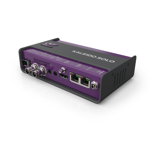
Page 9: Connector Panel
GUIDE TO INSTALLATION AND OPERATION 2.2 Connector Panel The rear connector panel incorporates all inputs and outputs associated with the Kaleido-Solo, with the exception of a Remote Control connector (currently unused and sold separately) on the front panel. Connections Label... -
Page 10: Powering Up
Your monitor should turn on and you should see content of the SDI input. If you only use the optional optical input you won‟t be able to see any video until 15 seconds approximately. In this step Kaleido-Solo will use all factory default parameters for video and audio. -
Page 11: Operating Controls And Functions
GUIDE TO INSTALLATION AND OPERATION 3 Operating Controls and Functions The Kaleido-Solo is configured and operated using the four buttons on the front panel to navigate through on-screen menus displayed on the video monitor. There are also some non-menu functions for these buttons. -
Page 12: Special Button Functions
Hold for 5 seconds to enter safe mode (640x480) Analog audio volume control (when not in menu) 3.2 Status LED The status LED in the lower left corner of the front panel displays the current status of the Kaleido-Solo. Status Description... -
Page 13: Behavior
1920x1080p 59.94 1080p 59.94Hz 1920x1080p 24 1080p 24Hz 1920x1080p 23.98 1080p 23.98Hz 1920x1080p 50 1080p 50Hz 1920x1080p 25 1080p 25Hz 1920x1080 PsF 24 1920x1080 PsF 24 1920x1080 PsF 23.98 1920x1080 PsF 23.98 1920x1080 PsF 25 1080i 50Hz Kaleido-Solo | 9... -
Page 14: Supported Output Resolution
: 1680x1050p60 1440x900p 60/59.94/50 e.g. : 1440x900p60 1366x768p 60/59.94/50 e.g.: 1366x768p60 640x480p 60/59.94 e.g.: 640x480p60 Note that 640x480p 60 is the safe mode resolution. 4.1.3 Supported frame rate processing Frame rate input 60Hz monitor 50Hz monitor 60/59.94/30/29.97/24/23.98 50/25 10 | Kaleido-Solo... -
Page 15: Scaling Limitations
4.1.5 Processing delay The Kaleido-Solo‟s video processing delay is about 1 frame when the input frame rate is equal to half of the output rate (e.g.: p60 to p60, i60 to p60). In all other cases the processing delay is kept at its minimum. -
Page 16: Configuration (Menu)
Move up and down the options in the current level by using the UP and DOWN buttons Move back to the previous level on the left by pushing the ESCAPE button Move on to the next level, which will appear on the right, by pushing the ENTER button. 12 | Kaleido-Solo... - Page 17 When you have finished using the menu, push ESCAPE until you are in the left-most column, and then once more. The menu will disappear from the screen. Kaleido-Solo remembers the last path you used, so you can retrace your steps back to the last parameter changed quickly, just by pushing ENTER until you arrive at the value list.
-
Page 18: Status Menu
Metadata section. Shows the format at the Kaleido-Solo‟s output. Output Monitor Shows the prefered monitor resolution detected by the Kaleido-Solo. Audio status 1 to 16 Shows the type of audio detected per channel (PCM, NPCM, AC3, DOLBY E or N/A). -
Page 19: Video Menu
GUIDE TO INSTALLATION AND OPERATION 5.2 Video Menu Input Selection Select the input signal to be used by the Kaleido-Solo. Choose between: Electrical: The signal arriving on the rear-panel BNC connector. Optical: The signal arriving via optical fiber into the SFP module installed in the rear panel. - Page 20 When the input signal is 1080i 50 Hz, it is not possible to automatically detect whether the video is 25 Hz PsF video or 50 Hz interlaced. If PsF is known to be present it must be manually selected, so that the Kaleido-Solo can properly process the video image (de-interlacing for interlaced video;...
- Page 21 (e.g.: 4:3_8) to process (scale) the video accordingly. Aspect Ratio - Forced HD Select the AFD code that will be forced on the Kaleido-Solo output for HD input video signals when scaler is set to auto. Refer to: Annex 2: AFD Functions...
-
Page 22: Metadata Menu
Aspect ratio status shows the presence of an AFD code following the selected aspect ratio parameters (Detected or N/A). TC Status: Time code status shows the presence of time code (Detected or N/A). DM Status: Dolby metadata shows the presence of the selected SDID (Detected or N/A). 18 | Kaleido-Solo... - Page 23 GUIDE TO INSTALLATION AND OPERATION Aspect ratio - AFD source Select the source of the metadata that will be used by this Kaleido-Solo for aspect ratio control: AFD: Selects AFD as the source for HD and SD (525, 625) aspect ratio descriptor.
- Page 24 An SDI signal could contain up to 9 different Dolby metadata packets. This specifies which one to select. Some of the information contained in the selected packet could affect the behavior of the loudness (see section 0) or downmix (see section 0). 20 | Kaleido-Solo...
-
Page 25: Audio Menu
GUIDE TO INSTALLATION AND OPERATION 5.4 Audio Menu 5.4.1 Audio - General Output Selection Select the audio channel pair that will be sent to the Kaleido-Solo outputs (HDMI, S/PDIF and analog) for monitoring. Ch. 1-2 Monitor channel 1 (left) and 2 (right). Ch. 15-16 Monitor channel 15 (left) and 16 (right). - Page 26 Enable audio insertion in HDMI. Disable audio insertion in HDMI (this could help with some monitors that does not support compressed audio). Volume (Analog) Adjust the volume of the Kaleido-Solo‟s analog audio output. 0 dB The input level is unchanged. -96 dB The input level is attenuated.
-
Page 27: Audio - Alm
BARGRAPH_NORDIC_PPM (IEC60268-10 type I) Analog peak BARGRAPH_DIN_PPM (IEC60268-10) Analog peak 5.4.2 Audio - ALM True Peak Mode Checked All ALMs are in true peak mode (as explained in document ITU-R BS.1770-1 annex Unchecked All ALMs are in standard mode. Kaleido-Solo | 23... - Page 28 Select the channels you want to assign to the second (rightmost) 5.1 ALM. To see this 5.1 ALM you must enable it - see section 5.5.3. Stereo Assignment Select input channels (by pair) for each of the eight available ALMs. 24 | Kaleido-Solo...
-
Page 29: Audio - Downmix
GUIDE TO INSTALLATION AND OPERATION 5.4.3 Audio - Downmix The Kaleido-Solo provides two channels of audio output. If the input audio is a 5.1 surround sound signal, it must be downmixed for monitoring. This menu provides the configuration for the downmix. - Page 30 -4.5 dB -6 dB Mute LFE is not used in the downmix. This gain is always applied to LFE even if the operation mode is set to follow metadata because there is no such information in the metadata. 26 | Kaleido-Solo...
- Page 31 Manual – Mode Stands for Left total/Right total. It‟s a downmix suitable for decoding with a Dolby Pro Logic surround LtRt sound device. Stands for Left only/Right only. It‟s a downmix suitable for stereophonic sound playback. LoRo Kaleido-Solo | 27...
- Page 32 Select a dialnorm value to use during the manual downmix. The gain will be applied after the downmix. -1 dBFS 30 dB gain is applied. -31 dBFS Unity gain is applied (no gain, no attenuation). The gain applied (dBFS) is calculated as follow: Gain applied (dBFS) = 31 dBFS + Dialnorm 28 | Kaleido-Solo...
- Page 33 Input Selection Assign input channels to the L, R, C, LFE, Ls and Rs downmix inputs. Note that if compressed audio is detected on one or more of the assigned channels, the downmix audio will be muted. Kaleido-Solo | 29...
-
Page 34: Audio - Loudness
GUIDE TO INSTALLATION AND OPERATION 5.4.4 Audio - Loudness Loudness measurement is available in Kaleido-Solo model 910 only. The Kaleido-Solo supports two independent loudness measurements, called “1 Loudness” and “2 Loudness”. You can configure both in this menu. Having two separate measurements is useful if, for example, you want to measure one 5.1 and one stereo pair simultaneously. - Page 35 A coding mode 2/0 (L, R) will only permit channels to be assigned to the L and R positions. A coding mode 1/0 (C) will only permit a channel to be assigned to the C position. Note that you cannot assign the same channel twice. Kaleido-Solo | 31...
-
Page 36: Audio - Loudness Advanced
Note that if there are stars in front of the menu name (e.g.: ** EBU Mode) it means that the measurement respects the EBU mode except the parameter or parameters that were manually changed that could affect the results. 32 | Kaleido-Solo... - Page 37 -23 dBFS window window window integrated measure A-85 400 ms sliding 10 sec sliding infinite sliding none -24 dBFS window window window Refer to EBU R128 or ATSC A/85 specification for more specific details. Kaleido-Solo | 33...
-
Page 38: Audio - Loudness Control
- no new LRA measurements will be displayed until the “Short-Term Time Window” has elapsed (e.g.: For EBU mode, this value is 3 sec). 1st Loudness/2nd Loudness - Reset Reset all loudness measurements - traces on the loudness (1 or 2) chart. Cancel Return to the menu without any alteration. 34 | Kaleido-Solo... - Page 39 Force both loudness charts 1 and 2 to pause. Running Force both loudness charts 1 and 2 to run. All - Reset Loudness engine is reset, past infinite integration is lost and measurement will start from scratch. Cancel Return to the menu without any alteration. Kaleido-Solo | 35...
-
Page 40: On Screen Display (Osd) Menu
GUIDE TO INSTALLATION AND OPERATION 5.5 On Screen Display (OSD) Menu 5.5.1 OSD - General Transparency Affects all OSD elements except the menu Transparent Opaque 36 | Kaleido-Solo... - Page 41 Enable the display of OSD elements. Each OSD element has its own show/hide parameter e.g.: loudness chart. Unchecked: Disable all OSD elements, irrespective of their individual Show/Hide setting. Note that if the OSD is turned off the video signal is still displayed. Kaleido-Solo | 37...
-
Page 42: Osd - Loudness
GUIDE TO INSTALLATION AND OPERATION 5.5.2 OSD - Loudness Loudness measurement is available in Kaleido-Solo model 910 only. This menu controls the appearance of the on-screen loudness chart. Loudness 1/Loudness 2 Checked Display the (1 or 2) loudness chart. Unchecked Hide the (1 or 2) loudness chart. - Page 43 Both loudness charts will use a scale of -59.0 LUFS/LKFS to -5.0 LUFS/LKFS) (-36.0 LU/dB to +18.0 LU/dB). Compact Display the compact form of both loudness charts. The compact form includes the momentary meter and measurement summary. In this case the momentary meter will use the +9 scale. Kaleido-Solo | 39...
- Page 44 Meter that represents the momentary measurement. Loudness chart (compact) The compact form is represented by the left section of the full loudness chart combined with the momentary meter. Note that the momentary scale in compact mode is fixed to +9. 40 | Kaleido-Solo...
-
Page 45: Osd - Alm
Show scales on all audio level meters - levels are in dB. Unchecked Hide scales on all audio level meters. Control - Channel ID Checked Show the identity (channel numbers) on all audio level meters. Unchecked Show the identity (channel numbers) on all audio level meters. Kaleido-Solo | 41... - Page 46 EBU Digital (Digital type VU (Green bars) + Peak (White horizontal lines)) (IEC60268-18) VU Meter (Analog VU) (IEC60268-17) UK PPM (Analog peak) (IEC60268-10 type IIa) EBU PPM (Analog peak) (IEC60268-10 type IIb) Nordic PPM (Analog peak) (IEC60268-10 type I) DIN PPM (Analog peak) (IEC60268-10) 42 | Kaleido-Solo...
- Page 47 GUIDE TO INSTALLATION AND OPERATION Note that the numbers 1 to 7 on black background (image bottom numbers) are just here for the purpose of the manual and cannot be displayed on the video output of the Kaleido-Solo. Scale Scale is the graduation in dB of an audio level meter.
- Page 48 GUIDE TO INSTALLATION AND OPERATION 5.1 channel assignment Stands for front left Stands for center Stands for front right Stands for left surround Stands for subwoofer Stands for right surround 44 | Kaleido-Solo...
-
Page 49: Osd - Others
Time Code - Show Set the location on the display monitor where the extracted time code will be displayed, or turn time code display off. Top Left Top Center Top Right Bottom Left Bottom Center Bottom Right Kaleido-Solo | 45... - Page 50 Top Left Top Center Top Right Bottom Left Bottom Center Bottom Right 4:3 Markers - Line Choose whether to show 4:3 markers within the 16:9 video displays No Lines Marker are not displayed. Lines Markers are displayed. 46 | Kaleido-Solo...
- Page 51 Under monitor display (UMD) Dynamic text can be driven by some automation systems. Note that the ID number for the Kaleido-Solo UMD text box is „0‟ and the port number is „13000‟. This is useful when configuring the third-party automation system.
-
Page 52: Ethernet
Internet Protocol for communication. You can set the address IP here. Netmask Netmask configures the subnetwork. A subnetwork, or subnet, is a logically visible subdivision of an IP network. You can set the netmask here. 48 | Kaleido-Solo... - Page 53 After IP, Netmask and Gateway addresses are entered, navigate to the “Apply Settings” button and click on it. Wait few seconds to see the Status box information change accordingly. If DHCP is checked, the IP is the one provided by your network DHCP server. Kaleido-Solo | 49...
-
Page 54: General
GUIDE TO INSTALLATION AND OPERATION 5.7 General Factory The Kaleido-Solo stores a set of factory-specified values for the various user-configurable settings Yes: Reset all configuration to their factory default. Those factory default may change over product version changes such as a software update. -
Page 55: About Menu
This screen identifies this specific Kaleido-Solo‟s model and version number. This information will be required if you need assistance from Miranda technical support. There are other elements on this page labeled B, C, F and M that could be needed by the Miranda technical support. Kaleido-Solo | 51... -
Page 56: Safe Mode
The Safe Mode Menu will be shown on the screen, allowing some operating parameters of the Kaleido-Solo to be set manually. Resolution The Output resolution of the Kaleido-Solo can be set to one of the following fixed values, or it can be set to follow the EDID from the monitor. EDID: Follow the prefered monitor resolution every time (power-up or connect a new monitor). - Page 57 Push ENTER to apply the settings made in this menu and close the menu. At the bottom of the menu, the resolutions of the selected input, the current output, and the monitor display as derived from the EDID are shown. Kaleido-Solo | 53...
-
Page 58: Upgrade Procedure
GUIDE TO INSTALLATION AND OPERATION 6 Upgrade Procedure When it becomes necessary to upgrade the Kaleido-Solo to a new software or firmware version, use the procedure described here. The Kaleido-Solo serves a web page that is the portal for upgrading the device. - Page 59 Click the Upgrade button to begin the upgrade procedure. A pop-up warning will appear, listing things you should NOT do while the Kaleido-Solo is upgrading: When you are ready to proceed, click OK. The main window will show that the upgrade is in progress, and remind you of the things NOT to do.
- Page 60 GUIDE TO INSTALLATION AND OPERATION When the upgrade is complete, the main window will notify you that it was successful, and advise you to reboot your Kaleido-Solo. Reboot the Kaleido-Solo to put the upgraded software into service. 56 | Kaleido-Solo...
-
Page 61: Specifications
Signal: IEC 60958 Level: 0.5 Vp-p ±20% Impedance: 75 ohm unbalanced Sampling rate: 48 kHz ETHERNET Connector: RJ-45 PROCESSING Signal path: 8 bits Processing delay: 1 frame ELECTRICAL Voltage range: 6 to 17 VDC Power: 10 W Kaleido-Solo | 57... -
Page 62: Annex 1: Glossary
GUIDE TO INSTALLATION AND OPERATION 8 Annex 1: Glossary Concept Description EBU R128 Refer to EBU technical document 3341 ATSC A/85 Refer to document number: ITU-R BS.1770 58 | Kaleido-Solo... -
Page 63: Annex 2: Afd Functions
GUIDE TO INSTALLATION AND OPERATION 9 Annex 2: AFD Functions The charts below show the conversions that will be performed by the Kaleido-Solo by selecting the Active Format Descriptor (AFD). In the images shown in the chart: BLACK Indicates that this portion of the transmitted image will be black... - Page 64 16:9 frame (4:3_15) (4:3_15) (16:9_15) 16:9 image shoot and protect 16:9 in a 16:9 image shoot and protect 16:9 in a 16:9 Full frame image in a 16:9 frame 4:3 frame (anamorphic) 4:3 frame (anamorphic) (16:9_8) (16:9_8) (16:9_8) 60 | Kaleido-Solo...
- Page 65 4:3 Full frame image in a 4:3 frame 4:3 Pillar-box image in 16:9 frame (4:3_8) (16:9_9) (16:9_9) 16:9 Protected Full frame image in a 16:9 Letterbox image in 4:3 frame 16:9 Protected Full frame image in a 16:9 frame 16:9 frame (4:3_10) (16:9_10) (16:9_10) Kaleido-Solo | 61...
- Page 66 16:9 frame 16:9 frame (4:3_11) (16:9_14) (16:9_14) 16:9 Image shoot and protect 4:3 in a 4:3 Full frame image in a 4:3 frame 16:9 Image shoot and protect 4:3 in a 16:9 frame 16:9 frame (4:3_8) (16:9_15) (16:9_15) 62 | Kaleido-Solo...
-
Page 67: Annex 3: Installing The Optical Interface
Installing an SFP module 1. Make sure that the bale clasp lever is in the closed position 2. Slide the module straight into the socket, and push gently until it clicks into position. Connecting the fiber optic cables Kaleido-Solo | 63... - Page 68 Do NOT pull on the bale clasp lever to remove the module, as it is easily damaged You may find that you need to wiggle the module, or perhaps push it into the slot a bit, before it will release and slide out. 3. Insert a dust plug into the SFP module. 64 | Kaleido-Solo...
-
Page 69: Annex 4: Sfp Module And Description
SFP-T-S13-LC Single fiber Tx (output) cartridge at 1310 nm with LC/PC connector. DUAL-TX SFP-TT-S13S13-LC Dual fiber Tx (output) cartridge at 1310 nm with LC/PC connector. RXTX SFP-RT-S13-LC Dual fiber Rx/Tx (input/output) cartridge 1310 nm with LC/PC connector. Kaleido-Solo | 65... -
Page 70: Annex 5: Mounting Bracket
GUIDE TO INSTALLATION AND OPERATION 12 Annex 5: Mounting bracket Do not use any screws other than the ones provided, or it may cause damage to the Kaleido-Solo. 66 | Kaleido-Solo...
Need help?
Do you have a question about the Kaleido-Solo and is the answer not in the manual?
Questions and answers