Table of Contents
Advertisement
Quick Links
© 2005 Victor Company of Japan, Limited
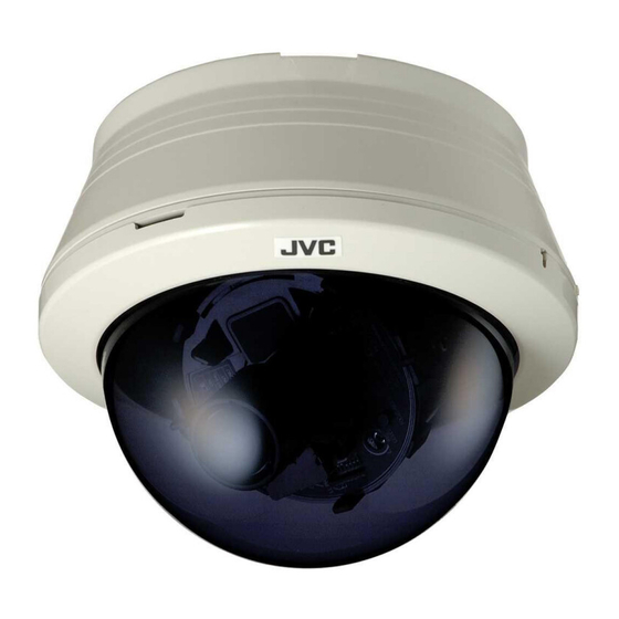
DOME CAMERA
TK-C210FW
TK-C215V4
TK-C215V12
For Customer Use:
Enter below the Serial No. which is located on the body.
Retain this information for future reference.
Model No.
Serial No.
Printed in Thailand
LST0308-001B-H
TK-C210FW/TK-C215V4/TK-C215V12
INSTRUCTIONS
LST0308-001B-H
Advertisement
Table of Contents

Summary of Contents for JVC TK-C210FW
-
Page 1: Dome Camera
© 2005 Victor Company of Japan, Limited DOME CAMERA TK-C210FW TK-C215V4 TK-C215V12 For Customer Use: Enter below the Serial No. which is located on the body. Retain this information for future reference. Model No. TK-C210FW/TK-C215V4/TK-C215V12 Serial No. Printed in Thailand... -
Page 2: Introduction
Please consult your nearby equipment generates, uses, and can radiate authorized JVC dealer for more details. radio frequency energy and, if not installed and used in accordance with the instructions, may The ceiling to mount the camera has to be... -
Page 3: Characteristics
(symbol provided by RETAC) 380,000 pixels and a high-resolution video processing circuit. * 500 TV lines and 48 dB in the case of TK-C210FW Enlarged Shooting Range The adjustment range of the shooting direction is wide and mounting of the camera... -
Page 4: Table Of Contents
Installation and connection About Connection Cables ... 14 Video signal cables ... 14 Installing the Ferrite core (TK-C210FW only) ... 14 DC 12 V or AC 24 V power supply cable... 15 Electrical Specifications of Alarm Input Terminals ... 15 System diagram ... -
Page 5: Name Of Parts
Introduction (continued) Name of Parts Camera Mounting hole (elliptical) x 4 Wiring Hole Use these when mounting the camera to the Break and use this when drawing the cable electrical box. (A pg. 22) from the camera unit without drilling a hole in the ceiling. -
Page 6: Setting The Lens And Switches
Introduction (continued) [RESET/SPOT] RESET/SPOT button Setting the Lens and When this button is pressed, the value of the Switches (TK-C215V4) white balance or phase adjusted manually is reset to the default value. ● When the 2 [SELECT] switch is set to Set the video setting switches on the camera unit WHT.BAL., the white balance is reset to the before mounting it. -
Page 7: Setting The Lens And Switches (Tk-C215V12)
Introduction (continued) [ZOOM/FOCUS, MEMORY] zoom, focus Setting the Lens and adjustment switches/position memory button Switches (TK-C215V12) Use the [JTELE] and [KWIDE] switches to zoom, and the [HFAR] and [INEAR] switches Set the video setting switches on the camera unit to adjust focus. (A pg. 25) before mounting it. -
Page 8: Setting The Lens And Switches (Tk-C210Fw)
Installation and connection Setting the Lens and About Connection Cables Switches (TK-C210FW) The maximum connection distance varies with the type of cable used. Please refer carefully to Set the video setting switches on the camera unit the table for each cable during connection. -
Page 9: System Diagram
(A pg. 22) ● Please refer to the instruction manual for the cover in use for details on installation of the embedded cover (recess bracket). ● For more detail, please contact the JVC. Ceiling Embedded Cover in Ceiling (recess bracket) -
Page 10: Embedding The Camera To The Ceiling
Upon connecting, cover the connectors using the protection cover. Connect the input power supply cable. (A pg. 15) Install the Ferrite core (TK-C210FW only) (A pg. 14) Connect the alarm cable. (TK-C215V12 only) (A pg. 15) Wrap insulation tape around cables. -
Page 11: When Mounting The Camera Directly To The Ceiling Or On The Wall
Upon connecting, restore the protection cover to cover the connectors. Connect the input power supply cable. (A pg. 15) Install the Ferrite core (TK-C210FW only) (A pg. 14) Connect the alarm cable. (TK-C215V12 only) (A pg. 15) Wrap insulation tape around cables. -
Page 12: When Mounting The Camera To The Electrical Box
FOR S E R VIC E Test Monitor *TK-C215V4 is used in the above illustration CAUTION: The TK-C210FW monitor produces a high FOCUS ADJUST impedance output. Do not terminate the test SEE INSTRUCTION MANUAL monitor. Allow it to remain open during NOTE: connection. -
Page 13: Adjusting The Field Angle/Focus
Adjusting Image (continued) TK-C215V4 Adjusting the field angle/focus/ brightness (Not available on TK-C210FW) Upon determining the imaging direction, adjust the field angle, focus and iris level accordingly. The method of adjustment varies with the camera in use. TK-C215V4 (A pg. 24) TK-C215V12 (A pg. -
Page 14: Mounting The Dome Cover
Switch on the camera power supply and wait for [SPOT]. (A pg. 11, 13) at least 30 minutes. (Not available on TK-C210FW) Press and hold the SPOT CORRECTION button for more than 2 seconds. ● White-spot correction will start. Correction TK-C215V4 may take several seconds for completion. - Page 15 TK-C215V4/TK-C215V12 Sync system TK-C210FW : Internal TK-C215V4/TK-C215V12 : Line lock/Internal Backlight compensation Video S/N: TK-C210FW : 48 dB (AGC OFF, white 50 % Easy DAY & NIGHT output) (TK-C215V4/TK-C215V12 only) TK-C215V4/TK-C215V12 : 50 dB (AGC OFF, white 50 % output)
- Page 16 Others (continued) External Dimensions When cover is attached When embedded 46 (1-13/16) 6 (1/4) 4-φ4.5 (3/16) φ120 (4-3/4) φ145 (5-3/4) * Specifications and appearance of this unit and related products are subject to change for product improvement without prior notice. [Unit: mm (inches)] φ116 (4-9/16) φ145 (5-3/4)


