Midas PRO2 Owner's Manual
Midas pro2 live audio system owner’s manual
Hide thumbs
Also See for PRO2:
- Overview (16 pages) ,
- Quick start manual (41 pages) ,
- Setup manual (2 pages)
Table of Contents
Advertisement
Quick Links
PRO2 Live Audio System
Owner's Manual
MUSIC Group Research UK Limited,
Klark Industrial Park,
Walter Nash Road,
Kidderminster.
Worcestershire.
DY11 7HJ.
England.
Tel: +44 1562 741515
Fax: +44 1562 745371
Email: mkt.info@music-group.com
Website: www.midasconsoles.com
PRO2 Live Audio System — Owner's Manual
DOC02-DL2 Issue A — October 2011
© MUSIC Group IP Limited
© 2011 MUSIC Group IP Ltd. Technical specifications and appearances are subject to change without notice and accuracy is not
guaranteed. MIDAS and KLARK TEKNIK are part of the MUSIC Group (music-group.com).
Advertisement
Table of Contents

Related Manuals for Midas PRO2


Summary of Contents for Midas PRO2
- Page 1 DOC02-DL2 Issue A — October 2011 © MUSIC Group IP Limited © 2011 MUSIC Group IP Ltd. Technical specifications and appearances are subject to change without notice and accuracy is not guaranteed. MIDAS and KLARK TEKNIK are part of the MUSIC Group (music-group.com).
- Page 3 Follow all instructions. part of the MUSIC Group (music-group.com). All trademarks are the property of their respective Please do remember to register your new Midas Do not use this apparatus near water. owners. MUSIC Group accepts no liability for any equipment right after your purchase at Clean only with dry cloth.
-
Page 4: Limitation Of Liability
Group provides no other warranties for this www.midasconsoles.com. If your country is not warranty: product. listed please contact the “United Kingdom (Midas/ • improper handling, neglect or failure to § 8 Other warranty rights and national KT main office)” located under “Service operate the unit in compliance with the Service/Repairs”... -
Page 5: Licences
Midas™ or Klark Teknik™ Product, as well as other software that we provide for installation on this Product. The Midas™ or Klark Teknik™ Product will not operate in accordance with its documentation without this software. - Page 6 If you wish to receive a computer-readable copy of the source code for any of the GNU Linux Programs that have been provided with your Midas™ or Klark Teknik™ Product, send a cheque or money order (no cash accepted), your address and [£10.00] to cover the cost...
- Page 7 GNU General Public License (GPL) For details of the Third Party Software License Attribution, Copyright and Terms and Conditions and Notices, and the GNU LESSER GENERAL PUBLIC LICENSE, see the Midas Digital Equipment GNU General Public License (GPL) Booklet part number DOC04-GPL issue A.
-
Page 9: Table Of Contents
Overview of the PRO2 Control Centre ......17 PRO2 control surface ........18 Connections . - Page 10 Working With The PRO2 Control Centre ..37 About the PRO2 controls ....... . .37 About GUI operation .
- Page 11 Pitch Shifter effect ........137 PRO2 Live Audio System...
- Page 12 Using store scope ........183 PRO2 Live Audio System...
- Page 13 Configuring playback ........208 Restoring the PRO2 defaults ......208 Checking the build information .
- Page 14 PRO2 compressor modes (dynamic) ......289 PRO2 input channel EQ modes ......292 PRO2 output channel EQ modes .
- Page 15 Technical Specification..... . . 305 PRO2 general statistics ....... . . 305 PRO2 general specifications .
- Page 16 ........553 PRO2 Live Audio System...
- Page 17 Overview Volume 1: PRO2 Live Audio System Owner’s Manual...
-
Page 19: Chapter 1: Introduction
• Overview: This gives an overview of the PRO2 Live Audio System and PRO2 Control Centre and contains information about this manual. • Getting Started: This shows you how to set up and power up a PRO2 Live Audio System. - Page 20 To clarify the understanding and use of the digital console and to discriminate between its analogue equivalent, the terminology has been chosen very carefully (see “Glossary” on page 553). For a definition of the PRO2’s primary buses, see “Definition of the primary buses” on page 15.
-
Page 21: Pro2 Host Software Version
PRO2 host software version PRO2 host software version This manual is for an PRO2 Control Centre running host software version 1.15 and later. Service and support The PRO2 is a very hi-tech piece of equipment. We provide superb levels of support and service to give users confidence in Midas digital products. - Page 22 Chapter 1: Introduction PRO2 Live Audio System Owner’s Manual...
-
Page 23: Chapter 2: Pro2 Live Audio System
Chapter 2: PRO2 Live Audio System The PRO2 is a mid-size mixing console and comes complete with a stage IO box and flight case. The console is designed to work for long periods, not just indoors but under harsh sunlight or near freezing conditions. -
Page 24: Applications
Although the PRO2 is designed for the traditional touring live sound environment, it is also ideal for medium-sized theatre, small house of worship installations and broadcast. So, being a truly multi-function console in the Midas tradition, the PRO2 is suitable for many applications, such as: •... -
Page 25: System Components (Standard Supply)
System components (standard supply) System components (standard supply) The PRO2 Live Audio System can be supplied in either a touring package or install package. In both packages the following is supplied as standard. • PRO2 Control Centre: PRO2 (16-channel) or PRO2C (8-channel). -
Page 26: System Configurations
Chapter 2: PRO2 Live Audio System System configurations This section shows the basic interconnectivity of a PRO2 Live Audio System and the possible system configurations. Basic interconnectivity of a standard PRO2 Live Audio System PRO2C standard system (compact) PRO2 Live Audio System... - Page 27 System configurations PRO2 system expanded by adding DL431 input splitters and DL451 modular I/O boxes Dual PRO2C FOH and MON system using a DL251 split network PRO2 Live Audio System Owner’s Manual...
- Page 28 Chapter 2: PRO2 Live Audio System Dual PRO2C FOH and MON system using XL8 DL431 input splitters PRO2C and XL8 sidecar network with up to 576 inputs and up to 224 simultaneous channels. The PRO2C control centre and engine are connected to the XL8 network as an extender.
-
Page 29: Signal Flow
In effects return mode they are time aligned to the effects engine and can only route to the matrix and master channels. PRO2 Live Audio System Owner’s Manual... -
Page 30: Mix Matrix
Chapter 2: PRO2 Live Audio System Mix matrix Ultimately, the mix matrix defines the PRO2 Live Audio System’s capability. Probably the best way to imagine the mix matrix is to think of an analogue console layout, where inputs run vertically and buses run horizontally. A mix matrix is usually defined as the number of buses and the quantity of simultaneously-mixable inputs there are per bus. - Page 31 The two master output buses each has: • Six-band PEQ. • Optional 31-band GEQ (replaces PEQ). • Five-mode frequency-conscious compressor with soft clip limiter and external side chain. • Insert point. • Direct input. PRO2 Live Audio System Owner’s Manual...
-
Page 32: Surround Capabilities
Chapter 2: PRO2 Live Audio System Effects processing and GEQs The PRO2 contains eight mono Klark Teknik (KT) GEQs and eight effects processors as standard. The effects processors (six maximum) can be freely chosen from the following: • Stereo delay. -
Page 33: Resilience To Failure (Redundancy)
The PRO2 Control Centre has a DVI connector on the rear panel, so that the control centre view can be routed to an external monitor. - Page 34 Chapter 2: PRO2 Live Audio System PRO2 Live Audio System Owner’s Manual...
-
Page 35: Chapter 3: About The Pro2 Control Centre
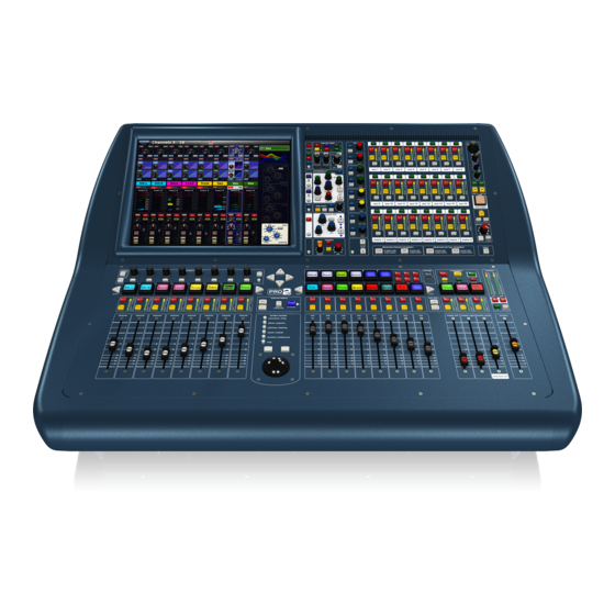
PRO2 (left) and PRO2C control centres The PRO2 Control Centre is built on a robust Midas steel frame chassis similar to those used for established Midas analogue products. The frame houses two main bays (three on the PRO2) that, collectively, provide the primary mixing needs of the engineer. -
Page 36: Pro2 Control Surface
Chapter 3: About The PRO2 Control Centre PRO2 control surface During show time the functions that require fast access are controlled by control knobs (rotary encoders), pushbutton switches, faders etc. More complex functions that do not require this fast access are controlled via the GUI screen using the trackball and left and right navigational keys. - Page 37 EXTEND button which allows the channel fader to extend over the usual mix faders (temporarily overriding them). The additional input bay of the PRO2 (16-channel version) operates in an identical manner to this area. Navigation zone For GUI screen navigation via a trackball. Includes a screen access panel for direct GUI screen access.
-
Page 38: Connections
• External USB keyboard: You can plug a USB keyboard into one of the USB connectors on the rear panel of the PRO2. • MIDI: Standard 5-pin connectors are housed in the rear panel of the PRO2 for use as MIDI in, out and through ports. - Page 39 External interfaces • USB: Two USB ports are provided on the rear panel of the PRO2. In addition, there is a USB port on the control surface (storage section) for removable storage via a USB memory stick. • DVI ports for external monitor: The control centre has a screen output DVI connector on the rear panel of the PRO2 for connecting an external monitor.
- Page 40 Chapter 3: About The PRO2 Control Centre PRO2 Live Audio System Owner’s Manual...
-
Page 41: Getting Started
Getting Started Volume 1: PRO2 Live Audio System Owner’s Manual... -
Page 43: Chapter 4: Setting Up The System
“IMPORTANT SAFETY INSTRUCTIONS” at the front of this manual. This chapter shows you how to set up an PRO2 Live Audio System to its default configuration. Note: If you want to set up the PRO2 Live Audio System using a configuration other than the default, please contact Midas Technical Support for details. -
Page 44: Optional Equipment
Degradation of up to 60dB at a frequency corresponding to the modulation signal may be experienced under extreme conditions (3V/m, 90% modulation). Optional equipment Unless advised otherwise, optional equipment must only be installed by service personnel and in accordance with the appropriate assembly and usage regulations. PRO2 Live Audio System Owner’s Manual... -
Page 45: Making Up A Rack
Note: Never combine units in the same rack that have been designed for a ventilation air flow direction other than that for the PRO2 units. To avoid this, we recommend that any non-PRO2 units are housed separately. -
Page 46: Connecting Up
Pin 1 connected to the cable screen. All Jack connector shells should be connected to the cable screen. For more information, see the PRO2 Live Audio System - Set Up Guide (part number DOC04-DL2SUG1). Audio connections This section gives details of the audio connections of the PRO2 Control Centre. -
Page 47: Other Connections
Connecting up Other connections The section gives details of the other PRO2 Control Centre interconnections. Description Example Pinouts Example of socket 4-pin, male XLR 1 = N/A chassis connector(s) 2 = N/A on the rear panel for 3 = ground... -
Page 48: Powering The Pro2 System
PRO2 system has been completed. After all PRO2 system interconnections have been made, start up the PRO2 system: Make sure that all of the PRO2 system equipment is switched off, that is, the PRO2 Live Audio System, speaker sub-system and DL251 Audio System I/O. -
Page 49: Switching The Pro2 Control Centre On/Off
The control centre will power up; the GUI will display the default screens and all the controls will be set to default. You are now ready to start using the PRO2 control centre. >> To switch off the PRO2 Control Centre Make sure you have saved any shows, scenes or settings you require (see “Saving your show files to a USB memory stick”... - Page 50 Chapter 4: Setting Up The System PRO2 Live Audio System Owner’s Manual...
-
Page 51: Basic Operation
Basic Operation Volume 2: Of The PRO2 PRO2 Live Audio System Owner’s Manual... -
Page 53: Chapter 5: Before You Start
(stored in the computer memory of the PRO2). To make sure there are no hidden surprises, such as a reverb send left from a previous mix, we recommend that you view unused parameters at various times during a mix. - Page 54 • Saving a show copies the show file onto the internal solid-state disk of the PRO2. This provides you with a ‘permanent’ copy, provided you shut down the system properly as detailed in the following section.
-
Page 55: Working With The Pro2 Control Centre
PRO2, particularly those for navigation and GUI operation. As you will probably have had experience on analogue consoles, you will already be familiar with most of the PRO2 controls and their operation. -
Page 56: About Gui Operation
PRO2 and provide extra functionality. For information on how to operate the GUI (for example, using click and drag, using the screen access buttons), see PRO2 GUI Navigation in the PRO2 Live Audio System Quick Start Guide. -
Page 57: Status Bar
The detail area can show an output, Detail while the main area displays input area channel overviews, and vice versa. Main area You can navigate the eight channel faders to show output channel overviews. PRO2 Live Audio System Owner’s Manual... -
Page 58: Parameter Values Displayed On Touch
Chapter 6: Working With The PRO2 Control Centre Parameter values displayed on touch You can configure the PRO2 (see “Setting the user interface preferences” on page 209) so that the GUI displays the current value (and dimension) of the control being adjusted. - Page 59 Also, each window has a close (X) button at its upper-right corner. >> To close a window Do one of the following: • To acknowledge your changes, click OK. PRO2 Live Audio System Owner’s Manual...
-
Page 60: Using The Gui Menu
Chapter 6: Working With The PRO2 Control Centre • To cancel your changes, click CANCEL. • Click “(X)” at the upper-right corner of the window. >> To move a window Use drag, by clicking on the window’s blue bar (top) and dragging the window where you want it. -
Page 61: Chapter 7: Navigation
Chapter 7: Navigation This chapter introduces you to PRO2 navigation and shows you how to use the navigational tools of the PRO2 Control Centre to navigate its channels, groups and buses. For information on other types of PRO2 navigation, refer to the following: •... -
Page 62: Advanced Channel Navigation
• Assigning VCA groups to the mix bay • Assigning outputs to the mix bay For more information, see the PRO2 Live Audio System Quick Start Guide. Advanced channel navigation The console’s advanced navigation mode switches can be locked out via the GUI menu... - Page 63 Then click the User tab to open the Preferences User screen (right). In the User Interface section, click the Hide Unassigned Channels when Flipped selection box to tick it. The console is now ready for collapsed flip operation. PRO2 Live Audio System Owner’s Manual...
-
Page 64: About Gui Navigation
While the control surface provides instant, one-button access to many controls, the GUI provides an alternative way of navigating the PRO2 and offers some unique methods of its own. The GUI menu gives you access to all of the screens that you will need and you can even navigate backwards/forwards through the screens that you have recently opened. -
Page 65: Chapter 8: Patching
This chapter describes the patching function of the PRO2. Introduction The patching function is fundamental to PRO2 operation as, until the I/Os have been correctly patched, you won’t get any audio. Patching is done entirely at the Patching screen, which is an option in the GUI menu. This screen lets you carry out all the... - Page 66 • Press the routing / metering button in the navigation zone. • At the appropriate GUI screen, click the src (source) or dest (destination) button. The Patching screen will open at the appropriate tab/configuration window. PRO2 Live Audio System Owner’s Manual...
- Page 67 Exercise great caution when using this function. Observe the warning that appears after clicking this button. CONFIG Opens the AES50 Device Configuration window, from where you can configure the device (see “The AES50 Device Configuration window” on page 62). PRO2 Live Audio System Owner’s Manual...
- Page 68 Stage I/O tab — From The Stage I/O tab contains the devices fitted in the stage racks. For a typical display, see Figure 2 “A typical Patching screen display” on page 48. PRO2 Live Audio System Owner’s Manual...
- Page 69 For example, to an effect or to provide a way out of the DL251/DL252 Audio System I/O via a line I/O unit. This tab can also be accessed directly via the dest button in the direct output section of the input channels. PRO2 Live Audio System Owner’s Manual...
- Page 70 The Ins. Sends (Insert Sends) tab allows any of the input and output channels to be routed, primarily to an effects device. Effects tab — From The Effects tab allows patching from any of the effects. PRO2 Live Audio System Owner’s Manual...
- Page 71 Inputs tab — To The Inputs tab allows sources to be routed to the input channels and returns. This tab is also accessed from the src button in the configuration section of the input channels. PRO2 Live Audio System Owner’s Manual...
- Page 72 The Ins. Ret. (Insert Return) tab allows insert returns to be patched to any of the inputs and outputs. This screen is also accessed directly via the src button in the insert section of both the input and output channels. PRO2 Live Audio System Owner’s Manual...
- Page 73 Equivalent on the Monitors screen Talk Input Source talk input Talkback Input Source talkback input Ext Input Source L external input L Ext Input Source R external input R PFL Direct Input Source pfl direct input PRO2 Live Audio System Owner’s Manual...
- Page 74 Patching screen open, but the appropriate tab in the From/To section will be open as well. For a full list of patching routing on the PRO2, see “Navigating to the Patching screen” on page 16. About the devices on the I/O tabs The following devices will, if selected (see “Setting up the I/O rack device(s)”...
- Page 75 DL351 Modular I/O. The others are “DL351B”, “DL351C” and “Dl351D”. For more information, go to our website www.midasconsoles.com. DL351B See “DL351A”. DL351C See “DL351A”. None-Unknown Selects no device. DL351D See “DL351A”. This is not displayed. PRO2 Live Audio System Owner’s Manual...
- Page 76 I/O devices. Item Description Unit type. Unit ID number. Unit name and PRO2-assigned unit number. ‘Spanner’ button, opens the device configuration window (see “Configuring the devices” on page 60). XLR patch connector, which is male or female, depending on section location.
-
Page 77: Patching Tooltips
List of selected sources still to be patched. Contains channel and device ID information. The source patch connector currently waiting to be patched. Once patched, this will disappear from the list and the one immediately above will become the next available. PRO2 Live Audio System Owner’s Manual... -
Page 78: About The Patching Procedure
• Repeating for the other cards/channel ranges of the device. • Repeating for the other devices. • Closing the device’s configuration window. Note: The parameters available for a device are dependent on its type. PRO2 Live Audio System Owner’s Manual... - Page 79 For example, the FOH line I/O device (ID11) connected to port 2. From the drop-down list at the upper-right corner of the window, choose the card/channel. For example, the “AES/EBU Card”. PRO2 Live Audio System Owner’s Manual...
-
Page 80: Setting Up The I/O Rack Device(S)
DL351) from which you can select the card that is actually fitted in the physical unit. The positions of the drop-down lists are relative to the card positions in the physical unit. OK button, closes the AES50 Device Configuration window. PRO2 Live Audio System Owner’s Manual... - Page 81 Select the device from the list in the left of the AES50 Device Configuration window. Then, choose “None-Unknown” in the In the device type: drop-down list. For more information, see “To add a device or change its set up” above. PRO2 Live Audio System Owner’s Manual...
-
Page 82: How To Patch
From section): • Select the patch connector ( during a single patching operation. • Patch the patch connector ( during either a sequence or an automatic patching operation. Otherwise, this has no effect. PRO2 Live Audio System Owner’s Manual... - Page 83 >> To remove the patches from all selected patch connectors Click CLEAR SEL. >> To clear a block of patch connectors Click NONE. In the From section, select the patch connectors you want to unpatch. Click CLEAR SEL. Click NONE. PRO2 Live Audio System Owner’s Manual...
- Page 84 • Sources are selected in blocks (see “To select a block of patch connectors in the From section” on page 65). • You can only select one block of sources. • Destinations are restricted to a single type. PRO2 Live Audio System Owner’s Manual...
- Page 85 (shown right) will appear. Heed the warning and do one of the following: • If you want to clear all current patching, click OK. • To cancel the clear operation and close the WARNING, click CANCEL. PRO2 Live Audio System Owner’s Manual...
- Page 86 Chapter 8: Patching PRO2 Live Audio System Owner’s Manual...
-
Page 87: Chapter 9: Basic Operation
Setting a mic amplifier’s input gain The PRO2 Control Centre has two input gains per channel, one is the remote gain for the analogue mic pre (stage box gain) and the other is the digital trim (console gain). -
Page 88: Setting The High And Low Pass Filters
Adjust the gain trim control knob to set the stage box input gain. Range is shown on the GUI. Adjust level to suit the Midas pre-amp characteristic; a suitable level could be one that only just illuminates the yellow LEDs. Drive the mic amps for that ‘Midas colouration’... -
Page 89: Input Equalisation (E Zone)
Alternatively, you can click the desired SHAPE button in the GUI channel strip. Note: bright and deep use psychoacoustic phenomena to generate steep slopes that sound natural. These filters are called “minimum harmonic disruption filters”. PRO2 Live Audio System Owner’s Manual... -
Page 90: Input Dynamics Processing (D Zone)
250. You can set up a limiter by using a high threshold and a steep ratio (greater than 5:1). Press KNEE to audition the different algorithms (hard knee, medium knee Hard and soft knee). The effects on the Medium signal are shown right. Soft PRO2 Live Audio System Owner’s Manual... -
Page 91: Output Processing
The outputs (except returns) have five compressor modes, which include all of the ones on the input channels, but with the addition of a shimmer mode. The returns have the same compressor modes as those of the input channels. PRO2 Live Audio System Owner’s Manual... -
Page 92: Using Vca/Population Groups
To quickly see which channels are in a particular VCA group, press its SOLO button on/off. Monitor this action on the Console Overview screen. Only the SOLO buttons of channels that are group members will be affected. PRO2 Live Audio System Owner’s Manual... - Page 93 >> To change the colour of all of a group’s members to match that of its VCA/POPulation group Click the fill icon of the group. For example, if the colour of the VCA/POPulation is blue all of its group members will now be blue. PRO2 Live Audio System Owner’s Manual...
-
Page 94: Setting Up A Mix
Chapter 9: Basic Operation Setting up a mix The PRO2 has 24 configurable mix buses, each of which can be aux mixes, subgroups or mix minus. The aux mixes can also be set up as stereo pairs (restricted to like- coloured buses) or mono. - Page 95 • In the GUI channel strip, click dest (shown right). This will open the Patching screen and the appropriate tab. • In the Patching screen, route the aux/matrix. For information on patching, see Chapter 8 "Patching" on page 47. PRO2 Live Audio System Owner’s Manual...
- Page 96 For details of the parameters that are stereo linked, see Appendix J "Parameters Affected By Stereo Linking" on page 461. PRO2 Live Audio System Owner’s Manual...
-
Page 97: Setting Up The Effects Rack
Klark Teknik Square ONE Dynamics, which is an 8-channel analogue dynamics processor. Used for the precise manipulation of compression parameters, it also includes gating for creative and corrective applications, and channel linking for stereo/multi-channel operation. PRO2 Live Audio System Owner’s Manual... - Page 98 / graphics screen access button in the navigation zone. Choose the rack position and click within it. In the effect’s window, click Change Device Type. In the Change Device Type window, select the device type. For example, “Phaser”. Click OK. PRO2 Live Audio System Owner’s Manual...
-
Page 99: Simple Routing To Master Stereo Outputs
(upper-left corner of effect). You can do this via the GUI or from the I zone using the output bay GUI (see “PRO2 control surface” on page 18). Click OK to exit. The new effect will appear in the effects rack. -
Page 100: Automation
Chapter 9: Basic Operation Automation PRO2 automation is managed from the Automation screen of the GUI menu, with support from the automation section of the control surface (output bay). The Automation screen (a typical example is shown right) has the following functions and features: •... - Page 101 Click OK. The file will start loading and the window will close. When the file has finished loading, its name will appear in the show file name field (to the right of the SAVE AS button). PRO2 Live Audio System Owner’s Manual...
- Page 102 • NOW (yellow) — the most recently loaded scene. • NEXT (green) — the next available ‘non-empty’ scene. The automation section in the output bay (see “PRO2 control surface” on page 18) supports the Automation screen by providing controls for scene navigation, selection and management.
- Page 103 Click OK. Additional control — managing events You can use the MIDI or GPIO functions of the PRO2 to control the parameters of an external device (outgoing), and conversely you can use an external device to control the PRO2 (incoming). Also, by using the PRO2’s unique ‘internal’ event option, you can trigger events from within the showfile itself.
-
Page 104: Configuring The Inputs And Outputs
Naming Sheet. Alternatively, choose home Mix & Outputs Naming Sheet. • In the navigation zone, press the inputs/outputs screen access button once to open the Input Sheet screen or twice to open the Output Sheet screen. PRO2 Live Audio System Owner’s Manual... -
Page 105: Using Copy And Paste
• Channel names are not copied. • Compressor and gate side chain listen cannot be copied. For details of the channel parameters that are copied across, see Appendix I "Parameters Affected By Copy And Paste" on page 431. PRO2 Live Audio System Owner’s Manual... -
Page 106: User Library (Presets)
Chapter 9: Basic Operation User library (presets) The PRO2 has a user library where you can store settings, such as for the EQ or even the whole channel. For example, you may wish to store the EQ settings of a singer who may be called upon to perform during a future show. -
Page 107: Surround Panning
Surround panning Surround panning In addition to stereo and left-centre- right (LCR) panning, PRO2 has three Position surround panning modes: quad; left, cursor centre, right and surround (LCRS); and 5.1 surround. To help you visualise the Sound surround panning envelope, the... -
Page 108: Area B Operation
General). Area B operation You can configure the PRO2 Control Centre to have an area B, where any three channels of your choice populate the master channel strips and are totally independent of the ones assigned to the channel/mix faders. This mode of operation is enabled on selecting a VCA/POPulation group that is configured for area B operation. -
Page 109: Saving Your Show Files To A Usb Memory Stick
(USB memory stick). This provides a valuable back up should the show file stored in the internal memory of the PRO2 be lost, for example, due to inadvertent deletion. You can also load show files onto the PRO2 from the same storage device. -
Page 110: External Aes50 Synchronisation
The procedure is similar to the export procedure, as detailed in “To save (export) a show file to a USB memory stick” above, but select the file to be imported to the PRO2 from the Removable Storage panel and then click IMPORT. -
Page 111: Advanced Operation And Features
Advanced Volume 3: Operation And Features PRO2 Live Audio System Owner’s Manual... -
Page 113: Chapter 10: Stereo Linking
The diagram right gives an example of two linked channels (auxes 15 and 16). By default, all channels of the PRO2 are unpaired (mono). When paired, the controls for each signal path act simultaneously on both the left and right signal paths. -
Page 114: Changing The Linking Options
GUI channel strip, and then click the st. linking options button in the GUI channel strip. In the Stereo Linking Options window, select the controls that you want to be linked across the channel pair. Click CLOSE. PRO2 Live Audio System Owner’s Manual... -
Page 115: Chapter 11: Panning
Chapter 11: Panning The PRO2 has two main types of panning mode, default and surround. The default mode comprises stereo and LCR panning formats, and only uses the channels for the front loudspeakers, while the surround mode includes channels for the rear surround loudspeakers. -
Page 116: Sis™ (Lcr) Mode
Chapter 11: Panning SIS™ (LCR) mode The MIDAS SIS™, which is used for left-centre-right (LCR) loudspeaker systems, configures the channel for LCR mixing. The SIS switch activates the spatial imaging system, which uses the SIS image control knob to modify pan control knob operation so as to place the channel within a three-speaker system. - Page 117 SIS image control knob centred (equal power) With both the SIS image and pan Centre control knobs centred, the signal is routed to all three speakers with Right Left equal power. PRO2 Live Audio System Owner’s Manual...
-
Page 118: Surround Panning
Chapter 11: Panning Surround panning When the PRO2 is configured to operate in one of the surround panning modes, the spatial diagram that appears in the GUI channel strip gives you a visual representation of the sound image in relation to the speakers. -
Page 119: Speaker Placement
= 30° for stereo (LR) and 45° for all other panning modes Listening distance 45° Lr/Ls Rr/Rs Note: LCRS has a mono surround channel, which is often fed to two rear ‘satellite’ speakers. PRO2 Live Audio System Owner’s Manual... - Page 120 Chapter 11: Panning PRO2 Live Audio System Owner’s Manual...
-
Page 121: Chapter 12: Soloing
• Pressing PFL (solo a/b) on changes the point at which the soloed signal is taken from, that is, from post-fader to pre-fader. • Soloing inputs and outputs: With solo A off there is no solo in operation. PRO2 Live Audio System Owner’s Manual... -
Page 122: Solo B
B on, solo goes to the B bus and with solo B off, solo goes to the A bus. Solo B has separate ADD, CLEAR and PFL controls that, in broadcast mode, can be used to control those functions independently of solo A. PRO2 Live Audio System Owner’s Manual... -
Page 123: Solo Hierarchy
A output and unlinks the ADD, CLEAR and PFL controls in the monitor section. This allows the main program material to be monitored at the same time as something soloed on the solo B bus. PRO2 Live Audio System Owner’s Manual... - Page 124 Chapter 12: Soloing PRO2 Live Audio System Owner’s Manual...
-
Page 125: Chapter 13: Muting
A bus. For SIP muting, channels must be input channels set up to solo the solo A bus. All of the above mute activation methods, except VCAs, mute the channel outputs and update the channel mute status indicator. PRO2 Live Audio System Owner’s Manual... - Page 126 Chapter 13: Muting PRO2 Live Audio System Owner’s Manual...
-
Page 127: Chapter 14: Monitors And Communications
Chapter 14: Monitors And Communications This chapter describes the monitoring and communications functions of the PRO2. Monitors (A and B) To match the two-bus solo system there are two monitor outputs, A and B, which control their respective output levels. These are controlled from the monitor section on the master bay (see Figure 9 “Monitor A and B strips”... - Page 128 A to fader. Fader for control of monitor A or B speaker level from -∞ to +10. left and right meters for monitor a (GUI only). left and right meters for monitor b (GUI only). PRO2 Live Audio System Owner’s Manual...
- Page 129 0ms to 500ms. Up/down spin Provide finer adjustment of the monitor output signal buttons delay. ON switch Switches the delay on/off. Two delay value Show the current delay value in milliseconds (ms) fields and metres (m). PRO2 Live Audio System Owner’s Manual...
-
Page 130: Solo System
You can protect a channel from this function by switching on its mute safe (see “Safes” on page 285). PRO2 Live Audio System Owner’s Manual... - Page 131 Left monitor signal is routed to both of the monitor speaker outputs. PRO2 Live Audio System Owner’s Manual...
- Page 132 When input solo is cancelled, output solo or VCA solos will return. • CLEAR switch, illuminates when a solo switch is active in its monitor section and, when pressed, clears any solo switches in that section. PRO2 Live Audio System Owner’s Manual...
- Page 133 The following four sections in the Monitors screen allow you to patch the solo system signals. • talkback input • pfl direct input • afl direct input left • afl direct input right For routing details, see Table 25 “Navigating to the Patching screen” on page 418. PRO2 Live Audio System Owner’s Manual...
-
Page 134: Signal Generator
(see “Talk osc/routing” on page 117). level control knob Gives continuous adjustment of signal generator peak output signals from off (4) to +10dB. The OSC switches (internal and external) are the talk routing switches. PRO2 Live Audio System Owner’s Manual... -
Page 135: Talk Osc/Routing
Make sure either one or both of the ‘internal’ buttons, that is, the TALK (internal) button in the talk mic section and the OSC (internal) button in the signal generator section, are on. Click the desired talk/oscillator routing button. PRO2 Live Audio System Owner’s Manual... -
Page 136: Talk Mic
(see “Talk osc/routing” on page 117). TALK/[TLK] This talk external switch connects the talk mic output (external) switch to the talk external output XLR. level control knob Gives continuous adjustment to the post-limiter signal from off (4) to +10dB. PRO2 Live Audio System Owner’s Manual... - Page 137 The external talkback input is a mic/line input at the stage end of the system that, when enabled in the monitor section (see “Monitor output (A and B)” on page 113), can mix onto the local monitor outputs. PRO2 Live Audio System Owner’s Manual...
- Page 138 Chapter 14: Monitors And Communications PRO2 Live Audio System Owner’s Manual...
-
Page 139: Graphic Equaliser (Geq)
Chapter 15: Graphic Equaliser (GEQ) This chapter describes the internal GEQs of the PRO Series. Initially, it explains how to use the PRO2 Control Centre to configure and operate the GEQs and then details all of their available control functions. - Page 140 • In the navigation zone, press the effects/graphics access button twice. >> To open a GEQ rack Do one of the following: • In the Graphic EQs screen, click on the desired unit. • Press ENTER in the assignable controls section. PRO2 Live Audio System Owner’s Manual...
-
Page 141: About The Geq Window
124. Drop-down list For selecting the source of the GEQ. >> To open a GEQ unit window In the Graphic EQs screen, click on a non-control area of the unit you want. PRO2 Live Audio System Owner’s Manual... -
Page 142: Geq Front Panel Features
High pass filter Adjusts the cut off frequency, which is continuously control knob variable from 20Hz to 500Hz. Low pass filter Adjusts the cut off frequency, which is continuously control knob variable from 2kHz to 20kHz. PRO2 Live Audio System Owner’s Manual... -
Page 143: Configuring The Number Of Geqs (And Effects)
Configuring the number of GEQs (and effects) GEQ (and effects) configuration is a GUI-only operation. We recommend that you configure the number of GEQs and effects before you start using the PRO2 Control Centre. >> To configure the PRO2 Control Centre with the number of GEQs and effects... -
Page 144: Copying Settings Between Geqs
Chapter 15: Graphic Equaliser (GEQ) Typical example of how the Graphic EQs and Effects will look screens when PRO2 is configured with the 1 Effect - 28 GEQs option. Copying settings between GEQs You can copy and paste all the settings of one GEQ to another. -
Page 145: Chapter 16: Internal Effects
Chapter 16: Internal Effects This chapter describes the internal effects of the PRO2. Initially, it explains how to use the PRO2 Control Centre to operate the effects and then details all of their available control functions and their use. Overview of the internal effects The Effects screen manages up to six user-assignable effects devices, which are a ‘bundle’... -
Page 146: About The Effect Window
LOAD PRESET User library function button (see Chapter 24 "User button Libraries (Presets)" on page 235). CLOSE button Closes the effect window. assignable See Chapter 19 "Assignable Controls (I Zone)" on controls panel page 187. PRO2 Live Audio System Owner’s Manual... -
Page 147: Working With The Effects
For details of each effect type, refer to its section in this chapter. For information on presets, see Chapter 24 "User Libraries (Presets)" on page 235. PRO2 Live Audio System Owner’s Manual... -
Page 148: Delay Effect
Range of both is -12 to +12, with 0 at top dead centre. Rate control knob Adjusts rate of delay modulation. Range is between 0.001Hz and 10Hz, with 0.7Hz at top dead centre. PRO2 Live Audio System Owner’s Manual... - Page 149 Adjusts the tempo in tempo mode. Range is from 60 knob to 240 beats per minute (bpm). Tap button For manually tapping the tempo once the unit is in BPM Sync (TAP TEMPO) mode. PRO2 Live Audio System Owner’s Manual...
-
Page 150: Virtual Dn780 Reverb Effect
List of algorithms These algorithms emulate the ones on the original and algorithm DN780. Use the select button to scroll through the select button list to select the one you want. PRO2 Live Audio System Owner’s Manual... - Page 151 The parameter controls give accurate adjustment of all reverberation parameters and allow the engineer to create unique acoustic environments of virtually any type. For more information on the Klark Teknik DN780, see Appendix D “Klark Teknik DN780 Reverb”. PRO2 Live Audio System Owner’s Manual...
-
Page 152: Flanger Effect
1kHz to 20kHz, with 10kHz at top dead centre. LF control knob Damping section control for adjusting the low frequency (kHz) tuning of flanger feedback. Range is 20Hz to 1kHz, with 140Hz at top dead centre. PRO2 Live Audio System Owner’s Manual... -
Page 153: Phaser Effect
(in dB). Range is from -12dB to +12dB with 0dB at top dead centre. gain control knob Adjusts the signal level (dB). Range is from -20dB to +20dB, with 0dB at top dead centre. PRO2 Live Audio System Owner’s Manual... - Page 154 Two rows of 15 green LEDs — one row each for L (left) and R (right) — comprise the output meters. Number of all pass Displays the number of all pass stages, selected by stages the STAGES button. PRO2 Live Audio System Owner’s Manual...
-
Page 155: Pitch Shifter Effect
Boosts/attenuates low frequencies. Range is from knob -12 to +12, with 0 at top dead centre. MIX control knob Controls the balance between dry signal and effect. Range is from 0 to 100, with 50 at top dead centre. PRO2 Live Audio System Owner’s Manual... -
Page 156: Sq1 Dynamics Effect
SQ1 Dynamics effect For information on the Klark Teknik Square One Dynamics, refer to its Operator Manual (part number DOC02-SQ1DYNAMIC). Front panel of the SQ1 dynamics effect PRO2 Live Audio System Owner’s Manual... -
Page 157: 3-Band Compressor Effect
Sets the crossover point between the Lo and Mid control knob compressors. Range is from 40Hz to 1kHz. Hi Mid Freq Sets the crossover point between the Mid and Hi control knob compressors. Range is from 640Hz to 16kHz. PRO2 Live Audio System Owner’s Manual... -
Page 158: Dynamic Eq
• Two chains of stereo 2-band processing. Band n Band n Band n Band n • Four chains of stereo single-band Band 1 processing. Band 2 Band 3 Band 4 Front panel of the dynamic EQ effect PRO2 Live Audio System Owner’s Manual... - Page 159 (FREQ) and width (WIDTH) controls. Band I/O Shows the audio routing path between inputs, outputs and the four EQ bands. PRO2 Live Audio System Owner’s Manual...
- Page 160 Below Threshold Compression Below Threshold Expansion ( Below = on, Ratio = comp ) ( Below = on, Ratio = exp ) Output Output Level Level Input Input threshold threshold Level Level Figure 10: Transfer characteristics PRO2 Live Audio System Owner’s Manual...
-
Page 161: Chapter 17: Control Groups
For information on group selection and navigation, see Chapter 6 "Working With The PRO2 Control Centre" on page 37 and Chapter 7 "Navigation" on page 43. For details of VCA/POPulation group configuration and operation, see “Using VCA/ POPulation groups”... - Page 162 A section of the control centre. It is used to monitor the VCA master faders by creating a mix on the solo buses, which consists of all input channels and audio mix groups that are assigned to control from corresponding VCA masters. PRO2 Live Audio System Owner’s Manual...
- Page 163 VCA group ID, fixed and user-configured name of group. MTE button for selecting mute safe. Integral LED illuminates when the button is switched on. FDR button for selecting fader safe. Integral LED illuminates when the button is switched on. PRO2 Live Audio System Owner’s Manual...
-
Page 164: Mca Groups
The GUI shows the MCA level associated with the selected mix, as shown in the lower-right corner of the screen. Selecting a VCA shows the VCA level. For information on how to use MCAs, see the PRO2 Live Audio System Quick Start Guide. PRO2 Live Audio System... -
Page 165: Auto-Mute (Mute) Groups
• Recalling a scene that assigns an already active auto-mute. An auto-mute off can happen because of: • Deactivating all of the assigned auto-mutes. • Unassigning all of the active auto-mutes. • Recalling a scene that de-assigns all of the active auto-mutes. PRO2 Live Audio System Owner’s Manual... -
Page 166: About The Control Group Screens
The group management section of each control group screen has two main panels that, with the aid of the ADD and REMOVE buttons, let you choose group members. Typical management section of control group screen PRO2 Live Audio System Owner’s Manual... - Page 167 If you want to remove any members from the group, click the channels that you want to remove from the group (group member panel). Then, click REMOVE. The channels are moved back to their respective lists. PRO2 Live Audio System Owner’s Manual...
-
Page 168: Configuring The Groups
>> To open the Group Sheet screen At the GUI, choose home Control Groups Group Sheet. PRO2 Live Audio System Owner’s Manual... -
Page 169: Chapter 18: Copy And Paste
Chapter 18: Copy And Paste The PRO2 has a number of copy and paste features that make it easy to copy useful settings to other areas. You can copy and paste the following: • Detail areas across channels — see “Using copy and paste” on page 87. - Page 170 Chapter 18: Copy And Paste PRO2 Live Audio System Owner’s Manual...
-
Page 171: Chapter 19: Assignable Controls
• Operate the controls of an internal rack unit (see “Controlling an internal effect/GEQ” on page 157). User-assignable controls Navigational buttons Set of assignable controls Quick access button Figure 11: The assignable controls section on the control surface PRO2 Live Audio System Owner’s Manual... -
Page 172: Operating The Channel Fader Assignments
ALT button changes the button assignment within a detail area Diagram showing the detail area control assignments of the assignment controls PRO2 Live Audio System Owner’s Manual... -
Page 173: Controlling A Rotary Control
Controlling a rotary control Controlling a rotary control An important function of the PRO2 is one that lets you operate any of the control knob functions on the control surface, such as gain trim, compressor/gate threshold and level, and even any of the internal effects (but not the GEQs), from the assignable controls section. - Page 174 Tap the assign/unassign button of the assigned control (just as you would the Tap button of the effect) to achieve the desired tap time. The PRO2 measures the interval between taps. It uses the most recent taps to calculate the average tap time, which is constantly updated according to each subsequent tap.
-
Page 175: Controlling An Internal Effect/Geq
Controlling an internal effect/GEQ Controlling an internal effect/GEQ As the internal effects and GEQs of the PRO2 are primarily GUI-only features, control surface support is provided by the assignable controls section, which lets you operate their parameters using physical controls. - Page 176 GEQ” on page 159). Don’t forget that you can operate the selected effect or GEQ in their respective rack unit view (for example, the Effects screen shown right) via the control surface or GUI. PRO2 Live Audio System Owner’s Manual...
-
Page 177: Controlling A Geq
GEQ, and lets you adjust a group of GEQ faders simultaneously by the same amount. Overview display Fader group ID numbers (encircled) Figure 13: Fader group control knob assignments in the overview display of the Graphic EQs screen PRO2 Live Audio System Owner’s Manual... - Page 178 The right navigation arrow button opens the GEQs control panel (far right). Zoom displays Overview display Figure 14: I zone LCD button assignments in the overview display PRO2 Live Audio System Owner’s Manual...
-
Page 179: Chapter 20: Scenes And Shows
The automation system of the PRO2 can store and recall up to 1000 scenes, each one being a snapshot of the control centre’s settings at the instant the scene was created. -
Page 180: Automation Controls
Opens the Store Scene window (see “To create a SCENE] button new scene using the current settings” on page 59) and lets you store the current settings to the currently selected scene. PRO2 Live Audio System Owner’s Manual... -
Page 181: Automation Screen
• Show Editor: Opens the Show Editor window. • Invert Selection: Any scenes that have been ‘checked’ (that is, their check box in the Edit column contains an “X”) become unchecked, and vice versa. PRO2 Live Audio System Owner’s Manual... -
Page 182: Scenes
See “Editing scene properties” on page 168. Scene panel Contains scene number, title and notes pertaining to the ‘now’ scene. Show information See “Date and time” on page 166 and “Automation panel controls” on page 162. PRO2 Live Audio System Owner’s Manual... -
Page 183: Scene Contents
• Gains are set to 0dB. • All levels are at minus infinity (- ) dB. • All faders are at minus infinity (- ) dB — except VCA faders, which remain at 0dB. PRO2 Live Audio System Owner’s Manual... -
Page 184: Date And Time
Time column Displays the time before an event is triggered. A blue countdown time bar shows the time remaining. Name column Title of scene/point scene or name of event. Notes column Scene notes. PRO2 Live Audio System Owner’s Manual... - Page 185 >> To close the point scenes of a scene/point scene Select the scene/point scene and do one of the following: • Click UNEXPAND. • Right-click the scene to open the right-click menu. Then, choose Un-Expand. PRO2 Live Audio System Owner’s Manual...
-
Page 186: Editing Scene Properties
Open the Edit Scene Properties window of the desired scene, and then click the lock box to place a red cross inside it. After you close the window, a lock symbol will appear in the scene’s Lock column. PRO2 Live Audio System Owner’s Manual... -
Page 187: Adding A New Scene
Do one of the following: • Select the scene and then click DELETE. • Right-click on the scene and then choose Delete from the right-click menu. In the message window (shown right), click OK. PRO2 Live Audio System Owner’s Manual... -
Page 188: Changing The Order Of The Scenes
>> To override the safed parameters (selected in store scope) for every scene At a GUI screen, choose home Preferences General and then click the User tab to open the Preferences User screen. Then, select the Overwrite “Safe” parameters option in the On Scene Store section. PRO2 Live Audio System Owner’s Manual... -
Page 189: Using Patching In Automation
>> To reduce the scene view (zoom out) In the Automation screen, click the down (bottom) Zoom List spin button. The diagram right shows a typical Automation screen at minimum zoom. PRO2 Live Audio System Owner’s Manual... -
Page 190: Show Files
(see “To save a show or create a new one from the current settings” on page 83). STORE SCENE For details, see “To create a new scene using the current settings” on page 84. SHOW EDITOR For details, see “Show editor” on page 86. PRO2 Live Audio System Owner’s Manual... -
Page 191: Rehearsals
Rehearsals Managing show files on the Files screen Show files can be transferred between the PRO2 and an external USB device, such as a USB memory stick. This allows you to backup and archive your show files, so none will be lost, and also transfer them to other PRO2s. -
Page 192: Safes
Safes are intended for emergency use only and are not to be confused with scope (see Chapter 21 "Scope (Automation)" on page 177). PRO2 safes prevent certain controls from being recalled with a scene. Safe activation and status are provided on both the control surface (channel safes section) and the GUI (Hardware Safe screen). - Page 193 • Use the appropriate button in the channel safes section with the appropriate channel assigned to the control surface. • At the GUI’s VCA Groups screen, click the desired safe button. PRO2 Live Audio System Owner’s Manual...
- Page 194 Chapter 20: Scenes And Shows (Automation) PRO2 Live Audio System Owner’s Manual...
-
Page 195: Scope (Automation)
Chapter 21: Scope (Automation) This chapter shows you how to use the scope feature of PRO2 automation to include/exclude specific parameters on scene store/recall. Although scope has two functions, recall and store, the emphasis in this chapter is on recall scope, which will be the most commonly used of them both. Store scope will only be required in certain circumstances, and even then it must only be used with caution (see “Using store scope”... - Page 196 Area for the assignable effects and GEQs. Output channels Area for the aux sends, matrices, VCAs and masters. Input channels and Area for the inputs and aux returns. groups The Key window, which is opened by clicking the KEY button PRO2 Live Audio System Owner’s Manual...
-
Page 197: Selecting Scope Parameter Sections
The “Assignable Effects” panel lets you choose which effects are ‘out of scene’ on scene recall. For details of the parameters affected by scope, see Appendix K "Parameters Affected By Scope" on page 421. PRO2 Live Audio System Owner’s Manual... - Page 198 All parameter of input channel 5; all the parameter sections in channel 5 are selected (as shown right). If the channel is stereo linked, all of the parameter sections in its paired channel will also be selected. PRO2 Live Audio System Owner’s Manual...
- Page 199 Click ALL. Every parameter section on the Recall Scope screen is selected (as shown right). >> To deselect a parameter section(s) Follow the procedures for selecting parameters, but only click ones that are already selected. PRO2 Live Audio System Owner’s Manual...
- Page 200 All of the buses are selected >> To select/deselect buses In the ‘bus select’ window, do one of the following: • To select/deselect a single bus, click on its icon. • To select/deselect all buses, click All. PRO2 Live Audio System Owner’s Manual...
-
Page 201: Saving Scope Parameters In A Scene
Please use store scope with great care. All of the methods of the recall scope operation, as detailed in this chapter, apply equally to store scope. PRO2 Live Audio System Owner’s Manual... - Page 202 Chapter 21: Scope (Automation) PRO2 Live Audio System Owner’s Manual...
-
Page 203: Events (Automation)
PRO2’s talkback on/off or you can use an external switch or joystick to control the PRO2’s parameters. You can also use the PRO2’s keys and faders to send control signals to an external device. -
Page 204: About The Edit Event Window
Event Parameters section (see the “Programming events” on page 187). CLOSE button, for closing the Edit Event window. Incoming/outgoing selection section, for selecting whether the event is triggered on the PRO2 or on an external device. Text field, for displaying the user-configured event name. Figure 15: Edit Event window PRO2 Live Audio System Owner’s Manual... -
Page 205: Programming Events
In the Event Name section, type in the event name. If you want to skip this event during a rehearsal, select the Disable Event option. To select whether the event occurs on the PRO2 or an external device, click Incoming or Outgoing, respectively. (This is not applicable to internal events.) Select the desired parameters in the When..., Then do this... - Page 206 The trigger is via a specific IO port. Jump Opens a specified scene on the PRO2. Last Opens the last (previous) scene on the PRO2. This scene is the same one that would be opened if you pressed the last button. MIDI TX Selects a MIDI event.
- Page 207 Parameter Description Next Opens the next scene on the PRO2. This scene is the same one that would be opened if you pressed the next button. Opens the ‘now’ scene on the PRO2. This scene is the same one that would be opened if you pressed the now button.
- Page 208 Chapter 22: Events (Automation) PRO2 Live Audio System Owner’s Manual...
-
Page 209: Crossfades (Automation)
Element Description Crossfade Group Opens the Crossfade Groups screen (see Edit button “Crossfade groups” on page 195). Crossfade set up See “Crossfade set up section in the Edit Event section window” on page 193. PRO2 Live Audio System Owner’s Manual... - Page 210 About the crossfade parameters The following diagram shows the PRO2 configured for 5.1 surround mode, which utilises each available parameter option. The presence of the divergence, centre level and LFE level sections are dependent on the currently selected surround mode.
- Page 211 Click anywhere on the line of the graph in the Edit Event window and drag to where the parameters are as desired. Clicking while pressing the left button adjusts the down travel, and doing the same with the right button adjusts the up travel. PRO2 Live Audio System Owner’s Manual...
-
Page 212: How A Crossfade Operates
Progress is shown in real time on the Automation screen. Blue vertical bar Typical crossfade graph in the Automation screen. The blue vertical bar will travel from left to right according to the time elapsed and at the configured crossfade rate. PRO2 Live Audio System Owner’s Manual... -
Page 213: Crossfade Groups
Control Group Member List, which shows the current members of the selected crossfade control group. ALL and NONE buttons. These buttons select all or none of the members in the Control Group Member List, respectively. PRO2 Live Audio System Owner’s Manual... - Page 214 Click OK. The new name will appear in the Control Group List. If you want, you can rename the “example group” crossfade control group. PRO2 Live Audio System Owner’s Manual...
-
Page 215: Global Events
Select the GLOBAL CROSSFADE AND EVENTS scene and do one of the following: • Click ADD CROSSFADE. • From the right-click menu, choose Add Crossfade Event. The crossfade will appear in the GLOBAL CROSSFADE AND EVENTS scene. GLOBAL scene (highlighted in yellow) in the Automation screen PRO2 Live Audio System Owner’s Manual... -
Page 216: Manually Controlling A Crossfade
Pressing this button while the crossfade is paused (by pressing the cancel button), continues the crossfade. ok button Jumps to the end of the crossfade, effectively cancelling the remaining time to the end of the crossfade. PRO2 Live Audio System Owner’s Manual... -
Page 217: User Libraries (Presets)
For a description of each button, see Table 9 “Description of Preset Manager screen function buttons” on page 200. User library name. library author field, displays the name of user library author/creator. Close button, closes the Preset Manager screen. PRO2 Live Audio System Owner’s Manual... - Page 218 Time that preset was created. >> To open/close the Preset Manager screen To open the Preset Manager screen, at the GUI choose home Preset Manager. To close it, Click X at the upper-right corner of screen. PRO2 Live Audio System Owner’s Manual...
-
Page 219: Managing User Libraries
You have the option to overwrite one of the existing preset libraries. Do this by clicking it in the Save File window and then ticking the Overwrite existing? option. Click OK. The new preset library will be selected. PRO2 Live Audio System Owner’s Manual... -
Page 220: Deleting Presets From A User Library
>> To delete a preset from a user library In the Preset Manager screen, click the preset you want to delete. Click Delete. In the “Are you sure you want to delete this preset?” message window, click OK. PRO2 Live Audio System Owner’s Manual... -
Page 221: Chapter 25: File Management
File lists, display the files on their respective storage media. Each list shows the name, size, creation date and type (for example, show and preset) of each file. Information panels give feedback on file management status. PRO2 Live Audio System Owner’s Manual... - Page 222 Copies file selected in Control Surface section to the Removable Storage section, effectively copying it onto the removable device. This provides a useful backup facility. IMPORT Copies the file selected in the Removable Storage section to the Control Surface section (PRO2). PRO2 Live Audio System Owner’s Manual...
-
Page 223: Chapter 26: Using Other Devices With The Pro2
THE SYSTEM. ALWAYS MUTE THE PA AT THE AMPLIFIER/SPEAKER BEFORE CHANGING THE SYNCHRONISATION SOURCE OR MASTER/SLAVE STATUS. You can use an PRO2 together with one or more digital consoles, which can be other Midas digital consoles or indeed any digital console. For example, you can use two PRO2s together in a dual FOH and MON system. -
Page 224: Using An External Usb Mouse
(to the right of the population and mute groups section). Using an external monitor You can plug a monitor in the DVI socket on the rear panel of the PRO2 for viewing what is shown on any GUI screen. PRO2 Live Audio System... -
Page 225: Changing The Preferences
Chapter 27: Changing The Preferences This chapter shows you how to change the user settings of the PRO2 to suit your own preferences and the current working environment. For information on configuring the number of GEQs and effects, see “Configuring the number of GEQs (and effects)”... -
Page 226: Configuring Playback
Checking the build information The lower-right corner of the Configuration tab is predominantly a service-only feature, and shows the current build and host software versions of the PRO2 Control Centre (typically shown right). Using patching in automation The Automate Patching option switches on per-scene automatic routing, and must be used with caution. -
Page 227: Selecting The Surround Mode
Selecting the surround mode The Surround Mode section of the Show tab lets you select the type of surround mode that the PRO2 uses. For information, see “Selecting the surround mode” on page 209 and “Surround panning” on page 100. -
Page 228: Setting The Navigation Mode
Setting the navigation mode The Navigation Mode section of the User tab lets you select one of the three navigation modes of the PRO2. • Normal (FOH) — this default mode sets the control centre to operate using the standard FOH mode of navigation. -
Page 229: Vca Unfolding
VCA unfolding • Aux sends 1-16 and matrices 1-8 (PRO2 only) • Aux Sends 1-16 (PRO2c only) • The sixth POPulation group is pre-populated with: • Matrices 1-8 (PRO2c only) • FX 1-3 are pre-loaded with DN780 Reverb effects • FX 4 is pre-loaded with a Pitch Shifter effect •... -
Page 230: On-Scene Store
• Next Scene Choose this option to go to the next scene when the foot switch is operated. • Tap Tempo Choose this option to use the foot switch to set the tempo. PRO2 Live Audio System Owner’s Manual... -
Page 231: Selecting The Fan Speed
You can change the default name and colour of the input and output channels, groups, internal rack units and GEQs of the PRO2 that appear on the control surface (LCD select buttons) and GUI. This is done via the ‘Sheet’ screen of each item, which is accessible via the GUI menu. - Page 232 Chapter 27: Changing The Preferences PRO2 Live Audio System Owner’s Manual...
-
Page 233: Delay Compensation (Latency)
A time delay is induced in a channel’s signal by placing, for example, an insert or GEQ in its path. This delay affects system latency and can also produce undesirable audio effects. To overcome this the PRO2 incorporates a system of user-configurable delay compensation parameters. These are presented to the user in the form of button-selectable options on the GUI and can be switched on or off to suit the current application. -
Page 234: Geq Compensation
Chapter 28: Delay Compensation (Latency) To avoid the comb filtering effect, the PRO2 insert compensation works by delaying all channels except the ones that have inserts assigned. In practice, the actual delay used for compensation depends on the type of insert (internal/external) and its location (stage/FOH). - Page 235 GEQ with those that do not. If any master or matrix buses have a GEQ inserted, switch this option on to time-align all master and matrix bus outputs. PRO2 Live Audio System Owner’s Manual...
-
Page 236: Monitor Mode (Align With Masters)
Output Latency = 2.38 ms Output Latency = 2.26 ms Aux Send Matrix Channel Channel Input to Aux Output Input to Aux Output Latency = 1.54 ms Latency = 1.5ms Figure 19: Routing via aux buses PRO2 Live Audio System Owner’s Manual... -
Page 237: Zones
Figure 20: Latency for input to aux, master and matrix outputs Zones The PRO2 system can be divided into conceptual ‘zones’, as follows: • System Input Zone: DL251 Audio System I/O or surface analogue/AES3 inputs, which are normally routed to Input channels. These inputs are primary system inputs and the console output latency is measured relative to these inputs. -
Page 238: Masters To Matrix Tap-Off-Point
2.72 ms, as opposed to pre-processing tap-off points, which would produce a latency of 2.38 ms. When Monitor Mode (Align with Masters) is switched on, these figures are 1.79 ms and 2.14 ms, respectively. PRO2 Live Audio System Owner’s Manual... -
Page 239: Typical Configurations
• XLR – AS DI – MAST – XLR • XLR – AR (Input) – MAST – XLR • XLR – IP – MAST – MTX • XLR – IP – AS (With GEQ) – MAST (With GEQ) PRO2 Live Audio System Owner’s Manual... - Page 240 • XLR – AR (Input) – MAST – XLR • XLR – IP – MAST – MTX • XLR – IP – AS – MAST (With GEQ) • XLR – IP – AS – MTX (With GEQ) PRO2 Live Audio System Owner’s Manual...
- Page 241 • XLR – AR (Input) – MTX (With GEQ) – XLR • XLR – AR (Input) – MAST - MTX - XLR • XLR – AR (Input) – MAST - MTX (With GEQ) - XLR PRO2 Live Audio System Owner’s Manual...
- Page 242 • XLR – IP – AS – XLR • XLR – AS DI – AS – XLR • XLR – AR (Input) – MAST – XLR • XLR – AR (Input) – MAST - MTX - XLR PRO2 Live Audio System Owner’s Manual...
- Page 243 Description Volume 4: PRO2 Live Audio System Owner’s Manual...
-
Page 245: Chapter 29: Panel Connections
Chapter 29: Panel Connections This chapter describes the rear and front panels of the PRO2. Rear panel connections The rear panel has two main areas. PRO2 Live Audio System Owner’s Manual... - Page 246 Video sync connector (see “Video sync” on page 232). Foot switch connector (see “Other connections” on page 29). MIDI connectors (see “MIDI” on page 232). Diagnostics connector. This is for service personnel use only. PRO2 Live Audio System Owner’s Manual...
- Page 247 There are two monitor outputs sections (monitor a and monitor b) for the monitor A and B sections, and both have right and left connectors. left right left right Inputs The inputs section has eight input connectors for XLR mic/line inputs. PRO2 Live Audio System Owner’s Manual...
- Page 248 Master outputs The master outputs section has a mono and left and right output connectors for XLR analogue outputs. mono right left Talk out The talk out output connector for a male output XLR. PRO2 Live Audio System Owner’s Manual...
- Page 249 1 & 2 in 3 & 4 out 1 & 2 Talk back The talk back input connector accepts a female input XLR. AES50 audio Six AES50, 24-wide, bi-directional digital audio EtherCon® ports. PRO2 Live Audio System Owner’s Manual...
- Page 250 Video sync The video sync port has an input BNC cable socket for synchronisation with a video device. MIDI The MIDI section has in, out and thru sockets that each accepts a 5-pin DIN connector. PRO2 Live Audio System Owner’s Manual...
- Page 251 Screen output connector (see “Screen output” on page 234). Mains input connectors (see “Mains power connectors” on page 234). Ethernet control A 100Mb/s Ethernet control port (on EtherCon®) lets you connect equipment, such as the Klark Teknik DN9331 Rapide Graphic Controller. PRO2 Live Audio System Owner’s Manual...
- Page 252 A DVI screen output port lets you connect an external monitor so that you can view remotely what is shown on the GUI screen. Mains power connectors Dual redundant power supplies each accept a mains IEC connector. Both power supplies must be connected to separate mains outlets. PRO2 Live Audio System Owner’s Manual...
-
Page 253: Control Surface
Control surface Control surface The PRO2 has a rear connector panel that caters for the connection of mains power leads, 19” rack unit(s), USB memory keys, keyboards, headphones, talk mics, communications, external monitor, AES3 synchronisation, diagnostics (for service personnel only), lamp and word clocks (75R). - Page 254 Chapter 29: Panel Connections PRO2 Live Audio System Owner’s Manual...
-
Page 255: Chapter 30: Input Channels
Order can be swapped by pressing the Insert controls C/O button (see (see page 256) page 247) Equaliser (see page 257) Aux controls (see page 259) Matrix controls (see page 259) Master controls (see page 261) PRO2 Live Audio System Owner’s Manual... -
Page 256: Input Channel Areas
The input channels are assigned to the channel bay faders. However, by using the EXTEND button in the channel faders section (see the PRO2 Live Audio System Quick Start Guide for details) the mix bay faders can be used as well. Detail adjustment of the input channels is augmented by the channel detail areas. -
Page 257: Inputs On The Gui
From this display, you can access detail areas by clicking within specific sections (avoiding any controls). For details of how to operate the GUI, see Chapter 6 “Working With The PRO2 Control Centre”. GUI input fast strips... - Page 258 (for example, DL251 Audio System I/O or Gate DL451 Modular I/O) input channel overview Insert Matrix buses Aux buses Masters Depends on surround configuration Figure 22: Detail areas available from the input channel overview display PRO2 Live Audio System Owner’s Manual...
-
Page 259: Input Metering
LED meter for showing the gain reduction when using a gate Input channel fader PRE switch, which is a global meter switch that switches all inputs to monitor the raw A/D input point. FLIP switch for enabling flip mode. PRO2 Live Audio System Owner’s Manual... -
Page 260: Channel Configuration Controls
All of them are in the configuration detail area, with the exception of the inserts, which have their own detail area (see Figure 22 “Detail areas available from the input channel overview display” on page 240). PRO2 Live Audio System Owner’s Manual... - Page 261 LINK OPT. button that opens a Stereo Linking Options window from where you can choose which parameters you want to link between the pair. For more information, see Chapter 10 "Stereo Linking" on page 95. PRO2 Live Audio System Owner’s Manual...
-
Page 262: Mic Amp Input Gain (Preliminary Input Processing)
The remote controls are dependent on the types of devices connected to the PRO2. For example, the analogue input module (DL441) has a 48V phantom voltage button and a gain control. - Page 263 See “Using gain swap” on page 247. SLOPE switch Selects the value of the high pass filter. Where, (digital trim only) switch on (illuminated) = 24dB slope and switch off (extinguished) = 12dB slope. PRO2 Live Audio System Owner’s Manual...
- Page 264 (stage box only) before any further processing. (The 30Hz subsonic filter switch accesses the high pass filter on DL431 Mic Splitter when connected to a PRO2. In this case, the gain steps would be 2.5dB from -2.5dB to +45dB.) 30Hz subsonic...
- Page 265 Always check the GUI for ‘swap’ status. Processing order This section has a C/O switch that changes order of processing from EQ/INS/DYN (default) to DYN/INS/EQ and vice versa, which is shown in the GUI channel strip. PRO2 Live Audio System Owner’s Manual...
- Page 266 Shows where the direct output is sourced from in the diagram signal path, as selected by the mode button (see item 7). dest button Opens the Patching screen so that you can select the destination of the direct output. PRO2 Live Audio System Owner’s Manual...
-
Page 267: Dynamics (D Zone)
For side chain details, see “Side chain” on page 255. PRO2 Live Audio System Owner’s Manual... - Page 268 Range is from 0dB to 24dB. Compressor ratio control knob, adjusts amount of compression applied to signals above threshold. Range is from infinity (∞) to 1:1 (maximum), which sets the compressor to limiter mode. PRO2 Live Audio System Owner’s Manual...
- Page 269 Range is from 0.2ms to 20ms (milliseconds). MODE switch, selects compressor mode. There are four compressor types available: corrective, adaptive, creative and vintage. See “PRO2 compressor modes (dynamic)” on page 289 for details. Compressor release control knob, adjusts time for compressor to recover after programme material falls back below threshold.
- Page 270 1:1; the signal path would follow the green line. Conversely, increasing threshold (for example, to position 3) delays compression and more signal is passed 1:1; the signal path would follow the yellow line. PRO2 Live Audio System Owner’s Manual...
- Page 271 As the threshold obvious with medium and soft knees), compression ratio is applied and line is not exceeded, the signal colour changes to red. is uncompressed. starts to be applied and line colour changes to yellow. PRO2 Live Audio System Owner’s Manual...
- Page 272 Once the signal is detected as below threshold, this defines a waiting period before the gate starts to close. Range is from -0.005s to 2.000s (seconds). PRO2 Live Audio System Owner’s Manual...
- Page 273 WIDTH button, changes the filter Q. There are three options, and the effects of each are shown in the side chain graph (see above). This is only enabled when the side chain filter is switched on. PRO2 Live Audio System Owner’s Manual...
-
Page 274: Insert
Patching screen from where you can select the source of the insert return. INS switch, connects (inserts) returned programme material to the channel signal path, provided both the insert send and insert return points have been assigned. PRO2 Live Audio System Owner’s Manual... -
Page 275: Eq (E Zone)
E zone at any time. The E zone contains all of the PEQ controls, along with a shelving mode selection button and a set of band selection buttons. E zone Treble and bass shelving modes PRO2 Live Audio System Owner’s Manual... - Page 276 SHAPE button, changes shelving mode on treble and bass bands. For recommended usage, see Table 12 “Recommended band mode usage” on page 258. For a description of each mode, see “PRO2 input channel EQ modes” on page 292. Four blue LED indicators, illuminate to show the band the E zone controls are controlling.
-
Page 277: Mixes
PRE buttons; when on, signal is pre-fader. The mix section in the channel detail area controls a bank of eight buses per selected input channel and this layout is replicated in the GUI channel strip. PRO2 Live Audio System Owner’s Manual... - Page 278 This switch works the opposite way round to normal, and when it is on the audio is not sent to the bus. PRO2 Live Audio System Owner’s Manual...
-
Page 279: Master Controls
Pressing SIS alters the gradations of the mono level SIS image control knob on the GUI. ST (stereo) switch, connects post-fader channel signal to master stereo bus via pan control. PRO2 Live Audio System Owner’s Manual... - Page 280 97). Quick access button, selects the master detail area on the GUI channels strip. For more details, refer to “Stereo panning” on page 86 and “Spatial imaging system (SIS™)” on page 313. PRO2 Live Audio System Owner’s Manual...
-
Page 281: Solo, Mute And Fader
Solo B button (GUI only), changes the operation of the SOLO switch so that it routes signals to the monitor B section of the control centre. Motorised fader. PRO2 Live Audio System Owner’s Manual... -
Page 282: Aux Returns
The LCD select buttons in the input fast strips are used for input channel navigation and group selection. They also provide useful feedback for the user. For more information on navigation, see “About the PRO2 controls” on page 37. Aux returns The aux returns are input channels and their functionality is as broadly described for the mic inputs in the earlier sections of this chapter. -
Page 283: Chapter 31: Output Channels
(see page 282) Master controls, See page 282 See page 282 See page 282 solo select and fader * Order can be swapped (see “Processing order” on page 281). # Includes side chain section. PRO2 Live Audio System Owner’s Manual... -
Page 284: Output Channel Areas On The Control Surface
In the default mode of operation the output channels are assigned to the mix faders. However, by using the OUTPUT and EXTEND buttons (see the PRO2 Live Audio System Quick Start Guide) they can also be extended to the channel faders as well. -
Page 285: Outputs On The Gui
‘overview’ of each output and all their processing areas, see Figure 25, Figure 26 and Figure 27. As with the input channels, the output overview provides a limited set of controls and status information (see “Inputs on the GUI” on page 239). PRO2 Live Audio System Owner’s Manual... - Page 286 Yes (matrix only) Yes (matrix only) Solo, mute, safes and fader only Masters and solo, mute, safes and fader For details of how to navigate the GUI channel strip, see “About GUI navigation” on page 46. PRO2 Live Audio System Owner’s Manual...
- Page 287 Outputs on the GUI Compressor aux send overview Insert and Configuration Matrix buses Masters Figure 25: Processing areas available from the aux send overview display PRO2 Live Audio System Owner’s Manual...
- Page 288 Chapter 31: Output Channels Compressor Insert and Configuration matrix overview Fader Figure 26: Processing areas available from the matrix overview display PRO2 Live Audio System Owner’s Manual...
-
Page 289: Output Metering
Each output fast strip on the control surface has an 11-segment LED meter and all of the outputs are shown in on the Console Overview screen of the GUI, each with its own meter. For more information, see “Input metering” on page 241. PRO2 Live Audio System Owner’s Manual... -
Page 290: Talk
EQ section (both are highlighted in the diagram below). Clicking within either of these sections will open their respective processing areas, which are described in the following subsections. D zone Compressor section E zone EQ section PRO2 Live Audio System Owner’s Manual... - Page 291 To aid set up, the compressor has a side chain listen that sends the side chain onto a solo bus. This side chain listen LED indicator illuminates to warn you that soloed material is from the side chain, and not the main channel. PRO2 Live Audio System Owner’s Manual...
- Page 292 Range is from 0.2ms to 20ms (milliseconds). MODE switch, selects compressor mode from the five compressor types available (see “PRO2 compressor modes (dynamic)” on page 289). Compressor release control knob, adjusts time for compressor to recover after programme material falls back below threshold. Range is from 0.05s to 3.00s (seconds).
- Page 293 0.1 Oct to 3.0 Oct. On the graph in the EQ processing area (GUI channel strip), causes the base of the envelope to widen. (Not available for shelving modes.) PRO2 Live Audio System Owner’s Manual...
- Page 294 On the graph in the EQ processing area (GUI channel strip), causes the envelope to move left/right. SHAPE button, changes the shelving mode on treble and bass bands. For a description of each mode, see “PRO2 output channel EQ modes” on page 293. Shelving symbol.
- Page 295 Magenta (Band 6) four bands can be displayed, and each Blue (Band 5) Green (Band 4) one is represented by a different colour (as shown right). Yellow (Band 3) Orange (Band 2) Red (Band 1) PRO2 Live Audio System Owner’s Manual...
-
Page 296: Mute, Safes, Level And Solo
Safe LEDs, illuminate when their associated safe is on. SOLO switch, activates signal routing to the monitor A section of the control centre. PRO2 Live Audio System Owner’s Manual... -
Page 297: Output Channel Configuration Controls
Bus trim Page 280 Direct input Page 281 Safes (EQ, All six All six All six Page 281 dynamics, mic, auto, mute and fader) Insert Page 281 Delay Page 281 Processing order Page 281 PRO2 Live Audio System Owner’s Manual... - Page 298 Control of the stereo master faders reverts to the highest fader. Bus trim (GUI only) The bus trim section has a control for fine adjustment of the gain, in the range -12 dB to +6 PRO2 Live Audio System Owner’s Manual...
- Page 299 (milliseconds). For details, see “Input channel delay (GUI only)” on page 243. Processing order Similarly to the input channels, you can change the processing order on all of the output channels. For details, see “Processing order” on page 247. PRO2 Live Audio System Owner’s Manual...
-
Page 300: Mixes
LCD select button, mute and solo, and the input fader. For each output, the masters section (mix and master bays) functions in the same way as for the inputs. For more information, see “Master controls” on page 261. PRO2 Live Audio System Owner’s Manual... -
Page 301: Chapter 32: Gui Menu
Chapter 32: GUI Menu The GUI is a very powerful multi-functional tool that forms the core of the PRO2 Control Centre. It gives you total control and monitoring of the operating environment, enhances control surface operation (you can even operate the PRO2 by GUI-only) and allows the use of internal and external devices. -
Page 302: Gui Menu Flowchart
8 is shown right, as the submenus for the other inputs (9 to 96) are similar. GUI menu These colours match the user-configured colour for the particular channel/ bus/group. Default colour is green. Figure 28: GUI menu flowchart PRO2 Live Audio System Owner’s Manual... -
Page 303: Gui Menu Options
When you open the GUI menu, you are presented with a main list of options that open specific screens or submenus, as shown in the following table. You can access some of the screens directly from the screen access buttons in the navigation zone (see “PRO2 control surface” on page 18). - Page 304 “Updating your system” on page 332). • Shutdown System — opens the shutdown message window, which initiates an expedient shutdown of the PRO2 (see “To switch off the PRO2 Control Centre” on page 31). Lock Locks the GUI (see “Security (locking mode)” on page 92).
- Page 305 Appendices Volume 5: PRO2 Live Audio System Owner’s Manual...
-
Page 307: Appendix A: Application Notes
PRO2 Control Centre. Description The PRO2 compressors have five primary operating modes (only four on inputs). These change the signature (or shape) of the attack and release envelope curves, interactions and timings. Before dealing with this in detail, some of the generic terms are defined... - Page 308 Compressor envelope modes The five envelope modes, or signatures, are the key to the sonic character of the PRO2 compressors, and they allow adjustment far beyond the normal capabilities of simple attack and release settings.
- Page 309 PRO2 compressor modes (dynamic) Knee The soft knee curves behave in a traditional way to blend the compression ratio around the threshold setting (as described above), but more importantly they also have a significant effect on the attack envelope shapes. The soft knee typically slows down attack speed on signals in the knee area, which is desirable for natural sounding compression because it compliments the reduced ratio effect of the soft knee.
-
Page 310: Pro2 Input Channel Eq Modes
This section aims to provide an understanding of the input channel EQ modes contained within the PRO2 control centre. Basic specification The PRO2 input EQ comprises four bands: treble; hi mid; lo mid; and bass. The default operation for all four sections is full parametric sweep (peak), with the following controls: •... -
Page 311: Pro2 Output Channel Eq Modes
Classic treble The classic treble response provides a much steeper gradient between EQ’d and non-EQ’d frequency areas, as made famous by previous Midas consoles like the XL4. This provides better differentiation and minimal phase shift, but there is some undershoot error, that is, when boosting the treble, the mids are slightly cut and vice versa. - Page 312 6dB being the most common. The HPF is generally used to take rumble or hum out of any sound source, but may also produce a sound effect by manipulation of the controls. The PRO2’s high pass filters have gain roll off before the corner frequency, which is variable. Lo pass filter (LPF) The LPF attenuates (not boosts) all frequencies above a certain level (cut-off frequency) while allowing all those below it to pass through.
-
Page 313: Appendix B Functional Block Diagrams
Appendix B: Functional Block Diagrams This chapter contains the PRO2 signal path diagrams. PRO2 Live Audio System Owner’s Manual... -
Page 314: Mono Input Channel Signal Flow
Appendix B: Functional Block Diagrams Mono input channel signal flow PRO2 Live Audio System Owner’s Manual... -
Page 315: Returns Signal Flow
Returns signal flow Returns signal flow PRO2 Live Audio System Owner’s Manual... -
Page 316: Aux/Group Signal Flow
Appendix B: Functional Block Diagrams Aux/group signal flow PRO2 Live Audio System Owner’s Manual... -
Page 317: Master Signal Flow
Master signal flow Master signal flow PRO2 Live Audio System Owner’s Manual... -
Page 318: Mono Mix Signal
Appendix B: Functional Block Diagrams Mono mix signal PRO2 Live Audio System Owner’s Manual... -
Page 319: Monitor Signal Flow
Monitor signal flow Monitor signal flow PRO2 Live Audio System Owner’s Manual... -
Page 320: Comms Signal Flow
Appendix B: Functional Block Diagrams Comms signal flow PRO2 Live Audio System Owner’s Manual... -
Page 321: Dynamics Signal Flow
Dynamics signal flow Dynamics signal flow PRO2 Live Audio System Owner’s Manual... - Page 322 Appendix B: Functional Block Diagrams PRO2 Live Audio System Owner’s Manual...
-
Page 323: Appendix C Technical Specification
Appendix C: Technical Specification This appendix provides the full technical specification for the PRO2 Live Audio System, which includes the DL251 Audio System I/O. © 2011 MUSIC Group IP Ltd. Technical specifications and appearances are subject to change without notice and accuracy is not guaranteed. MIDAS and KLARK TEKNIK are part of the MUSIC Group (music-group.com). -
Page 324: Pro2 General Specifications
31 x touch-sensitive Encoder resolution 512 steps Dimensions PRO2 control centre: 1179.6 mm wide x 730.3 mm deep (46.44” x 27.75”) PRO2C control centre: 882 mm wide x 730.3 mm deep (34.72” x 28.75”) DL251 I/O box: 5U x 200 mm deep... -
Page 325: Pro2 Audio Performance Specifications
PRO2 audio performance specifications PRO2 audio performance specifications Frequency response Input Output Gain 20Hz 20kHz DL251 I/O box DL251 I/O box 0dB to -1.0dB 0dB to -1.0dB DL251 I/O box DL251 I/O box 40dB 0dB to -1.0dB 0dB to -1.0dB... - Page 326 DL431 B out 0.01% 0.01% DL431 splitter DL431 B out 40dB 0.03% 0.03% DL431 splitter DL431 C out -6dB 0.01% 0.01% DL431 splitter DL451 I/O box 0.01% 0.01% DL431 splitter DL451 I/O box 40dB 0.03% 0.03% PRO2 Live Audio System Owner’s Manual...
- Page 327 PRO2 audio performance specifications Distortion at +20dBu Input Output Gain 1kHz 10kHz DL251 I/O box DL251 I/O box 0.03% 0.03% DL251 I/O box DL251 I/O box 40dB 0.03% 0.03% Surface I/O Surface I/O 0.03% 0.03% Surface I/O Surface I/O 40dB 0.03%...
- Page 328 DL431 B out +26dBu 124dB DL431 splitter DL431 B out 40dB +26dBu 114dB DL431 splitter DL431 C out -6dB +21dBu 144dB DL431 splitter DL451 I/O box +21dBu 110dB DL431 splitter DL451 I/O box 40dB +21dBu 108dB PRO2 Live Audio System Owner’s Manual...
-
Page 329: Pro2 System Inputs And Outputs
N+1 connector 1 x AES50 (24 channels of bi-directional digital audio) on EtherCon® XLR providing redundant back-up PRO2 control surface - DSP/router system inputs and outputs System connector 2 x AES50 (24 channels of bi-directional digital audio) on EtherCon® XLR... - Page 330 Meters (24-off) 10-segment, -36dBu to +21dBu Meters (2-off) 20-segment, -36dBu to +21dBu PRO2 control surface - digital audio system inputs and outputs Input connector AES3 (two channels of digital audio) on 3-pin Sample rates Accepts any frequency 32kHz - 96kHz...
-
Page 331: Inputs And Output Characteristics
Inputs and output characteristics PRO2 control centre - miscellaneous inputs and outputs Monitor output connector 3-row, 15-pin D-type - analogue VGA USB host connection USB 2.0 full speed (12.0Mbs) 5V, 1A maximum load Lamp connector 3-pin XLR Inputs and output characteristics... -
Page 332: Main Processing Functions
Frequency 16Hz to 400Hz swept Gain +16dB to –16dB BW 0.1 Oct to 3 Oct Shelf Operation Frequency 16Hz to 400Hz swept Gain +16dB to –16dB Warm, Classic or Deep (minimum harmonic disruption) curves PRO2 Live Audio System Owner’s Manual... - Page 333 Frequency 16Hz to 400Hz swept Gain +16dB to –16dB BW 0.1 Oct to 3 Oct Shelf Operation Frequency 16Hz to 400Hz swept Gain +16dB to –16dB Warm, Classic or Deep (minimum harmonic disruption) curves PRO2 Live Audio System Owner’s Manual...
- Page 334 Release 50ms to 3 sec Ratio 25:1 to 1:1 Knee 4dB, 12dB or 40dB Gain 0dB to +24dB Side chain source selectable + filter Frequency 50Hz to 15kHz swept Bandwidth 1/3, 1 or 2 Oct PRO2 Live Audio System Owner’s Manual...
-
Page 335: Status Functions
1 x full colour daylight viewable screens Size 15 inch (diagonal) Resolution 1024 X 768 pixels LCD switches Quantity 25 x RGB colour display switches Size 18 mm x 12 mm display area Resolution 64 x 32 pixels PRO2 Live Audio System Owner’s Manual... - Page 336 Appendix C: Technical Specification PRO2 Live Audio System Owner’s Manual...
-
Page 337: Appendix D Troubleshooting
This appendix gives details of troubleshooting the PRO2 Live Audio System. No audio If you have set up the PRO2 and followed all of the instructions for obtaining audio, but you are not hearing anything through the speakers, check the following: •... - Page 338 10.10, 10.20 etc., up to 10.90. Automation Failed to initiate point scene Attempting to initiate point scene storage storage, that is, when clicking Store on the GUI. (A successful outcome is to display the ‘Store’ window.) PRO2 Live Audio System Owner’s Manual...
- Page 339 Midas Technical code Support, giving them this value. artefact clone File and The cloning of this artefact Avoid using this type of policy violation Automation (file type) is not allowed. operation. PRO2 Live Audio System Owner’s Manual...
- Page 340 PRO2, device, that is, the internal this could be an indication of compact flash of the PRO2 or a serious problem. Contact USB memory stick (if Midas Technical Support. connected), does not contain •...
- Page 341 Contact Midas Technical Support. failed to add File and The scene could not be Try again. scene Automation added. PRO2 Live Audio System Owner’s Manual...
- Page 342 Try again or try switching off not have access to the the DL251/DL252 Audio current control surface System I/O and then settings. switching it back on again. If the problem persists, contact Midas Technical Support. PRO2 Live Audio System Owner’s Manual...
- Page 343 Try again. If repeated format conversion which was last saved by an attempts fail, contact Midas error MC built with a different Technical Support. enum version, failed during the scene conversion stage of the loading process. PRO2 Live Audio System Owner’s Manual...
- Page 344 Try again. has files that are Automation accessing file(s) on the in use device, that is, the internal compact flash of the PRO2 or USB memory stick (if connected). required device is File and Another task is currently Try again.
- Page 345 Automation A parameter with a value that Try again. If this occurs parameter enum was not valid was supplied to again, contact Midas value the MC. Technical Support. PRO2 Live Audio System Owner’s Manual...
- Page 346 Appendix D: Troubleshooting PRO2 Live Audio System Owner’s Manual...
-
Page 347: Appendix E Updating The Pro2 Host Software
Appendix E: Updating The PRO2 Host Software This appendix shows you how to update the host software of the PRO2 and also its associated networked devices. About the PRO2 updater The PRO2 has an update facility that provides an easy and straightforward method of updating your system. -
Page 348: About The Updater Screen
PRO2 host Shows the PRO2 host software version that the software version system will be updated to. Unit Status See “Unit Status window” on page 331. - Page 349 GUI menu. Select All Selects all Midas devices connected (and detected) in the PRO2 Live Audio System. Remove All Deselects all Midas devices connected (and detected) in the PRO2 Live Audio System.
-
Page 350: Using The Pro2 Updater
SYSTEM. ALWAYS MUTE THE PA AT THE AMPLIFIER/SPEAKER BEFORE UPDATING YOUR SYSTEM. Do not switch off the power to any of the system devices while the PRO2 is carrying out the installation of the host software. The installation process is carried out with the PRO2 Control Centre fully powered up and operational. - Page 351 You can also click Remove All to deselect all of the ones selected. A Midas roundel will appear in the blocks of the devices selected for upgrade. Click Update Now. A warning window will open (see below).
- Page 352 Appendix E: Updating The PRO2 Host Software Click Upgrade now. A window will open asking if you would like to back up your shows. Click No Thank You to start the upgrade. (If, at this point, you want to back up your shows and preferences, click Yes Please.) The device blocks will change...
- Page 353 When the PRO2 has fully rebooted, power cycle the system (including all I/O boxes) to restart using the new software. Do this by powering the system down and then powering it up again (see “Powering the PRO2 system” on page 30). PRO2 Live Audio System...
- Page 354 Appendix E: Updating The PRO2 Host Software PRO2 Live Audio System Owner’s Manual...
-
Page 355: Appendix F Parameters Affected By Scope
In the table the orange letters in the Ref. column are used in the tables throughout this appendix to quickly identify the parameter sections. Parameter Ref. section Symbol Routing Mic Amp Busses Mute Fader PRO2 Live Audio System Owner’s Manual... -
Page 356: Overview
Dynamics Page Page Page Page Insert Page Page Page Page Page Page Page Page Aux send Page Matrix send Page Page Page Page Fader Page Page Page Page Page Page Effects Page Groups Page PRO2 Live Audio System Owner’s Manual... -
Page 357: Inputs
The following diagram details the scoped patching parameters of the input channels, and shows the configuration detail area in the GUI channel strip. Item Parameter Input patching source Yes* Yes* Includes tape return and primary input sources. PRO2 Live Audio System Owner’s Manual... - Page 358 Direct output level Direct output tap-off point Direct output mute Direct output patch destination Input delay Hi pass filter: slope in/out and rotary control Low pass filter: slope in/out and rotary control 30Hz filter** Input phase PRO2 Live Audio System Owner’s Manual...
- Page 359 Inputs Item Parameter Link Processing order Direct output solo B assignment Depends on swap status. ** Only when sourced from a DL431 Mic Splitter. PRO2 Live Audio System Owner’s Manual...
- Page 360 Although it only shows the corrective compressor, it also applies to the adaptive, creative and vintage compressors. GUI input fast strip Compressor Gate detail area detail area in in GUI channel GUI channel strip strip PRO2 Live Audio System Owner’s Manual...
- Page 361 (make up), KNEE, MODE Compressor sidechain source Compressor sidechain: IN, freq, and WIDTH Gate key in source Gate: attack, release, hold, threshold, ratio/ range/[range] Gate sidechain: IN, freq, and WIDTH PRO2 Live Audio System Owner’s Manual...
- Page 362 Appendix F: Parameters Affected By Scope Insert The following diagram details the scoped insert parameters of the input channels, and shows the insert detail area in the GUI channel strip. Item Parameter In/out Insert send destination Insert return source PRO2 Live Audio System Owner’s Manual...
- Page 363 The following diagram details the scoped parametric EQ parameters of the input channels, and shows the EQ detail area in the GUI channel strip. Item Parameter All filters: freq, gain, width, SHAPE EQ in/out PRO2 Live Audio System Owner’s Manual...
- Page 364 1 to 8, it also applies to aux buses 9 to 32. Item Parameter Send level Send pan Send pre-fader on/off Send on/off You can scope individual bus sends. In column (All), all sends are affected, and in column (Busses), individual sends can be scoped. PRO2 Live Audio System Owner’s Manual...
- Page 365 GUI channel strip. Item Parameter Send level Send pan Send pre-fader on/off Send on/off You can scope individual bus sends. In column (All), all sends are affected, and in column (Busses), individual sends can be scoped. PRO2 Live Audio System Owner’s Manual...
- Page 366 GUI channel strip. Item Parameter Stereo routing Mono routing SIS select (required for surround panning) Pan (includes all surround sound parameters) Mono level/SIS pan Fader position Channel mute Solo B assignment PRO2 Live Audio System Owner’s Manual...
- Page 367 Inputs Item Parameter Channel name Channel colour PRO2 Live Audio System Owner’s Manual...
-
Page 368: Returns (Aux Returns)
The following diagram details the scoped patching parameters of the return channels, and shows the configuration detail area in the GUI channel strip. Item Parameter Input patching source 1. Includes tape return and primary input sources. PRO2 Live Audio System Owner’s Manual... - Page 369 Channel of the DL451 Modular I/O analogue input card DL431 Mic Splitter input card Item Parameter Link Gain of remote amplifier 48V phantom gain 30Hz filter* Only when sourced from a DL431 Mic Splitter. PRO2 Live Audio System Owner’s Manual...
- Page 370 The following diagram details the scoped parametric EQ parameters of the input channels, and shows the EQ detail area in the GUI channel strip. Item Parameter All filters: freq, gain, width, SHAPE EQ in/out PRO2 Live Audio System Owner’s Manual...
- Page 371 The following diagram details the scoped parameters of the return channels, and shows the aux send mix buses (mix detail area) in the GUI channel strip. Item Parameter Send level Send pan Send pre-fader on/off Send on/off PRO2 Live Audio System Owner’s Manual...
- Page 372 The following diagram details the scoped parameters in the return channels, and shows the matrix mix buses (mix detail area) in the GUI channel strip. Item Parameter Send level Send pan Send pre-fader on/off Send on/off PRO2 Live Audio System Owner’s Manual...
- Page 373 GUI channel strip. Item Parameter Stereo routing Mono routing SIS select (required for surround panning) Pan (includes all surround sound parameters) Mono level/SIS pan Fader position Channel mute Solo B assignment Channel name Channel colour PRO2 Live Audio System Owner’s Manual...
-
Page 374: Auxes (Aux Sends)
Busses (F) Mute (G) Fader (H) Patching The following diagram details the scoped patching parameters of the aux channels, and shows the configuration detail area in the GUI channel strip. Item Parameter Output patching PRO2 Live Audio System Owner’s Manual... - Page 375 GUI channel strip. Item Parameter Bus mode Bus trim Direct input source Direct input level Direct input pre-/post- Direct input mute Delay Link Process order 1. Only when automate patching is on. PRO2 Live Audio System Owner’s Manual...
- Page 376 (adaptive, creative, vintage and shimmer). Item Parameter Compressor: attack, release, threshold, ratio, make up, and KNEE Sidechain source Compressor sidechain: IN, freq, and WIDTH PRO2 Live Audio System Owner’s Manual...
- Page 377 Auxes (Aux Sends) Insert The following diagram details the scoped insert parameters of the aux channels, and shows the configuration detail area in the GUI channel strip. Item Parameter In/out Insert send destination Insert return source PRO2 Live Audio System Owner’s Manual...
- Page 378 EQ detail area in the GUI channel strip. Item Parameter All PEQ filters (all six bands): freq, gain, width, SHAPE (as necessary) Parametric/Graphic type EQ in/out Aux send Not applicable. PRO2 Live Audio System Owner’s Manual...
- Page 379 1 to 8 are shown below, this also applies to matrices 9 to 16. Item Parameter Send level Send pre-fader on/off Send on/off You can scope individual bus sends. In column (All), all sends are affected, and in column (Busses), individual sends can be scoped. PRO2 Live Audio System Owner’s Manual...
- Page 380 GUI channel strip. Item Parameter Stereo routing Mono routing SIS select (required for surround panning) Pan (includes ALL surround sound parameters) Mono level/SIS pan Fader position Channel mute Solo B assignment Channel name Channel colour PRO2 Live Audio System Owner’s Manual...
-
Page 381: Matrices
Dyn (E) Mute (G) Fader (H) Patching The following diagram details the scoped patching parameters of the matrix channels, and shows the configuration detail area in the GUI channel strip. Item Parameter Output patching PRO2 Live Audio System Owner’s Manual... - Page 382 GUI channel strip. Item Parameter Bus trim Direct input source Direct input level Direct input pre-/post- Direct input mute Delay Link Process order Link fader mono Link fader stereo 1. Only when automate patching is on. PRO2 Live Audio System Owner’s Manual...
- Page 383 (adaptive, creative, vintage and shimmer). Item Parameter Compressor: attack, release, threshold, ratio, make up, KNEE, MODE Sidechain source Compressor sidechain: IN, freq, and WIDTH PRO2 Live Audio System Owner’s Manual...
- Page 384 The following diagram details the scoped parameters in the insert section of the matrix channels, and shows the configuration detail area in the GUI channel strip. Item Parameter In/out Insert send destination Insert return source PRO2 Live Audio System Owner’s Manual...
- Page 385 EQ detail area in the GUI channel strip. Item Parameter All PEQ filters (all six bands): freq, gain, width, SHAPE (as necessary) Parametric/Graphic type EQ in/out Aux send Not applicable. Matrix send Not applicable. PRO2 Live Audio System Owner’s Manual...
- Page 386 Appendix F: Parameters Affected By Scope Fader The following diagram details the scoped fader parameters of the matrix channels, and shows the fader detail area. Item Parameter Fader position Channel mute Solo B assignment Channel name Channel colour PRO2 Live Audio System Owner’s Manual...
-
Page 387: Masters
Busses (F) Mute (G) Fader (H) Patching The following diagram details the scoped patching parameters of the master channels, and shows the configuration detail area in the GUI channel strip. Item Parameter Output patching PRO2 Live Audio System Owner’s Manual... - Page 388 GUI channel strip. Item Parameter Bus trim Direct input source Direct input level Direct input pre-/post- Direct input mute Delay Link Process order 1. Only when automate patching is on. PRO2 Live Audio System Owner’s Manual...
- Page 389 (adaptive, creative, vintage and shimmer). Item Parameter Compressor: attack, release, threshold, ratio, make up (gain), KNEE, MODE Sidechain source Compressor sidechain: IN, freq, and WIDTH PRO2 Live Audio System Owner’s Manual...
- Page 390 Appendix F: Parameters Affected By Scope Insert The following diagram details the scoped insert parameters of the master channels, and shows the configuration detail in the GUI channel strip. Item Parameter In/out Insert send destination Insert return source PRO2 Live Audio System Owner’s Manual...
- Page 391 The following diagram details the scoped EQ parameters of the master channels, and shows the EQ detail area in the GUI channel strip. Item Parameter All PEQ filters (all six bands): freq, gain, width, SHAPE (as necessary) Parametric/Graphic type EQ in/out Aux send Not applicable PRO2 Live Audio System Owner’s Manual...
- Page 392 GUI channel strip. Item Parameter Send level Send pre-fader on/off Send on/off You can scope individual bus sends. In column (All), all sends are affected, and in column (Busses), individual sends can be scoped. PRO2 Live Audio System Owner’s Manual...
- Page 393 The following diagram details the scoped fader parameters in the masters section of master channels, and shows the fader detail area in the GUI channel strip. Item Parameter Fader position Channel mute Solo B assignment Channel name Channel colour PRO2 Live Audio System Owner’s Manual...
-
Page 394: Geq Rack
Note: A rack slot in the Graphic EQs section is equivalent to the All scope area. Patching The following diagram details the scoped patching parameters of the GEQs, which are shown on the Graphic GEQs screen (below). Item Parameter Bus assignment/type PRO2 Live Audio System Owner’s Manual... - Page 395 The following diagram details the scoped parameters of the GEQs, and shows the GEQ window on the GUI screen. Item Parameter EQ band gains HPF and LPF Notch filters GEQ mode (proportional/ constant Q) PRO2 Live Audio System Owner’s Manual...
-
Page 396: Effects Rack
Note: A rack slot in the Assignable Effects section is equivalent to the All scope area. Patching The diagram right shows the scoped patching parameters of the effects, which are on the Effects tab of the To section of the Patching screen. Item Parameter Input patching PRO2 Live Audio System Owner’s Manual... - Page 397 Effects This section details the scoped parameters of the effects, and shows a typical effect window on the GUI screen. 1 and 2 Item Parameter Effect name Effect colour Effect type All effect parameters PRO2 Live Audio System Owner’s Manual...
-
Page 398: Groups
The following diagram shows the scoped parameters of the VCA group channels, and shows the VCA Groups screen on the GUI. This is a GUI only function. Item Parameter VCA mute VCA area A/B VCA fader level (required for surround panning) PRO2 Live Audio System Owner’s Manual... -
Page 399: Appendix G Parameters Affected By Automate Patching
(see Figure 30, “Parameter sections per input channel,” on page 339). They are not affected Input patching recall by the Automate Patching function. scope area switches PRO2 Live Audio System Owner’s Manual... -
Page 400: Auxes
Configuration detail area area Matrices The destinations/sources of each matrix channel can be changed per scene. Item Parameter Insert return source Direct in source Compressor side chain source Compressor detail Configuration detail area area PRO2 Live Audio System Owner’s Manual... -
Page 401: Masters
Compressor side chain source Compressor detail Configuration detail area area Effects Effect input sources can be changed per scene. These are located on the Effects tab of the To section of the Patching screen (shown right). PRO2 Live Audio System Owner’s Manual... -
Page 402: System Devices
The following monitor sources can be changed per scene. Item Parameter Talk input source Taklback input source PFL direct input source AFL direct input left source AFL direct input right source External monitor input left source External monitor input right source PRO2 Live Audio System Owner’s Manual... -
Page 403: Appendix H Parameters Protected By Safes
422 safe” on page 425 n) safe” on page 426 page 427 page 424 page 425 “Automatio “Mute “Fader group n safe” on (MTE) safe” (FDR) safe” page 429 page 430 page 430 PRO2 Live Audio System Owner’s Manual... -
Page 404: Inputs
Appendix H: Parameters Protected By Safes Inputs The input safes are selected via the input channel safes section of the input channel strip in each input bay (control surface) or the configuration detail area of the GUI channel strip. PRO2 Live Audio System Owner’s Manual... - Page 405 AUTO/[AUT] switch Automation safe on/off EQ switch EQ safe on/off DYN switch Dynamic safe on/off SOLO switch Direct output solo on/off SOLO B/[B] switch Direct output solo B on/off LINK switch Stereo linking on/off PRO2 Live Audio System Owner’s Manual...
- Page 406 The following diagram details the parameters in the inputs affected by the EQ safe, and shows the EQ detail area in the GUI channel strip. Item Control(s) Parameter EQ switch EQ on/off gain control knob EQ gain level width control knob EQ width freq control knob EQ frequency PRO2 Live Audio System Owner’s Manual...
- Page 407 SLOPE switch, high High pass filter pass control knob, /[IN] switch SLOPE switch, low Low pass filter pass control knob, /[IN] switch C/O switch Order of processing: Dyn. Ins. EQ or EQ Ins. Dyn. PRO2 Live Audio System Owner’s Manual...
- Page 408 Note: Only the corrective compressor is shown above, but this is typically the same for the other compressor modes (adaptive, creative and vintage). Item Control Parameter ON switch Compressor on/off threshold control Compressor threshold knob release control knob Compressor release PRO2 Live Audio System Owner’s Manual...
- Page 409 Gate attack ratio/range/[range] Gate range control knob hold control knob Gate hold IN switch Gate sidechain in/out freq control knob Gate sidechain frequency WIDTH pushbutton Gate sidechain width: 2 Oct, 1 Oct or 0.3 Oct PRO2 Live Audio System Owner’s Manual...
- Page 410 Appendix H: Parameters Protected By Safes MIC safe? The following diagram details the parameters in the inputs protected by MIC safe. DL431 Mic Splitter input card Channel of the DL451 Modular I/O analogue input card PRO2 Live Audio System Owner’s Manual...
- Page 411 All of the input channel parameters are protected by the AUTO safe — except, of course, for the ones unaffected by the safes (see “Input parameters not affected by the safes” on page 387). PRO2 Live Audio System Owner’s Manual...
- Page 412 The following diagram details the parameters in the inputs protected by MUTE safe, and shows the master routing detail area in the GUI channel strip. Item Control Parameter MUTE switch Mute on/off MUTE switch Direct output mute on/off PRO2 Live Audio System Owner’s Manual...
- Page 413 GUI channel strip. Item Control(s) Parameter Fader Fader level MON switch Mono routing on/off ST switch Stereo routing on/off SIS switch Spatial imaging system on/off Panning control knobs Surround panning (includes all surround sound parameters) PRO2 Live Audio System Owner’s Manual...
-
Page 414: Auxes (Aux Sends)
Auxes (Aux Sends) The aux safes are selected via the output channel safes section of the output channel strip in the mix bay (control surface) and the configuration detail area of the GUI channel strip. PRO2 Live Audio System Owner’s Manual... - Page 415 Auxes (Aux Sends) Aux parameters not affected by the safes The following shows you which parameters are not affected by each safe. PRO2 Live Audio System Owner’s Manual...
- Page 416 EQ safe on/off DYN switch Dynamic safe on/off MIC switch Mic safe on/off SOLO switch Direct input solo on/off SOLO B/[B] switch Direct input solo B on/off LINK switch Stereo linking on/off Field GEQ assignment PRO2 Live Audio System Owner’s Manual...
- Page 417 Not shown in diagram. Note: Although bands 5 and 6 are not shown above, the items in the table also apply. Both bands have items 2, 3 and 4, and band 6 also has item 7. PRO2 Live Audio System Owner’s Manual...
- Page 418 200Hz - 20kHz notch filter frequency knob IN switch Switches 20Hz - 2kHz notch filter in/out Notch filter control 20Hz - 2kHz notch filter frequency knob SLOPE switch Selects high pass filter as 6dB or 12dB PRO2 Live Audio System Owner’s Manual...
- Page 419 ON switch Compressor on/off release control knob Compressor release KNEE pushbutton Compressor knee selector: hard, medium and soft IN switch Compressor sidechain in/out threshold control Compressor threshold knob freq control knob Compressor sidechain frequency PRO2 Live Audio System Owner’s Manual...
- Page 420 All of the aux channel parameters are protected by the AUTO (automation) safe — except, of course, for the ones unaffected by the safes (see “Aux parameters not affected by the safes” on page 397). PRO2 Live Audio System Owner’s Manual...
- Page 421 The following diagram details the parameters of the auxes protected by MUTE safe, and shows the master routing detail area in the GUI channel strip. Item Control Parameter MUTE switch Mute on/off MUTE switch Direct input mute on/off PRO2 Live Audio System Owner’s Manual...
- Page 422 Appendix H: Parameters Protected By Safes FADER safe The following diagram details the parameters of the auxes protected by FADER safe, and shows the configuration detail area and master routing detail area??????? in the GUI channel strip. PRO2 Live Audio System Owner’s Manual...
-
Page 423: Returns (Aux Returns)
Returns (Aux Returns) The return safes are selected via the output channel safes section of the output channel strip in the mix bay (control surface) and the configuration detail area of the GUI channel strip. PRO2 Live Audio System Owner’s Manual... - Page 424 MIC switch Mic safe on/off FADER/[FDR] switch Fader safe on/off MUTE/[MTE] switch Mute safe on/off AUTO/[AUT] switch Automation safe on/off EQ switch EQ safe on/off DYN switch Dynamic safe on/off LINK switch Stereo linking on/off PRO2 Live Audio System Owner’s Manual...
- Page 425 Item Control Parameter Stage box control Mic gain knob 48V switch 48V phantom gain in/out Flt switch 30Hz filter in/out Input zone switch Input zone in/out 1. Applies to tape and primary inputs. PRO2 Live Audio System Owner’s Manual...
- Page 426 MUTE safe The following diagram details the parameters of the returns protected by MUTE safe, and shows the master routing detail area in the GUI channel strip. Item Control Parameter MUTE switch Mute on/off PRO2 Live Audio System Owner’s Manual...
- Page 427 GUI channel strip. Item Control Parameter Fader Fader level ST switch Stereo routing MON switch Mono routing SIS switch Spatial imaging system in/out Panning control knobs Surround panning (includes all surround sound parameters) PRO2 Live Audio System Owner’s Manual...
-
Page 428: Matrices
Appendix H: Parameters Protected By Safes Matrices The matrix safes are selected via the output channel safes section of the output channel strip in the mix bay (control surface) and the configuration detail area of the GUI channel strip. PRO2 Live Audio System Owner’s Manual... - Page 429 Matrices Matrix parameters not affected by the safes The following shows you which parameters are not affected by each safe. PRO2 Live Audio System Owner’s Manual...
- Page 430 Automation safe on/off EQ switch EQ safe on/off DYN switch Dynamic safe on/off SOLO switch Direct input solo on/off SOLO B/[B] switch Direct input solo B on/off LINK switch Stereo linking on/off Field GEQ assignment PRO2 Live Audio System Owner’s Manual...
- Page 431 Note: Although bands 1 and 2 are not shown above, the items in the table also apply. Both bands have items 2, 3 and 4. Additionally, band 1 also has item 7, and band 2 also has item 6. PRO2 Live Audio System Owner’s Manual...
- Page 432 200Hz - 20kHz notch filter frequency knob IN switch Switches 20Hz - 2kHz notch filter in/out Notch filter control 20Hz - 2kHz notch filter frequency knob SLOPE switch Selects high pass filter as 6dB or 12dB PRO2 Live Audio System Owner’s Manual...
- Page 433 (adaptive, creative, vintage and shimmer). Item Control Parameter ON switch Compressor on/off release control knob Compressor release threshold control Compressor threshold knob KNEE pushbutton Compressor knee (unlabelled) selector: hard, medium and soft IN switch Compressor sidechain in/out PRO2 Live Audio System Owner’s Manual...
- Page 434 The following diagram details the parameters in the matrices protected by MIC safe, and shows the configuration detail area in the GUI channel strip. Item Control Parameter level control knob Direct input level MODE/[PRE] switch Direct input pre- in/out INS switch Insert in/out PRO2 Live Audio System Owner’s Manual...
- Page 435 The following diagram details the parameters of the matrices protected by MUTE safe, and shows the master routing detail area in the GUI channel strip. Item Control Parameter MUTE switch Mute on/off MUTE switch Direct input mute on/off PRO2 Live Audio System Owner’s Manual...
- Page 436 GUI channel strip. Item Control(s) Parameter Fader Fader level bus trim control knob Bus trim level delay control knob Delay time ST switch, MON Linking to stereo/mono master fader switch switch PRO2 Live Audio System Owner’s Manual...
-
Page 437: Masters
Masters Masters The master safes are selected via the output channel safes section of the output channel strip in the mix bay (control surface) and the configuration detail area of the GUI channel strip. PRO2 Live Audio System Owner’s Manual... - Page 438 Appendix H: Parameters Protected By Safes Master parameters not affected by the safes The following shows you which parameters are not affected by each safe. PRO2 Live Audio System Owner’s Manual...
- Page 439 Automation safe on/off EQ switch EQ safe on/off DYN switch Dynamic safe on/off SOLO switch Direct input solo on/off SOLO B/[B] switch Direct input solo B on/off LINK switch Stereo linking Field GEQ assignment PRO2 Live Audio System Owner’s Manual...
- Page 440 Note: Although bands 1 and 2 are not shown above, the items in the table also apply. Both bands have items 2, 3 and 4. Additionally, band 1 has item 6, and band 2 has item 7. PRO2 Live Audio System Owner’s Manual...
- Page 441 200Hz - 20kHz notch filter frequency knob IN switch Switches 20Hz - 2kHz notch filter in/out Notch filter control 20Hz - 2kHz notch filter frequency knob SLOPE switch Selects high pass filter as 6dB or 12dB PRO2 Live Audio System Owner’s Manual...
- Page 442 (adaptive, creative, vintage and shimmer). Item Control Parameter DYN switch Compressor on/off release control knob Compressor release comp threshold/ Compressor threshold [threshold] control knob KNEE pushbutton Compressor knee selector: hard, medium and soft IN switch Compressor sidechain in/out PRO2 Live Audio System Owner’s Manual...
- Page 443 All of the master channel parameters are protected by AUTO (automation) safe — except, of course, for the ones unaffected by the safes (see “Aux parameters not affected by the safes” on page 397). PRO2 Live Audio System Owner’s Manual...
- Page 444 The following diagram details the parameters of the masters protected by MUTE safe, and shows the master routing det?ail area in the GUI channel strip. Item Control Parameter MUTE switch Mute on/off MUTE switch Direct input mute on/off PRO2 Live Audio System Owner’s Manual...
- Page 445 The following diagram details the parameters of the masters protected by FADER safe, and shows the master routing detail area in the GUI channel strip. Item Control Parameter Fader Fader level bus trim control knob Bus trim level delay control knob Delay time PRO2 Live Audio System Owner’s Manual...
-
Page 446: Groups
Appendix H: Parameters Protected By Safes Groups The group safes — mute and fader — are selected via the VCA Groups screen of the GUI (shown below). EQ safe Not applicable. Dynamic safe Not applicable. Mic safe Not applicable. PRO2 Live Audio System Owner’s Manual... - Page 447 The following diagram shows the parameters of the VCA groups protected by the AUT (auto) safe. Item Control Parameter MUTE switch Mute on/off SOLO B/[B] switch Solo B on/off SOLO switch Solo on/off Fader Fader level PRO2 Live Audio System Owner’s Manual...
- Page 448 The following diagram shows the parameters of the VCA groups protected by the MTE (mute) safe. Item Control Parameter MUTE switch Mute on/off Fader (FDR) safe The following diagram shows the parameters of the VCA groups protected by FDR (fader) safe. Item Control Parameter Fader Fader level PRO2 Live Audio System Owner’s Manual...
-
Page 449: Parameters Affected By Copy And Paste
438 page 444 page 447 Master “Master “Master “Master “Fader section” “Master routing routing” on routing” on routing” on on page 454 routing” on /fader page 439 page 445 page 448 page 460 section PRO2 Live Audio System Owner’s Manual... -
Page 450: Inputs
Order of processing: Dyn. Ins. EQ or EQ Ins. Dyn. delay control knob Delay time stage box control Gain of remote amplifier knob 30Hz filter switch 30Hz filter in/out st. link options Stereo linking options pushbutton PRO2 Live Audio System Owner’s Manual... - Page 451 (adaptive, creative and vintage). Item Control Parameter ON switch Compressor on/off threshold control Compressor threshold knob release control knob Compressor release gain/[make up] Compressor make up gain control knob attack control knob Compressor attack PRO2 Live Audio System Owner’s Manual...
- Page 452 Compressor sidechain in/out freq control knob Compressor sidechain frequency WIDTH pushbutton Compressor sidechain width: 2 Oct, 1 Oct or 0.3 Gate This section shows the gate parameters of the dynamics section affected by copy and paste. PRO2 Live Audio System Owner’s Manual...
- Page 453 Gate attack range control knob Gate range hold control knob Gate hold IN switch Gate sidechain in/out freq control knob Gate sidechain frequency WIDTH pushbutton Gate sidechain width: 2 Oct, 1 Oct or 0.3 Oct PRO2 Live Audio System Owner’s Manual...
- Page 454 This section shows all the parameters of the EQ section affected by copy and paste. Item Control Parameter EQ switch EQ on/off gain control knob EQ gain level width control knob EQ width freq control knob EQ frequency PRO2 Live Audio System Owner’s Manual...
- Page 455 High pass filter frequency knob low pass control Low pass filter frequency knob High pass filter in/out /[IN] switch Low pass filter in/out /[IN] switch C/O switch To swap the order of processing PRO2 Live Audio System Owner’s Manual...
- Page 456 On switch Aux bus send on/off — only available when aux bus is in group mode MINUS switch Aux bus send mute on/off — only available when aux bus is in mix minus mode PRO2 Live Audio System Owner’s Manual...
- Page 457 Stereo on/off MON switch Mono on/off SIS switch Spatial imaging system on/off Panning control knobs Surround panning (includes all surround sound parameters) Fader Level MUTE switch Mute on/off SOLO B/[B] switch Solo B on/off PRO2 Live Audio System Owner’s Manual...
-
Page 458: Aux
Direct input solo B on/off MODE/[PRE] switch Direct input pre- in/out delay control knob Delay time C/O switch Order of processing: Dyn. Ins. EQ or EQ Ins. Dyn. st. linking options Stereo linking options button PRO2 Live Audio System Owner’s Manual... - Page 459 Compressor threshold knob KNEE pushbutton Compressor knee: hard, medium or soft IN switch Compressor sidechain in/out freq control knob Compressor sidechain frequency WIDTH pushbutton Compressor sidechain: 2 Oct, 1 Oct or 0.3 Oct PRO2 Live Audio System Owner’s Manual...
- Page 460 EQ switch EQ on/off gain control knob EQ gain level width control knob EQ width freq control knob EQ frequency SHAPE switch Band 1 shelving mode: bell, warm, high pass 6dB or high pass 12dB PRO2 Live Audio System Owner’s Manual...
- Page 461 Notch filter control 200Hz - 20kHz notch filter frequency knob IN switch 20Hz - 2kHz notch filter in/out Notch filter control 20Hz - 2kHz notch filter frequency knob SLOPE switch High pass filter: 6dB or 12dB PRO2 Live Audio System Owner’s Manual...
- Page 462 On switch Aux bus send on/off — only available when aux bus is in group mode MINUS switch Aux bus send mute on/off — only available when aux bus is in mix minus mode PRO2 Live Audio System Owner’s Manual...
- Page 463 Stereo on/off MON switch Mono on/off SIS switch Spatial imaging system on/off Panning control knobs Surround panning (includes all surround sound parameters) Fader Level MUTE switch Mute on/off SOLO B/[B] switch Solo B on/off PRO2 Live Audio System Owner’s Manual...
-
Page 464: Return
DL431 Mic Splitter I/O analogue input card input card Item Control Parameter Stage box control Gain of remote amplifier knob st. linking options Stereo linking options button Compressor Not applicable. Gate Not applicable. Not applicable. PRO2 Live Audio System Owner’s Manual... - Page 465 Note: Although only matrix sends 1-2 are referenced above, this applies to all 16 matrix sends. Item Control Parameter ON switch Matrix bus send on/off level/pan control Bus level, or pan when bus is linked knob PRE switch Pre-fader on/off level control knob Bus level PRO2 Live Audio System Owner’s Manual...
- Page 466 Stereo on/off MON switch Mono on/off SIS switch Spatial imaging system on/off Panning control knobs Surround panning (includes all surround sound parameters) Fader Level MUTE switch Mute on/off SOLO B/[B] switch Solo B on/off PRO2 Live Audio System Owner’s Manual...
-
Page 467: Matrix
Direct input level SOLO B/[B] switch Direct input solo B on/off MODE/[PRE] switch Direct input pre- in/out delay control knob Delay time C/O switch Order of processing: Dyn. Ins. EQ or EQ Ins. Dyn. PRO2 Live Audio System Owner’s Manual... - Page 468 Parameter ON switch Compressor on/off release control knob Compressor release threshold control Compressor threshold knob KNEE pushbutton Compressor knee: hard, medium or soft IN switch Compressor sidechain in/out freq control knob Compressor sidechain frequency PRO2 Live Audio System Owner’s Manual...
- Page 469 Compressor sidechain width: 2 Oct, 1 Oct or 0.3 ratio control knob Compressor ratio attack control knob Compressor attack MODE pushbutton Compressor mode: corrective, adaptive, creative, vintage or shimmer make up control Compressor gain knob Gate Not applicable. PRO2 Live Audio System Owner’s Manual...
- Page 470 Note: Although bands 1 and 2 are not shown above, the items in the table also apply. Both bands have items 2, 3 and 4. Band 1 also has item 7, and band 2 also has item 6. PRO2 Live Audio System Owner’s Manual...
- Page 471 200Hz - 20kHz notch filter frequency knob IN switch 20Hz - 2kHz notch filter in/out Notch filter control 20Hz - 2kHz notch filter frequency knob SLOPE switch High pass filter: 6dB or 12dB Bus sends Not applicable. PRO2 Live Audio System Owner’s Manual...
- Page 472 Appendix I: Parameters Affected By Copy And Paste Fader section This section shows all the parameters of the master routing affected by copy and paste. Item Control Parameter MUTE switch Mute on/off SOLO B/[B] switch Solo B on/off Fader Level PRO2 Live Audio System Owner’s Manual...
-
Page 473: Master
Direct input solo B on/off MODE/[PRE] switch Direct input pre- in/out delay control knob Delay level C/O switch Order of processing: Dyn. Ins. EQ or EQ Ins. Dyn. st. linking options Stereo linking options button PRO2 Live Audio System Owner’s Manual... - Page 474 Compressor threshold knob KNEE pushbutton Compressor knee: hard, medium or soft IN switch Compressor sidechain in/out freq control knob Compressor sidechain frequency WIDTH pushbutton Compressor sidechain width: 2 Oct, 1 Oct or 0.3 PRO2 Live Audio System Owner’s Manual...
- Page 475 Master Item Control Parameter ratio control knob Compressor ratio attack control knob Compressor attack MODE pushbutton Compressor mode: corrective, adaptive, creative, vintage or shimmer make up control Compressor gain knob Gate Not applicable. PRO2 Live Audio System Owner’s Manual...
- Page 476 Note: Although bands 1 and 2 are not shown above, the items in the table also apply. Both bands have items 2, 3 and 4. Band 1 also has item 7, and band 2 also has item 6. PRO2 Live Audio System Owner’s Manual...
- Page 477 200Hz - 20kHz notch filter frequency knob IN switch 20Hz - 2kHz notch filter in/out Notch filter control 20Hz - 2kHz notch filter frequency knob SLOPE switch High pass filter: 6dB or 12dB Bus sends Not applicable. PRO2 Live Audio System Owner’s Manual...
- Page 478 Appendix I: Parameters Affected By Copy And Paste Master routing This section shows all the parameters of the master routing affected by copy and paste. Item Control Parameter MUTE switch Mute on/off SOLO B/[B] switch Solo B on/off Fader Level PRO2 Live Audio System Owner’s Manual...
-
Page 479: Parameters Affected By Stereo Linking
See page 507 Delay See page 472 See page 480 See page 490 See page 498 See page 508 Mute See page 473 See page 481 See page 491 See page 499 See page 509 PRO2 Live Audio System Owner’s Manual... -
Page 480: Input Channels
Digital trim level 48V switch* 48V phantom voltage on/off 30Hz switch 30Hz filter in/out C/O switch* Order of processing: Dyn. Ins. EQ or EQ Ins. Dyn. Apply to tape and primary inputs. PRO2 Live Audio System Owner’s Manual... - Page 481 Direct output level SOLO B/[B] control Direct output solo B in/out knob MODE pushbutton Direct output tap-off point: “Post-fade and mute”, “Pre-mute, pre-processing” or “Pre-mute, post- processing” Direct input Not applicable. PRO2 Live Audio System Owner’s Manual...
- Page 482 Low pass filter frequency knob Low pass filter in/out /[IN] switch High pass filter in/out /[IN] switch high pass control High pass filter frequency knob SLOPE pushbutton High pass filter slope 12dB or 24dB PRO2 Live Audio System Owner’s Manual...
- Page 483 Note: Only the corrective compressor is shown above, but this is typically the same for the other compressor modes (adaptive, creative and vintage). Item Control Parameter ON switch Compressor on/off threshold control Compressor threshold knob release control knob Compressor release gain/[make up] Compressor make up gain control knob PRO2 Live Audio System Owner’s Manual...
- Page 484 Gate sidechain width (unlabelled) selector: 2 Oct, 1 Oct and 0.3 Oct Note: The compressor and gate sidechains of stereo paired channels are always linked such that they ensure the same amount of gain reduction is applied to both channels. PRO2 Live Audio System Owner’s Manual...
- Page 485 Input Channels Insert This section shows the parameters of the insert section affected by stereo linking. Item Control Parameter INS switch Insert in/out PRO2 Live Audio System Owner’s Manual...
- Page 486 EQ gain level width control knob EQ width freq control knob EQ frequency SHAPE switch Treble shelving mode: parametric, bright, classic or soft SHAPE switch Bass shelving mode: parametric, deep, classic or warm PRO2 Live Audio System Owner’s Manual...
- Page 487 Bus send on/off level/pan control Bus level, or pan when bus is linked. (When knob sending onto a stereo bus the send pan controls are not linked.) PRE switch Pre-fader on/off level control knob Bus level PRO2 Live Audio System Owner’s Manual...
- Page 488 Master routing This section shows the parameters of the master routing affected by stereo linking. Item Control Parameter ST switch Stereo on/off MON switch Mono on/off SIS switch Spatial imaging system on/off PRO2 Live Audio System Owner’s Manual...
- Page 489 SOLO B/[B] control Solo B in/out knob Panning control knobs Surround panning, which includes all surround sound parameters, provided Surround Mode is not configured as None (see “Selecting the surround mode” on page 209) PRO2 Live Audio System Owner’s Manual...
- Page 490 Appendix J: Parameters Affected By Stereo Linking Delay The following diagram shows the delay parameters affected by stereo linking. Item Control Parameter delay control knob Delay time PRO2 Live Audio System Owner’s Manual...
- Page 491 Input Channels Mute The following diagram shows the mute parameters affected by stereo linking. Item Control Parameter MUTE button Mutes the input channel signal PRO2 Live Audio System Owner’s Manual...
-
Page 492: Aux Returns
EQ safe on/off MIC pushbutton Mic safe on/off FADER/[FDR] switch Fader safe on/off MUTE/[MTE] switch Mute safe on/off AUTO/[AUT] switch Auto safe on/off Direct output Not applicable. Direct input Not applicable. Filters Not applicable. PRO2 Live Audio System Owner’s Manual... - Page 493 Aux Returns Dynamics Not applicable. Insert This section shows the parameters of the insert section affected by stereo linking. Item Control Parameter INS switch Insert in/out PRO2 Live Audio System Owner’s Manual...
- Page 494 EQ gain level width control knob EQ width freq control knob EQ frequency SHAPE switch Treble shelving mode: parametric, bright, classic or soft SHAPE switch Bass shelving mode: parametric, deep, classic or warm PRO2 Live Audio System Owner’s Manual...
- Page 495 Matrix bus send on/off level/pan control Bus level, or pan when bus is linked. (The pans knob are not linked, only the sends levels are linked.) PRE switch Pre-fader on/off level control knob Bus level PRO2 Live Audio System Owner’s Manual...
- Page 496 Appendix J: Parameters Affected By Stereo Linking Master routing This section shows the parameters of the master routing affected by stereo linking. Item Control Parameter ST switch Stereo on/off MON switch Mono on/off SIS switch Spatial imaging system on/off PRO2 Live Audio System Owner’s Manual...
- Page 497 Mono send level. (Only linked when SIS is out on image control knob both channels and surround mode is off.) Fader Level SOLO B/[B] Solo B on/off Surround control Surround panning levels knobs PRO2 Live Audio System Owner’s Manual...
- Page 498 Appendix J: Parameters Affected By Stereo Linking Delay The following diagram shows the delay parameters affected by stereo linking. Item Control Parameter delay control knob Delay time PRO2 Live Audio System Owner’s Manual...
- Page 499 Aux Returns Mute This section shows the mute parameters affected by stereo linking. Item Control Parameter MUTE button Mutes the aux send signal PRO2 Live Audio System Owner’s Manual...
-
Page 500: Aux Sends
The following diagram shows the input control parameters that are linked across the channel pair. Item Control Parameter bus trim control knob Bus trim level C/O switch Order of processing: Dyn. Ins. EQ or EQ Ins. Dyn. Direct output Not applicable. PRO2 Live Audio System Owner’s Manual... - Page 501 The following diagram shows the direct output control parameters that are linked across the aux channel pair. Item Control Parameter level control knob Direct input level SOLO B/[B] switch Direct input solo B on/off MODE/[PRE] switch Direct input pre- in/out Filters Not applicable. PRO2 Live Audio System Owner’s Manual...
- Page 502 Compressor threshold knob KNEE pushbutton Compressor knee: hard, medium or soft IN switch Compressor sidechain in/out freq. control knob Compressor sidechain frequency WIDTH pushbutton Compressor sidechain width: 2 Oct, 1 Oct or 0.3 Oct PRO2 Live Audio System Owner’s Manual...
- Page 503 Compressor mode: corrective, adaptive, creative, vintage or shimmer make up control Compressor gain knob Insert This section shows the parameters of the insert section affected by stereo linking. Item Control Parameter INS switch Insert in/out PRO2 Live Audio System Owner’s Manual...
- Page 504 Not shown in diagram. Note: Although bands 5 and 6 are not shown above, the items in the table also apply. Both bands have items 2, 3 and 4, and band 6 also has item 7. PRO2 Live Audio System Owner’s Manual...
- Page 505 Matrix bus send on/off level/pan control Bus level, or pan when bus is linked. (The pans knob are not linked, only the sends levels are linked.) PRE switch Pre-fader on/off level control knob Bus level PRO2 Live Audio System Owner’s Manual...
- Page 506 Appendix J: Parameters Affected By Stereo Linking Master routing This section shows the master routing parameters affected by stereo linking. Item Control Parameter ST switch Stereo on/off MON switch Mono on/off SIS switch Spatial imaging system on/off PRO2 Live Audio System Owner’s Manual...
- Page 507 Panning control knobs Surround panning, which includes all surround sound parameters, provided Surround Mode is not configured as None (see “Selecting the surround mode” on page 209) PRO2 Live Audio System Owner’s Manual...
- Page 508 Appendix J: Parameters Affected By Stereo Linking Delay The following diagram shows the delay parameters affected by stereo linking. Item Control Parameter delay control knob Delay time PRO2 Live Audio System Owner’s Manual...
- Page 509 Aux Sends Mute This section shows the mute parameters affected by stereo linking. Item Control Parameter MUTE button Mutes the aux send signal PRO2 Live Audio System Owner’s Manual...
-
Page 510: Matrix
The following diagram shows the input control parameters that are linked across the matrix channel pair. Item Control Parameter Control knob Bus trim level C/O switch Order of processing: Dyn. Ins. EQ or EQ Ins. Dyn. Direct output Not applicable. PRO2 Live Audio System Owner’s Manual... - Page 511 Item Control Parameter level control knob Direct input level SOLO B/[B] switch Direct input solo B on/off MODE/[PRE] switch Direct input pre- in/out input zone switch Input zone in/out Filters Not applicable. PRO2 Live Audio System Owner’s Manual...
- Page 512 Parameter ON switch Compressor on/off release control knob Compressor release threshold control Compressor threshold knob KNEE pushbutton Compressor knee: hard, medium or soft IN switch Compressor sidechain in/out freq. control knob Compressor sidechain frequency PRO2 Live Audio System Owner’s Manual...
- Page 513 Compressor mode: corrective, adaptive, creative, vintage or shimmer make up control Compressor gain knob Insert This section shows the parameters of the insert section affected by stereo linking. Item Control Parameter INS switch Insert in/out PRO2 Live Audio System Owner’s Manual...
- Page 514 Not shown in diagram. Note: Although bands 5 and 6 are not shown above, the items in the table also apply. Both bands have items 2, 3 and 4, and band 6 also has item 7. PRO2 Live Audio System Owner’s Manual...
- Page 515 This section shows the fader parameters affected by stereo linking. Item Control Parameter SOLO B/[B] Solo B on/off Fader Level MON switch Link to mono master fader ST switch Link to stereo master fader PRO2 Live Audio System Owner’s Manual...
- Page 516 Appendix J: Parameters Affected By Stereo Linking Delay The following diagram shows the delay parameters affected by stereo linking. Item Control Parameter delay control knob Delay time PRO2 Live Audio System Owner’s Manual...
- Page 517 Matrix Mute This section shows the mute parameters affected by stereo linking. Item Control Parameter MUTE button Mutes the aux send signal PRO2 Live Audio System Owner’s Manual...
-
Page 518: Masters
The following diagram shows the input control parameters that are linked across the master channel pair. Item Control Parameter Control knob Bus trim level C/O switch Order of processing: Dyn. Ins. EQ or EQ Ins. Dyn. Direct output Not applicable. PRO2 Live Audio System Owner’s Manual... - Page 519 Item Control Parameter level control knob Direct input level SOLO B/[B] switch Direct input solo B on/off MODE/[PRE] switch Direct input pre- in/out input zone switch Input zone in/out Filters Not applicable. PRO2 Live Audio System Owner’s Manual...
- Page 520 Parameter ON switch Compressor on/off release control knob Compressor release threshold control Compressor threshold knob KNEE pushbutton Compressor knee: hard, medium or soft IN switch Compressor sidechain in/out freq. control knob Compressor sidechain frequency PRO2 Live Audio System Owner’s Manual...
- Page 521 Compressor mode: corrective, adaptive, creative, vintage or shimmer make up control Compressor gain knob Insert This section shows the parameters of the insert section affected by stereo linking. Item Control Parameter INS switch Insert in/out PRO2 Live Audio System Owner’s Manual...
- Page 522 Not shown in diagram. Note: Although bands 5 and 6 are not shown above, the items in the table also apply. Both bands have items 2, 3 and 4, band 6 also has item 7. PRO2 Live Audio System Owner’s Manual...
- Page 523 Matrix bus send on/off level/pan control Bus level, or pan when bus is linked. (The pans knob are not linked, only the sends levels are linked.) PRE switch Pre-fader on/off level control knob Bus level PRO2 Live Audio System Owner’s Manual...
- Page 524 Appendix J: Parameters Affected By Stereo Linking Master routing This section shows the master routing parameters affected by stereo linking. Item Control Parameter SIS switch Spatial imaging system on/off. (Only available if one of the surround modes is selected.) PRO2 Live Audio System Owner’s Manual...
- Page 525 Masters Fader This section shows the fader parameters affected by stereo linking. Item Control Parameter SOLO B/[B] Solo B on/off Fader Level SIS switch Route to surround on/off Surround control Surround panning levels knobs PRO2 Live Audio System Owner’s Manual...
- Page 526 Appendix J: Parameters Affected By Stereo Linking Delay The following diagram shows the delay parameters affected by stereo linking. Item Control Parameter delay control knob Delay time PRO2 Live Audio System Owner’s Manual...
- Page 527 Masters Mute This section shows the mute parameters affected by stereo linking. Item Control Parameter MUTE button Mutes the aux send signal PRO2 Live Audio System Owner’s Manual...
- Page 528 Appendix J: Parameters Affected By Stereo Linking PRO2 Live Audio System Owner’s Manual...
-
Page 529: Appendix K: Parameters Copied Through Scenes
Appendix K: Parameters Copied Through Scenes This appendix shows the parameters per section — selected from the Sections panel in the Show Editor screen (shown below) — that can be copied through scenes. PRO2 Live Audio System Owner’s Manual... -
Page 530: Inputs (Input Channels)
Order of processing: Dyn. Ins. EQ or EQ Ins. Dyn. 48V switch* 48V phantom voltage on/off MUTE switch Direct output mute on/off SOLO B/[B] switch Direct output solo B on/off Applies to primary and tape inputs. PRO2 Live Audio System Owner’s Manual... - Page 531 (adaptive, creative and vintage). Item Control Parameter ON switch Compressor on/off threshold control Compressor threshold knob release control knob Compressor release make up control Compressor make up gain knob attack control knob Compressor attack PRO2 Live Audio System Owner’s Manual...
- Page 532 Compressor mode: corrective, adaptive, creative or vintage KNEE pushbutton Compressor knee: hard, medium or soft IN switch Compressor sidechain in/out freq control knob Compressor sidechain frequency WIDTH pushbutton Compressor sidechain: 2 Oct, 1 Oct or 0.3 Oct PRO2 Live Audio System Owner’s Manual...
- Page 533 Gate attack range control knob Gate range hold control knob Gate hold IN switch Gate sidechain in/out freq control knob Gate sidechain frequency WIDTH pushbutton Gate sidechain width: 2 Oct, 1 Oct or 0.3 Oct PRO2 Live Audio System Owner’s Manual...
- Page 534 The following diagram shows the EQ parameters copied through scenes. Item Control Parameter EQ switch EQ on/off gain control knob EQ gain level width control knob EQ width freq control knob EQ frequency SHAPE switch Treble: parametric, bright, classic or soft PRO2 Live Audio System Owner’s Manual...
- Page 535 Low pass filter frequency knob Low pass filter in/out /[IN] switch High pass filter in/out /[IN] switch high pass control High pass filter frequency knob SLOPE pushbutton High pass filter slope 12dB or 24dB PRO2 Live Audio System Owner’s Manual...
- Page 536 On switch Aux bus send on/off — only available when aux bus is in group mode MUTE switch Aux bus send mute on/off — only available when aux bus is in mix minus mode PRO2 Live Audio System Owner’s Manual...
- Page 537 As per bus sends 1-2 above Item Control Parameter ON switch Bus send on/off level/pan control Bus level, or pan when bus is linked knob PRE switch Pre-fader on/off level control knob Bus level PRO2 Live Audio System Owner’s Manual...
- Page 538 Spatial imaging system on/off Panning control knobs Surround panning (includes all surround sound parameters) mono level/SIS Mono level (SIS off) or SIS image (SIS on) image control knob Fader Level MUTE switch Mute on/off PRO2 Live Audio System Owner’s Manual...
- Page 539 Item Control Parameter INS switch Insert in/out Field Primary input source Field Tape input source Field Compressor sidechain source* Field Gate key source* Field Insert return source* Only automated when automate patching is on. PRO2 Live Audio System Owner’s Manual...
-
Page 540: Aux Returns (Return Channels)
Item Control Parameter Stage box control Remote amplifier level* knob 48V switch 48V phantom voltage on/off* Flt switch 30Hz filter in/out* input zone switch Input zone in/out Comp./Output Dyn Not applicable. Gates Not applicable. PRO2 Live Audio System Owner’s Manual... - Page 541 The following diagram shows the EQ parameters copied through scenes. Item Control Parameter EQ switch EQ on/off gain control knob EQ gain level width control knob EQ width freq control knob EQ frequency SHAPE switch Treble: parametric, bright, classic or soft PRO2 Live Audio System Owner’s Manual...
- Page 542 Note: Although only aux sends 1-2 are referenced above, this also applies to all 16 aux sends. Item Control Parameter ON switch Matrix bus send on/off level/pan control Bus level, or pan when bus is linked knob PRE switch Pre-fader on/off level control knob Bus level PRO2 Live Audio System Owner’s Manual...
- Page 543 Note: Although only matrix sends 1-2 are referenced above, this also applies to all eight matrix sends. Item Control Parameter ON switch Matrix bus send on/off level/pan control Bus level, or pan when bus is linked knob PRE switch Pre-fader on/off level control knob Bus level PRO2 Live Audio System Owner’s Manual...
- Page 544 Panning control knobs Surround panning (includes all surround sound parameters) mono level/SIS Mono level (SIS off) or SIS image (SIS on) image control knob Fader Level MUTE switch Mute on/off B switch Solo B in/out PRO2 Live Audio System Owner’s Manual...
- Page 545 Store Scope For details, see “Returns (Aux Returns)” on page 350. Routing The following diagram shows the return channel routing parameters copied through scenes. Item Control Parameter Field Primary input source Field Tape input source PRO2 Live Audio System Owner’s Manual...
-
Page 546: Aux Sends (Aux Channels)
The following diagram shows the parameters of the configuration detail area copied through scenes. Item Control Parameter level control knob Direct input level MUTE switch Direct input mute on/off SOLO B/[B] switch Direct input solo B in/out MODE/[PRE] switch Direct input pre- in/out PRO2 Live Audio System Owner’s Manual... - Page 547 Compressor threshold knob KNEE pushbutton Compressor knee: hard, medium or soft IN switch Compressor sidechain in/out freq control knob Compressor sidechain frequency WIDTH pushbutton Compressor sidechain width: 2 Oct, 1 Oct or 0.3 Oct PRO2 Live Audio System Owner’s Manual...
- Page 548 Appendix K: Parameters Copied Through Scenes Item Control Parameter ratio control knob Compressor ratio attack control knob Compressor attack MODE pushbutton Compressor mode: corrective, adaptive, creative, vintage or shimmer make up control Compressor gain knob Gates Not applicable. PRO2 Live Audio System Owner’s Manual...
- Page 549 Note: Although bands 5 and 6 are not shown above, the items in the table also apply. Both bands have items 2, 3 and 4, and band 6 also has item 7. Aux Sends (1 to 16) Not applicable. PRO2 Live Audio System Owner’s Manual...
- Page 550 Note: Although only matrix sends 1-2 are referenced above, this also applies to all eight matrix sends. Item Control Parameter ON switch Matrix bus send on/off level/pan control Bus level, or pan when bus is linked knob PRE switch Pre-fader on/off level control knob Bus level PRO2 Live Audio System Owner’s Manual...
- Page 551 Fader Level MUTE switch Mute on/off SOLO B/[B] switch Solo B in/out Field Channel name bus trim control knob Bus trim level delay control knob Delay time Field Channel colour MODE button Bus mode PRO2 Live Audio System Owner’s Manual...
- Page 552 The following diagram shows the aux channel routing parameters copied through scenes. Item Control Parameter INS switch Insert in/out Field Insert return source* Field Direct input source* Only automated when automate patching is on. PRO2 Live Audio System Owner’s Manual...
-
Page 553: Matrix (Matrix Channels)
Mute safe on/off AUTO/[AUT] switch Auto safe on/off Delay field Delay in milliseconds (ms) and metres (m) delay control knob Delay level C/O switch Order of processing: Dyn. Ins. EQ or EQ Ins. Dyn. PRO2 Live Audio System Owner’s Manual... - Page 554 The following diagram shows the parameters of the compressor detail area copied through scenes. Only corrective compressor shown below, but typically the same for the other compressor modes. Item Control Parameter ON switch Compressor on/off release control knob Compressor release threshold knob Compressor threshold PRO2 Live Audio System Owner’s Manual...
- Page 555 Compressor sidechain width: 2 Oct, 1 Oct or 0.3 Oct ratio control knob Compressor ratio attack control knob Compressor attack MODE pushbutton Compressor mode: corrective, adaptive, creative, vintage or shimmer make up control Compressor gain knob Gates Not applicable. PRO2 Live Audio System Owner’s Manual...
- Page 556 Note: Although bands 5 and 6 are not shown above, the items in the table also apply. Both bands have items 2, 3 and 4, and band 6 also has item 7. Aux Sends (1 to 16) Not applicable. Matrix Sends (1 to 8) Not applicable. PRO2 Live Audio System Owner’s Manual...
- Page 557 Fader Level Field Channel name Field Channel colour ST switch Link to stereo master fader MON switch Link to mono master fader bus trim control knob Bus trim level delay control knob Delay time PRO2 Live Audio System Owner’s Manual...
- Page 558 The following diagram shows the matrix channel routing parameters copied through scenes. Item Control Parameter INS switch Insert in/out Field Insert return source* Field Direct input source* Only automated when automate patching is on. PRO2 Live Audio System Owner’s Manual...
-
Page 559: Geqs
With only the internal effects unit(s) selected, the unit type and control settings of the desired effect(s) are copied through scenes. In addition, if the Routing option (Sections area of the Show Editor screen) is selected, the input patching is also copied through scenes. PRO2 Live Audio System Owner’s Manual... -
Page 560: Vca/Population (Groups)
The following diagram shows the parameters of the configuration detail area copied through scenes. Item Control Parameter level control knob Direct input level MUTE switch Direct input mute on/off SOLO B/[B] switch Direct input solo B on/off MODE/[PRE] switch Direct input pre- in/out PRO2 Live Audio System Owner’s Manual... - Page 561 Parameter ON switch Compressor on/off release control knob Compressor release threshold control Compressor threshold knob KNEE pushbutton Compressor knee: hard, medium or soft IN switch Compressor sidechain in/out freq control knob Compressor sidechain frequency PRO2 Live Audio System Owner’s Manual...
- Page 562 Compressor sidechain width: 2 Oct, 1 Oct or 0.3 Oct ratio control knob Compressor ratio attack control knob Compressor attack MODE pushbutton Compressor mode: corrective, adaptive, creative, vintage or shimmer make up control Compressor gain knob Gates Not applicable. PRO2 Live Audio System Owner’s Manual...
- Page 563 Note: Although bands 5 and 6 are not shown above, the items in the table also apply. Both bands have items 2, 3 and 4, and band 6 also has item 7. Aux Sends (1 to 16) Not applicable. PRO2 Live Audio System Owner’s Manual...
- Page 564 Bus level, or pan when bus is linked knob PRE switch Pre-fader on/off level control knob Bus level Note: Although only matrix sends 1-2 are referenced above, this also applies to all eight matrix sends. PRO2 Live Audio System Owner’s Manual...
- Page 565 MUTE switch Mute on/off SOLO B/[B] switch Solo B in/out bus trim control knob Bus trim level delay control knob Delay time Field Channel colour Recall Scope For details, see “Masters” on page 369. PRO2 Live Audio System Owner’s Manual...
- Page 566 The following diagram shows the master channel routing parameters copied through scenes. Item Control Parameter INS switch Insert in/out Field Insert return source* Field Direct input source* Only automated when automate patching is on. PRO2 Live Audio System Owner’s Manual...
-
Page 567: Misc (Miscellaneous)
Assignable Controls window through scenes. (The levels are not copied.) None of the options in the Sections area are applicable to this option. For more information on assignable controls, see Chapter 19 "Assignable Controls" on page 153. PRO2 Live Audio System Owner’s Manual... - Page 568 Appendix K: Parameters Copied Through Scenes PRO2 Live Audio System Owner’s Manual...
-
Page 569: Appendix L: Service Information
• Avoid touching ESD-sensitive devices. Routine maintenance To help keep your PRO2 Control Centre unit in good working order and to make sure it gives you optimum performance, we recommend that you carry out the following about once every month. -
Page 570: Cleaning The Gui Screen
WEEE legislation. The horizontal bar underneath indicates that the product was placed on the EU market after 13th August 2005. For WEEE disposal; see our website at www.midasconsoles.com for information. PRO2 Live Audio System Owner’s Manual... - Page 571 Bank: A fixed number of channels. by the fader. Bass: Lower frequencies in a signal. Algorithm: In computing, a set of instructions for accomplishing a specific task. PRO2 Live Audio System Owner’s Manual...
- Page 572 This type of mic requires See Patching. power from a battery or external source. DHCP: Abbreviation for “dynamic host Control centre: The console of the PRO2, configuration protocol”. A network configuration comprising control surface and GUI. protocol for IP network hosts.
- Page 573 See reverb, flanging, phasing, delay etc. Gain. Effects rack: On the PRO2 GUI, a virtual rack GEQ: Abbreviation for “graphic equaliser”. See of internal processors. See Virtual rack. Graphic EQ.
- Page 574 2. The act of creating such a combination. 3. A type of bus (see Bus). LFE: Abbreviation for “low frequency effects”. A 4. Concerning the mix bay on the PRO2 control discrete channel intended for playback through surface.
- Page 575 2. The physical location of where a device sends N/A: Abbreviation for “not applicable”. out a signal. 3. Concerning the output bay on the PRO2 control surface. Navigation: The act of directing channels or buses to the control surface for selection, Overload: A condition where the signal level is mixing, processing etc.
- Page 576 RMS: Abbreviation for “root-mean-square”. The square root of the mean of the sum of the squares. Commonly used as the effective value PRO2 Live Audio System Owner’s Manual...
- Page 577 X-fade: Abbreviation for “crossfade”. TW: Abbreviation for “twin wire”. X-over: Abbreviation for “crossover”. XLR connector: High-quality three-pin audio connector, which is also used for AES/EBU digital audio connections. PRO2 Live Audio System Owner’s Manual...
-
Page 578: Other Important Information
Owner’s Manual Other important information Register online. Please register your new Midas equipment right after you purchase it by visiting www.midasconsoles.com. Registering your purchase using our simple online form helps us to process your repair claims more quickly and efficiently. Also, read the terms and conditions of our warranty, if applicable. -
Page 579: Important Information
FEDERAL COMMUNICATIONS COMMISSION COMPLIANCE INFORMATION MUSIC Group Research UK Limited PRO2 Live Audio System Responsible party name: MUSIC Group Research UK Limited Address: Klark Industrial Park, Walter Nash Road, Kidderminster. Worcestershire. DY11 7HJ. England. Phone/Fax No: Phone: +44 1562 741515... - Page 580 PRO2 Live Audio System Owner’s Manual...
- Page 581 Thank you for reading through this Operator Manual. We hope you found it useful. Please feel free to send us your comments. Our contact details and website address can be found at the front of this document.
- Page 582 MUSIC Group Research UK Limited Klark Industrial Park, Walter Nash Road, Kidderminster. Worcestershire. DY11 7HJ. England. Tel: +44 1562 741515, Fax: +44 1562 745371 Email: mkt.info@music-group.com Website: www.midasconsoles.com...
Need help?
Do you have a question about the PRO2 and is the answer not in the manual?
Questions and answers