Philips AZ1050 Service Manual
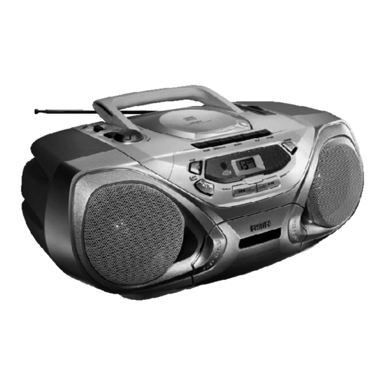
Philips cd stereo radio recorder
Hide thumbs
Also See for AZ1050:
- User manual (21 pages) ,
- User manual (12 pages) ,
- Specifications (2 pages)
Table of Contents
Advertisement
CD Stereo Radio Recorder
TABLE OF CONTENTS
Handling chip components and safety
Technical Specification & Service Tools
..................................................
Service Measurement
................................................
Connections & Controls
.................................................
Instructions for use
...................................................
Disassembly Diagram
........................................
CD Service Test Program
.............................................................
Block Diagram
...........................................................
Wiring Diagram
TUNER BOARD
.......................................................
circuit diagram
.......................................................
layout diagram
COMBI BOARD
...............................................
circuit diagram
....................................................
layout diagram
Safety regulations require that the set be restored to its original
condition and that parts which are identical with those specified
be used.
C
Copyright 1995 Philips Consumer Electroncis B.V. Eindhoven, The Netherlands
All rights reserved. No part of this publication may be reproduced, stored in a retrieval
system or transmitted, in any form or by any means, electronic, mechanical, photocopying,
or otherwise without the prior permission of Philips.
Published by SS 0105 Service Audio
PCS 107 205
chapter
.............................
1 - 1
..........................
2 - 1
2 - 2
3 - 1
3 - 2 to 3 - 5
4 - 1
4 - 2 to 4 - 3
5 - 1
5 - 2
6 - 1
6 - 2
7 - 1, 7 - 3, 7 - 5
7 - 2, 7 - 6
Printed in The Netherlands
FRONT BOARD
.......................................................
circuit diagram
.......................................................
layout diagram
EXPLODED VIEWS DIAGRAM
.................................................................
cabinet
............................................................
tape deck
.....................................................
Mechanical partslist
...............................................
Electrical partslist
Copyright reserved
Subject to modification
AZ1050
AZ1055
all versions
chapter
7 - 4
7 - 4
8 - 1
8 - 2
8 - 2
9 - 1 to 9 - 4
CLASS 1
LASER PRODUCT
3140 785 22620
GB
Advertisement
Table of Contents

Related Manuals for Philips AZ1050


Summary of Contents for Philips AZ1050
- Page 1 LASER PRODUCT Copyright 1995 Philips Consumer Electroncis B.V. Eindhoven, The Netherlands All rights reserved. No part of this publication may be reproduced, stored in a retrieval system or transmitted, in any form or by any means, electronic, mechanical, photocopying, or otherwise without the prior permission of Philips.
-
Page 2: Handling Chip Components
HANDLING CHIP COMPONENTS © ñ WARNING WAARSCHUWING All ICs and many other semiconductors are susceptible to Alle IC´s en vele andere halfgeleiders zijn gevoelig voor electrostatic discharges (ESD). Careless handling during electrostatische ontladingen (ESD). repair can reduce life drastically. Onzorgvuldig behandelen tijdens reparatie kan de levensduur When repairing, make sure that you are connected with the drastisch doen vermindern. -
Page 3: Technical Specifications
TECHNICAL SPECIFICATIONS TUNER - AM SECTION GENERAL Tuning range MW : 522 - 1607 kHz Mains voltage -/00/05/10/14 : 230 V -/17 : 520 - 1730 kHz -/01/11 : 120 / 230 V IF frequency : 468 kHz ± 3 kHz -/17 : 120 V Sensitivity MW : 1500 µV/m at 26dB S/N... -
Page 5: Connections And Controls
CONNECTIONS AND CONTROLS PCS 107 207... - Page 6 INSTRUCTIONS FOR USE PCS 104 276...
- Page 7 INSTRUCTIONS FOR USE PCS 104 277...
- Page 8 INSTRUCTIONS FOR USE PCS 104 278...
- Page 9 INSTRUCTIONS FOR USE PCS 104 279...
-
Page 10: Disassembly Diagram
DISASSEMBLY DIAGRAM A. To remove Handle B. To remove Top Panel C. To remove Front Cabinet Assy D. To remove Tape Deck E. To remove Front Panel F. To remove Tuner Board PCS 104 241... -
Page 11: Service Test Program
SERVICE TESTPROGRAM To enter Service To leave Service Testprogram switch Testprogram hold CD mode off. PLAY & STOP buttons Door switch is ignored Æ depressed while switching CD door can be opened. CD mode on. Display shows Slide servo, Radial servo, Focus servo, Disc motor version number and Laser are switched off. -
Page 12: Cd Startup Procedure
CD STARTUP PROCEDURE Abbreviations and Pin-descriptions of CD ICs SERVO PROCESSOR M62475FP Name Direction Description Diode array Æ CD switched on Remark: To check focus servo, slide servo, track servo and turntable A, B, C Servo processor Current input (central photo diode signal input) BEGIN Diode array Æ... -
Page 13: Block Diagram
BLOCK DIAGRAM 1820 1900 FRONT BOARD REPEAT SHUFFLE TUNER BOARD +B (CD) Stab Stab AM/FM PROGRAM switch FM-IF 1 FM-IF 2 7102 FM-RF Discr. TELESCOPIC RC5' ANTENNA LF filter 10,7 MHz 10,7 MHz 1814 1101 COMBI BOARD left left Stereo right 1812 1201... -
Page 14: Wiring Diagram
WIRING DIAGRAM CD-DRIVE CD 97 DA11 top view DOOR SWITCH BATTERY COMPARTMENT 6 x 1.5V (R20) 8004 +Batt. TELESCOPIC 8800 ANTENNA 8012 8011 HEADPHONE 1810 +Batt. TRANSFORMER 8003 1302 FFC-15 TUNER BOARD 8102 1811 8011 component side view MAINS-SOCKET 1203 1201 to 1202 1900... -
Page 15: Tuner Board - Circuit Diagram
TUNER BOARD - CIRCUIT DIAGRAM 1101 B14 2101 B 4 AM-IF1 468kHz AM-IF2 468kHz 2102 B 4 5106 5108 TUNER BOARD 2103 F 5 REF_A 2104 F 6 2105 H 5 2106 F 5 2118 2106 H 5 REF_A 2106 I 6 2106 I11 2116 2108 I 7... -
Page 16: Tuner Board - Layout Diagram
TUNER BOARD - LAYOUT DIAGRAM TUNER ADJUSTMENT TABLE 1101 A 4 2106 A 3 2113 B 2 2119 B 4 3101 B 4 3109 A 4 5104 B 2 5108 A 1 9101 B 2 2101 A 1 2108 B 3 2114 B 1 2120 B 1 3102 A 4... - Page 17 COMBI BOARD - CIRCUIT DIAGRAM RECORDER / AMPLIFIER PART 1201 I 2 7625 F 5 1202 I14 7625 B 5 COMBI BOARD 1203 K14 7626 D 7 1204 K14 T250 I13 1250 G10 T251 J13 3638 SOURCE 1250 B10 T252 K13 RECORDER/AMPLIFIER PART 2630 2638...
-
Page 18: Combi Board (Az1050) - Layout Diagram
COMBI BOARD (AZ1050) - LAYOUT DIAGRAM 1201 B 1 2806 C 4 2905 D 4 3816 D 3 3901 E 3 9327 E 6 1202 C 6 2807 C 4 2906 E 3 3817 D 4 3902 D 4 9629 B 5... -
Page 19: Front Board
COMBI BOARD (AZ1050) - CIRCUIT DIAGRAM CD PART 1800 E 4 1808 E14 1820 B 2 2806 H19 2812 C24 2818 M 8 2824 P13 2830 M13 2838 D17 2849 L14 2855 F24 2861 L 2 2876 D13 2895 D27... -
Page 20: Front Board - Circuit Diagram
3902 D2 7900 D1 7902 A1 T405 B3 T410 C4 T415 D4 7902 THD3497 PROGRAM SHUFFLE REPEAT FOR AZ1055 FOR AZ1050 1 2 3 4 5 6 7 8 9 1813 T401 T402 T403 T404 T405 T406 T407 T408 T409... - Page 21 COMBI BOARD (AZ1055) - CIRCUIT DIAGRAM CD PART 1807 H15 1901 B10 2805 K19 2811 F24 2817 P 8 2823 M 9 2829 P14 2835 H13 2843 Q 8 2851 F27 2857 N15 2866 G19 2876 G14 2893 Q23 3803 G24 3809 G23 3817 E23 3823 P 9...
- Page 22 COMBI BOARD (AZ1055) - LAYOUT DIAGRAM 1201 B 1 2800 D 3 2891 E 3 3812 B 2 3885 D 1 9325 E 6 1202 C 5 2801 D 1 2892 D 4 3814 C 1 3886 D 2 9326 E 5 1203 C 5 2802 D 4 2893 E 3...
-
Page 23: Exploded View Diagram - Cabinet
EXPLODED VIEW DIAGRAM - CABINET SCREW LIST 1. M2 x 5.5 2. M2.5 x 6 3.Torx 2 x 8 4.Torx 3 x 10 5. Torx 3 x 12 6. Torx 3 x 25 7. Torx 3 x 30 8. T P/W 3 x 16 408c 9. -
Page 24: Mechanical Partslist - Cabinet
MECHANICAL PARTSLIST - CABINET EXPLODED VIEW DIAGRAM - TAPE DECK 401 3140 117 60730 Cass Door Assy (For AZ1050) 432 3140 114 36800 Wheel Tuning 401 3140 117 60800 Cass Door Assy (For AZ1055) 433 3140 114 29800 Pointer 402 4822 492 42709 Cass Door Spring... - Page 25 ELECTRICAL PARTSLIST - COMBI BOARD ELECTRICAL PARTSLIST - COMBI BOARD - CAPACITIORS - - CAPACITIORS - - CAPACITIORS - - RESISTORS - 2101 4822 122 33195 100pF 10% 50V 2628 4822 126 13507 91pF 5% 50V 2827 4822 124 40433 47µF 20% 25V 3101 4822 100 20167 VR 50K 30% 0,1W 2102...
-
Page 26: Electrical Partslist - Combi Board
ELECTRICAL PARTSLIST - COMBI BOARD - RESISTORS - - RESISTORS - 3645 4822 050 11002 1K 1% 0,4W 3847 4822 116 52257 22K 5% 0,5W 3650 4822 116 52213 180R 5% 0,5W 3848 4822 116 52257 22K 5% 0,5W 3651 4822 116 52272 330K 5% 0,5W 3849... - Page 27 0,4W 7601 4822 130 44503 Trans BC547C 3910 4822 050 11503 15K 1% 0,4W 7625 9322 140 00668 IC AN7323S (For AZ1050) 3912 4822 050 12203 22K 1% 0,4W 7625 4822 209 32918 IC AN7318S (For AZ1055) 3913 4822 050 11503 15K 1%...
-
Page 28: Electrical Partslist - Front Board
ELECTRICAL PARTSLIST - FRONT BOARD - CAPACITIORS - 2901 4822 122 33519 470pF 10% 50V 2902 4822 122 33519 470pF 10% 50V 2903 4822 124 23432 100µF 20% 10V 2904 4822 122 33519 470pF 10% 50V 2905 4822 122 33519 470pF 10% 50V - RESISTORS - 3872 4822 116 83882 39K...