
Related Manuals for HUSABERG FE 450 EU


Summary of Contents for HUSABERG FE 450 EU
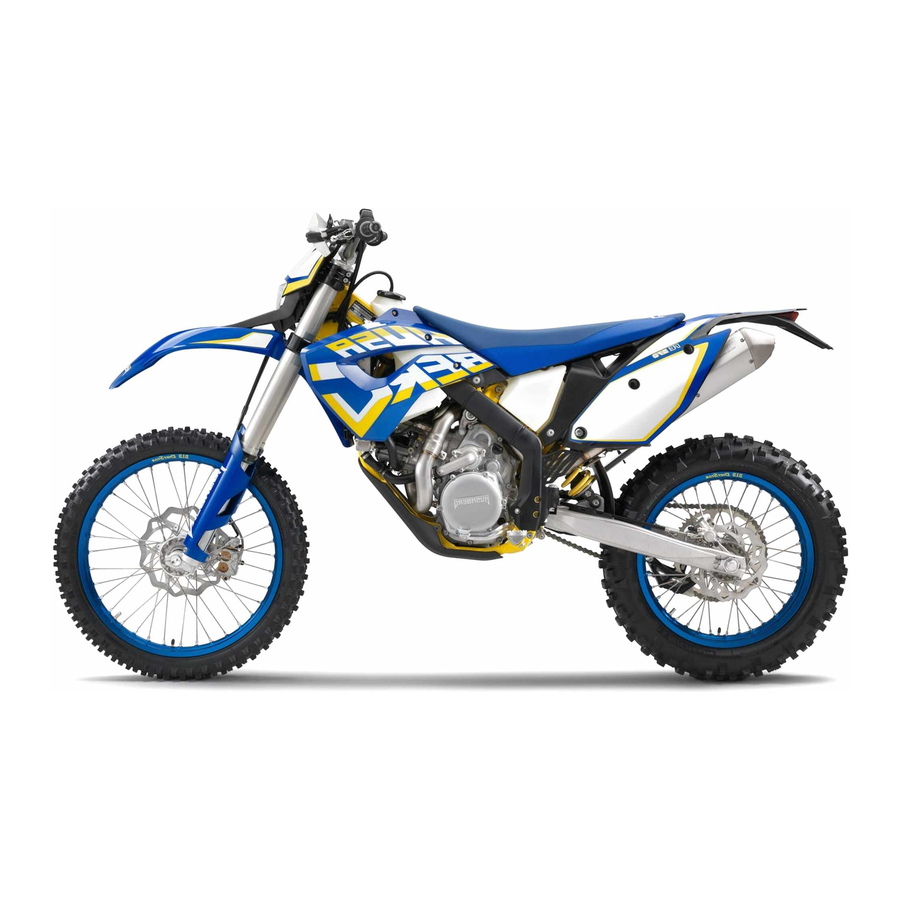
- Page 1 OWNER'S MANUAL FE 450 EU FE 450 AUS FE 501 EU FE 501 AUS FE 501 USA 2014 Art. no. 3802040en...
- Page 3 DEAR HUSABERG CUSTOMER Congratulations on your decision to purchase a HUSABERG motorcycle. You are now the owner of a state-of-the-art sports motorcycle DEAR HUSABERG CUSTOMER that will give you enormous pleasure if you service and maintain it accordingly. We wish you a lot of enjoyment in riding this vehicle.
-
Page 4: Table Of Contents
TABLE OF CONTENTS Setting the service display ....... 22 TABLE OF CONTENTS MEANS OF REPRESENTATION ........5 Speed, time, and DST distance 1 ..... 23 Symbols used ........... 5 Speed, time, and DST2 distance 2 ....23 Formats used............ 5 7.10 AVG average speed, ART operating hours, and SAFETY ADVICE............ - Page 5 TABLE OF CONTENTS 12.10 Installing the fork protector ......44 13.14 Changing the rear brake linings ....70 12.11 Removing the lower triple clamp ....44 14 WHEELS, TIRES ............72 14.1 Removing the front wheel ......72 12.12 Installing the lower triple clamp ....
- Page 6 TABLE OF CONTENTS 23.5 Electrical system........... 103 23.6 Tires ............103 23.7 Fork............. 103 23.8 Shock absorber ..........104 23.9 Chassis tightening torques ......104 24 SUBSTANCES ............106 25 AUXILIARY SUBSTANCES ........108 26 STANDARDS ............110 INDEX ................111...
-
Page 7: Means Of Representation
All work marked with this symbol requires specialist knowledge and technical understanding. In the interest of your own safety, have these jobs performed by an authorized HUSABERG workshop. There, your motorcycle will be optimally cared for by specially trained experts using the specialist tools required. -
Page 8: Safety Advice
Use definition - intended use (FE EU, FE AUS) HUSABERG sport motorcycles are designed and built to withstand the normal stresses and strains of competitive use. The motor- cycles comply with currently valid regulations and categories of the top international motorsport organizations. -
Page 9: Safe Operation
Wear protective clothing (helmet, boots, gloves, pants and jacket with protectors) every time you ride the vehicle. Always wear protective clothing that is in good condition and meets the legal requirements. In the interest of your own safety, HUSABERG recommends that you only operate the vehicle while wearing protective clothing. Work rules Special tools are necessary for certain tasks. -
Page 10: Owner's Manual
Keep the Owner's Manual in an accessible place to enable you to refer to it as needed. If you would like to know more about the vehicle or have questions on the material you read, please contact an authorized HUSABERG dealer. -
Page 11: Important Information
Manufacturer and implied warranty The work prescribed in the service schedule must be carried out by an authorized HUSABERG workshop only and confirmed in the customer's service booklet and in the HUSABERG dealer.net; otherwise, all manufacturer warranty claims shall be void. No manufac- turer warranty claims can be considered for damage resulting from manipulations and/or alterations to the vehicle. -
Page 12: View Of Vehicle
VIEW OF VEHICLE View of vehicle, front left (example) C00519-10 Filler cap Air filter box lid Shift lever ( p. 18) Engine number ( p. 12) Side stand ( p. 18) -
Page 13: View Of Vehicle, Rear Right (Example)
VIEW OF VEHICLE View of vehicle, rear right (example) C00520-10 Fork compression adjustment Kill switch ( p. 14) Horn button ( p. 15) Light switch ( p. 15) Turn signal switch ( p. 15) Emergency OFF switch ( p. 15) Electric starter button ( p. -
Page 14: Serial Numbers
SERIAL NUMBERS Chassis number The chassis number is stamped on the steering head on the right. L00167-10 Type label (FE EU, FE AUS) The type label is fixed to the front of the steering head. L00178-10 Key number (FE EU, FE AUS) The key number for the steering lock is stamped onto the key connector. -
Page 15: Shock Absorber Part Number
SERIAL NUMBERS Shock absorber part number The shock absorber part number is stamped on the top of the shock absorber above the adjusting ring on the engine side. L00169-10... -
Page 16: Controls
CONTROLS Clutch lever The clutch lever is fitted on the left side of the handlebar. The clutch is hydraulically operated and self-adjusting. B01623-10 Hand brake lever Hand brake lever is located on the right side of the handlebar. The hand brake lever is used to activate the front brake. B01624-10 Throttle grip The throttle grip... -
Page 17: Horn Button (Fe Eu, Fe Aus)
CONTROLS Horn button (FE EU, FE AUS) The horn button is fitted on the left side of the handlebar. Possible states • Horn button in neutral position pressed – the horn is actuated in this position. • Horn button L00166-11 Light switch (FE EU, FE AUS) The light switch is fitted on the left side of the handlebar. -
Page 18: Electric Starter Button (Fe Eu, Fe 501 Usa)
CONTROLS 6.11 Electric starter button (FE EU, FE 501 USA) The electric starter button is fitted on the right side of the handlebar. Possible states • Electric starter button in basic position pressed – the electric starter is actuated in this position. •... -
Page 19: Closing Filler Cap
CONTROLS Warning Danger of poisoning Fuel is poisonous and a health hazard. – Fuel must not come into contact with the skin, eyes, or clothing. Do not breathe in the fuel vapors. If contact occurs with the eyes, rinse with water immediately and contact a physician. Immediately clean contaminated areas on the skin with soap and water. -
Page 20: Shift Lever
CONTROLS 6.18 Shift lever Shift lever is mounted on the left side of the engine. B01254-10 The gear positions can be seen in the photograph. The neutral or idle position is between the first and second gears. B01255-10 6.19 Foot brake lever Foot brake lever is located in front of the right footrest. -
Page 21: Steering Lock (Fe Eu, Fe Aus)
CONTROLS 6.21 Steering lock (FE EU, FE AUS) Steering lock is fitted on the left side of the steering head. The steering lock is used to lock the steering. Steering, and therefore riding, is no longer possible. L00188-10 6.22 Locking the steering (FE EU, FE AUS) Note Danger of damage The parked vehicle may roll away or fall over. -
Page 22: Speedometer
Message on the speedometer Possible states Battery voltage of the speedometer – Battery voltage of the speedometer is too low. Change the battery. Service – A service is due. Contact an authorized HUSABERG work- shop. 401901-01 Setting the speedometer Condition The motorcycle is stationary. -
Page 23: Setting Kilometers Or Miles
SPEEDOMETER – Wait for 5 seconds. The speedometer changes to the next menu item. The symbol flashes. Resetting the time – Press the left button. The value decreases. Advancing the time – Press the right button. The value increases. 401912-01 –... -
Page 24: Setting The Clock
SPEEDOMETER Setting the clock Condition The motorcycle is stationary. – Press both buttons for 3–5 seconds. The Setup menu is displayed. The UNIT display flashes. – Wait for the menu of the clock to flash. – Press one of the buttons to select the 24h or 12h display of the clock. 401911-01 –... -
Page 25: Speed, Time, And Dst Distance 1
SPEEDOMETER Speed, time, and DST distance 1 – Press one of the buttons until DST appears on the speedometer. KM/H or M/H shows the speed. shows the time. DST shows the distance since the last reset, such as between two refueling stops. Info If the value of 39999.9 is exceeded, DST is automatically reset to 0.0. -
Page 26: Preparing For Use
When using your motorcycle, remember that others may feel disturbed by excessive noise. – Make sure that the pre-delivery inspection work has been carried out by an authorized HUSABERG workshop. You receive a delivery certificate and the service record at vehicle handover. -
Page 27: Running-In The Engine
For this reason, it may be neces- sary to inspect or replace parts before the next scheduled service. – HUSABERG recommends that you use the specified engine oil for difficult riding conditions and to increase performance. Engine oil (SAE 10W/60) (00062010035) ( p. 106) –... -
Page 28: Preparing For Rides On Dry Sand
– Fit a dust cover on the air filter. Dust protection device for air filter (77206920000) Info See the HUSABERG Pure Tech fitting instructions. 600869-01 – Fit a sand cover on the air filter. Sand protection device for air filter (59006022000) Info See the HUSABERG Pure Tech fitting instructions. -
Page 29: Preparing For Rides On Wet And Muddy Surfaces
Preparing for rides on wet and muddy surfaces – Fit a rain cover on the air filter. Waterproofing device for air filter (77206921000) Info See the HUSABERG Pure Tech fitting instructions. 600870-01 – Fit the steel sprocket. – Clean the motorcycle. ( p. -
Page 30: Riding Instructions
RIDING INSTRUCTIONS Checks and maintenance work when preparing for use Info Before riding the vehicle, always check its condition and operating safety. The vehicle must be in perfect technical condition when used. – Check the engine oil level. ( p. 89) –... -
Page 31: Starting Off
Do not change into a low gear at high engine speed. The engine races and the rear wheel can lock up. Info If you hear unusual noises while riding, stop immediately, switch off the engine and contact an authorized HUSABERG work- shop. -
Page 32: Stopping, Parking
RIDING INSTRUCTIONS Stopping, parking Warning Risk of misappropriation Usage by unauthorized persons. – Never leave the vehicle while the engine is running. Secure the vehicle against use by unauthorized persons. Warning Danger of burns Some vehicle components become very hot when the vehicle is operated. –... -
Page 33: Refueling
– In some countries and regions, the available fuel quality and cleanliness may not be sufficient. This will result in problems with the fuel system. (Your authorized HUSABERG workshop would be pleased to help you.) – Only refuel with clean fuel that meets the specified standards. -
Page 34: Service Schedule
Final check: Check the vehicle for roadworthiness and take a test ride. ○ ● ● Read out the fault memory using the HUSABERG diagnostics tool after a test ride. ○ ● ● Make the service entry in HUSABERG DEALER.NET and in the service record. -
Page 35: Service Work (As Additional Order)
SERVICE SCHEDULE 10.2 Service work (as additional order) Annually Every 135 operating hours/every 70 operating hours when used for motorsports Every 45 operating hours Once after 15 operating hours ● Change the front brake fluid. ● Change the rear brake fluid. ●... -
Page 36: Tuning The Chassis
Caution Danger of accidents Disassembly of pressurized parts can lead to injury. – The shock absorber is filled with high density nitrogen. Adhere to the description provided. (Your authorized HUSABERG workshop would be pleased to help you.) Info The low-speed setting can be seen during the slow to normal compression of the shock absorber. -
Page 37: Adjusting The High-Speed Compression Damping Of The Shock Absorber
Caution Danger of accidents Disassembly of pressurized parts can lead to injury. – The shock absorber is filled with high density nitrogen. Adhere to the description provided. (Your authorized HUSABERG workshop would be pleased to help you.) Info The high-speed setting can be seen during the fast compression of the shock absorber. -
Page 38: Measuring Rear Wheel Sag Unloaded
TUNING THE CHASSIS 11.6 Measuring rear wheel sag unloaded Preparatory work – Raise the motorcycle with a lift stand. ( p. 41) Main work – Measure the distance – as vertically as possible – between the rear axle and a fixed point such as a mark on the side cover. -
Page 39: Adjusting The Spring Preload Of The Shock Absorber
Caution Danger of accidents Disassembly of pressurized parts can lead to injury. – The shock absorber is filled with high density nitrogen. Adhere to the description provided. (Your authorized HUSABERG workshop would be pleased to help you.) Info Before changing the spring preload, make a note of the present setting, e.g., by measuring the length of the spring. -
Page 40: Checking Basic Setting Of Fork
TUNING THE CHASSIS Finishing work – Install the shock absorber. p. 49) – Remove the motorcycle from the lift stand. ( p. 41) – Check the static sag of the shock absorber. ( p. 36) – Check the riding sag of the shock absorber. ( p. -
Page 41: Handlebar Position
TUNING THE CHASSIS – Turn the red adjusting screw all the way clockwise. Info Adjusting screw is located at the upper end of the right fork leg. The rebound damping is located in the right fork leg REB (red adjusting screw). - Page 42 TUNING THE CHASSIS – Position the handlebar clamps. Mount and evenly tighten the four screws Guideline Screw, handlebar clamp 20 Nm (14.8 lbf ft) Info Make sure the gap width is even.
-
Page 43: Service Work On The Chassis
SERVICE WORK ON THE CHASSIS 12.1 Raising the motorcycle with a lift stand Note Danger of damage The parked vehicle may roll away or fall over. – Always place the vehicle on a firm and even surface. – Raise the motorcycle at the frame underneath the engine. Lift stand (81229055100) The wheels must no longer touch the ground. -
Page 44: Loosening The Fork Protector
SERVICE WORK ON THE CHASSIS Warning Danger of accidents Reduced braking efficiency due to oil or grease on the brake discs. – Always keep the brake discs free of oil and grease, and clean them with brake cleaner when necessary. – Clean and oil the dust boots and inner fork tube of both fork legs. -
Page 45: Installing The Fork Legs
SERVICE WORK ON THE CHASSIS – Release screws . Take out the left fork leg. – Release screws . Take out the right fork leg. B01627-10 12.8 Installing the fork legs Main work – Position the fork legs. Info The compression damping is located in the left fork leg COMP (white adjust- ing screw). -
Page 46: Installing The Fork Protector
SERVICE WORK ON THE CHASSIS Main work – Remove screws on the left fork leg. Remove the fork protector upwards. – Remove the screws on the right fork leg. Remove the fork protector upwards. 101327-10 12.10 Installing the fork protector Main work –... -
Page 47: Installing The Lower Triple Clamp
SERVICE WORK ON THE CHASSIS 12.12 Installing the lower triple clamp Main work – Clean the bearing and sealing elements, check for damage, and grease. High viscosity grease ( p. 108) – Insert the lower triple clamp with the steering stem. Mount the upper steering head bearing. -
Page 48: Checking The Steering Head Bearing Play
Danger of accidents Unstable vehicle handling from incorrect steering head bearing play. – Adjust the steering head bearing play without delay. (Your authorized HUSABERG workshop would be pleased to help you.) Info If the bike is ridden with play in the steering head bearing, the bearing and the bearing seats in the frame can become dam- aged over time. -
Page 49: Adjusting The Play Of The Steering Head Bearing
SERVICE WORK ON THE CHASSIS Main work – Move the handlebar to the straight-ahead position. Move the fork legs to and fro in the direction of travel. No play should be noticeable in the steering head bearing. » If there is noticeable play present: –... -
Page 50: Removing The Front Fender
SERVICE WORK ON THE CHASSIS 12.16 Removing the front fender Preparatory work – Switch off all power consumers and switch off the engine. – Remove the headlight mask with the headlight. ( p. 80) Main work – Remove screws – Take the brake line and wiring harness out of the brake line guide. -
Page 51: Installing The Shock Absorber
SERVICE WORK ON THE CHASSIS Main work – Remove screw and lower the rear wheel with the swing arm as far as possible without blocking the rear wheel. Fix the rear wheel in this position. – Remove screw , push splash protector to the side, and remove the shock absorber. -
Page 52: Removing The Air Filter Box Lid
SERVICE WORK ON THE CHASSIS 12.22 Removing the air filter box lid – Release catch , pull off the air filter box lid sideways in areas remove toward the rear. L00241-10 12.23 Installing the air filter box lid – Position the air filter box lid and tab . -
Page 53: Cleaning The Air Filter And Air Filter Box
SERVICE WORK ON THE CHASSIS – Insert both parts together, position them, and fasten them using air filter holder in area The arrow of marking UP faces up. Info If the air filter is not correctly mounted, dust and dirt can enter the engine and cause damage. -
Page 54: Removing The Main Silencer
SERVICE WORK ON THE CHASSIS 12.28 Removing the main silencer Warning Danger of burns The exhaust system gets very hot when the vehicle is driven. – Allow the exhaust system to cool down. Do not touch hot components. Preparatory work – Remove the right side cover. -
Page 55: Removing The Right Side Cover
SERVICE WORK ON THE CHASSIS Main work (FE EU, FE AUS) – Remove screws of connecting cap – Take off the connecting cap with the perforated pipe, O-ring , and glass fiber yarn filling – Remove screws and take off silencer cap with O-ring and stuffing yarn... -
Page 56: Installing The Right Side Cover
SERVICE WORK ON THE CHASSIS 12.32 Installing the right side cover – Position the side cover and engage in area – Mount and tighten screw Guideline Remaining screws, chassis 10 Nm (7.4 lbf ft) L00242-10 12.33 Removing the fuel tank Danger Fire hazard Fuel is highly flammable. -
Page 57: Installing The Fuel Tank
SERVICE WORK ON THE CHASSIS – Remove screw with the rubber bushing. L00197-11 – Pull both spoilers off of the sides of the radiator bracket and lift off the fuel tank. L00200-10 12.34 Installing the fuel tank Danger Fire hazard Fuel is highly flammable. –... -
Page 58: Checking For Chain Dirt Accumulation
SERVICE WORK ON THE CHASSIS – Connect the electrical plug-in connection – Remove the wash cap set. – Thoroughly clean the plug-in connection of the fuel line using compressed air. Info Never let dirt enter the fuel line. Dirt in the fuel line clogs the injection valve. -
Page 59: Checking The Chain Tension
SERVICE WORK ON THE CHASSIS 12.37 Checking the chain tension Warning Danger of accidents Danger caused by incorrect chain tension. – If the chain is too taut, the components of the secondary power transmission (chain, engine sprocket, rear sprocket, bear- ings in the transmission and in the rear wheel) will be under additional load. In addition to premature wear, this can cause the chain or the countershaft of the transmission to break in extreme cases. -
Page 60: Checking The Chain, Rear Sprocket, Engine Sprocket And Chain Guide
SERVICE WORK ON THE CHASSIS Main work – Loosen nut – Loosen nuts – Adjust the chain tension by turning adjusting screws left and right. Guideline Chain tension 55… 58 mm (2.17… 2.28 in) Turn adjusting screws on the left and right so that the markings on the left and right chain adjusters are in the same position relative to the reference marks . - Page 61 SERVICE WORK ON THE CHASSIS – Check the chain sliding guard for wear. » If the bottom edge of the chain bolt is in line with or below the chain sliding guard: – Change the chain sliding guard. – Check that the chain sliding guard is firmly seated. »...
-
Page 62: Checking The Frame
If the swingarm shows signs of damage, cracking, or deformation: – Change the swingarm. Info A damaged swingarm must always be changed. Repair of the swingarm is not authorized by HUSABERG. 401341-01 12.42 Checking the routing of the throttle cable Preparatory work –... -
Page 63: Checking The Rubber Grip
SERVICE WORK ON THE CHASSIS 12.43 Checking the rubber grip – Check the rubber grips on the handlebar for damage, wear, and looseness. » If a rubber grip is damaged, worn, or loose: – Change and secure the rubber grip. Rubber grip adhesive (00062030051) ( p. -
Page 64: Changing The Hydraulic Clutch Fluid
SERVICE WORK ON THE CHASSIS 12.47 Changing the hydraulic clutch fluid Warning Environmental hazard Hazardous substances cause environmental damage. – Oil, grease, filters, fuel, cleaners, brake fluid, etc., should be disposed of as stipulated in applicable regulations. – Move the clutch fluid reservoir mounted on the handlebar to a horizontal position. –... -
Page 65: Brake System
BRAKE SYSTEM 13.1 Checking free travel of hand brake lever Warning Danger of accidents Brake system failure. – If there is no free travel on the hand brake lever, pressure builds up on the front brake circuit. The front brake can fail due to overheating. -
Page 66: Checking The Brake Discs
Warning Danger of accidents Reduced braking efficiency due to old brake fluid. – Change the brake fluid of the front and rear brake according to the service schedule. (Your authorized HUSABERG work- shop would be pleased to help you.) – Move the brake fluid reservoir mounted on the handlebar to a horizontal position. -
Page 67: Checking The Front Brake Linings
Warning Danger of accidents Reduced braking efficiency due to old brake fluid. – Change the brake fluid of the front and rear brake according to the service schedule. (Your authorized HUSABERG work- shop would be pleased to help you.) Warning Environmental hazard Hazardous substances cause environmental damage. -
Page 68: Changing The Front Brake Linings
HUSABERG brake linings. If brake linings are used that differ from the originals, there is no guarantee that they comply with the original license. The vehicle no longer corresponds to the condition at delivery, and the warranty is no longer valid. -
Page 69: Checking The Free Travel Of Foot Brake Lever
BRAKE SYSTEM – Check that leaf spring in the brake caliper and sliding plate in the brake caliper support are seated correctly. 100397-01 – Insert the brake linings, insert the pin, and mount the cotter pin. – Operate the hand brake lever repeatedly until the brake linings are in contact with the brake disc and there is a pressure point. -
Page 70: Checking The Rear Brake Fluid Level
Warning Danger of accidents Reduced braking efficiency due to old brake fluid. – Change the brake fluid of the front and rear brake according to the service schedule. (Your authorized HUSABERG work- shop would be pleased to help you.) – Stand the vehicle upright. -
Page 71: Checking The Rear Brake Linings
Warning Danger of accidents Reduced braking efficiency due to old brake fluid. – Change the brake fluid of the front and rear brake according to the service schedule. (Your authorized HUSABERG work- shop would be pleased to help you.) Warning Environmental hazard Hazardous substances cause environmental damage. -
Page 72: Changing The Rear Brake Linings
HUSABERG brake linings. If brake linings are used that differ from the originals, there is no guarantee that they comply with the original license. The vehicle no longer corresponds to the condition at delivery, and the warranty is no longer valid. - Page 73 BRAKE SYSTEM – Check that leaf spring in the brake caliper and sliding plate in the brake caliper support are seated correctly. L00194-10 – Insert the brake linings, insert the pin, and mount the cotter pin. – Operate the foot brake lever repeatedly until the brake linings are in contact with the brake disc and there is a pressure point.
-
Page 74: Wheels, Tires
WHEELS, TIRES 14.1 Removing the front wheel Preparatory work – Raise the motorcycle with a lift stand. ( p. 41) Main work – Press the brake caliper onto the brake disc by hand in order to push back the brake pistons. -
Page 75: Removing The Rear Wheel
WHEELS, TIRES – Lift the front wheel into the fork, position it, and insert the wheel spindle. – Mount and tighten screw Guideline Screw, front wheel spindle M24x1.5 45 Nm (33.2 lbf ft) – Activate the hand brake lever multiple times until the brake linings are in contact with the brake disc. -
Page 76: Checking The Tire Condition
Checking the tire condition Info Only mount tires approved and/or recommended by HUSABERG. Other tires could have a negative effect on handling characteristics. The type, condition, and air pressure of the tires all have a significant impact on the handling characteristics of the motorcycle. -
Page 77: Checking The Tire Air Pressure
Danger of accidents Instable handling due to incorrect spoke tension. – Ensure that the spoke tension is correct. (Your authorized HUSABERG workshop would be pleased to help you.) Info A loose spoke can cause wheel imbalance, which leads to more loose spokes in a short time. - Page 78 WHEELS, TIRES Guideline Spoke nipple, front wheel M4.5 5… 6 Nm (3.7… 4.4 lbf ft) Spoke nipple, rear wheel M4.5 5… 6 Nm (3.7… 4.4 lbf ft) Torque wrench with various accessories in set (58429094000)
-
Page 79: Electrical System
ELECTRICAL SYSTEM 15.1 Removing the battery Warning Risk of injury Battery acid and battery gases cause serious chemical burns. – Keep batteries out of the reach of children. – Wear suitable protective clothing and goggles. – Avoid contact with battery acid and battery gases. –... -
Page 80: Charging The Battery
– Do not dispose of batteries with the regular garbage. Dispose of defective batteries in an environmentally responsible man- ner. Take the batteries to your HUSABERG dealer or to a collection point for old batteries. Warning Environmental hazard Hazardous substances cause environmental damage. -
Page 81: Changing The Main Fuse
ELECTRICAL SYSTEM 15.4 Changing the main fuse Warning Fire hazard The electrical system can be overloaded if the wrong fuses are used. – Use only fuses with the prescribed amperage. Never by-pass or repair fuses. Info The main fuse protects all power consumers of the vehicle. It is located in the starter relay housing under the air filter box lid. Preparatory work –... -
Page 82: Removing The Headlight Mask With The Headlight
ELECTRICAL SYSTEM – Remove the defective fuse. Guideline Fuse 1 - 10 A - EFI control unit Fuse 2 - 10 A - fuel pump Fuse 3 - 10 A - high beam, low beam, parking light, tail light, license plate lamp Fuse 4 - 10 A - horn, brake light, turn signal, radiator fan Fuses res - 10 A - spare fuses B01642-10... -
Page 83: Changing The Headlight Bulb
ELECTRICAL SYSTEM – Position rubber bands around the fork legs and close them. The wiring harness and brake line are routed in front of the headlight mask. 101855-10 Finishing work – Check the headlight setting. ( p. 82) 15.8 Changing the headlight bulb Note Damage to reflector Reduced brightness. -
Page 84: Checking The Headlight Setting
ELECTRICAL SYSTEM Main work – Remove the screw on the rear of the turn signal housing. – Carefully remove diffuser – Lightly squeeze orange cap in the area of the holding lugs and take it off. – Press the turn signal bulb lightly into the socket, turn it counterclockwise by about 30°, and take it out of the socket. -
Page 85: Changing The Speedometer Battery
ELECTRICAL SYSTEM 15.12 Changing the speedometer battery Preparatory work – Switch off all power consumers and switch off the engine. – Remove the headlight mask with the headlight. ( p. 80) Main work – Remove screws – Pull the speedometer upward out of the holder. B01643-10 –... -
Page 86: Cooling System
COOLING SYSTEM 16.1 Cooling system The water pump in the engine forces the coolant to flow. The pressure resulting from the warming of the cooling system is regulated by a valve in radiator cap . The specified coolant temperature is therefore permissible without the danger of malfunctions. -
Page 87: Checking The Coolant Level
COOLING SYSTEM 16.3 Checking the coolant level Warning Danger of scalding During motorcycle operation, the coolant gets very hot and is under pressure. – Do not remove the radiator cap, radiator hoses or other cooling system components when the engine is hot. Allow the engine and cooling system to cool down. -
Page 88: Refilling Coolant
COOLING SYSTEM 16.5 Refilling coolant Warning Danger of poisoning Coolant is poisonous and a health hazard. – Coolant must not come into contact with the skin, eyes, or clothing. If contact occurs with the eyes, rinse with water imme- diately and contact a physician. Immediately clean contaminated areas on the skin with soap and water. If coolant is swal- lowed, contact a physician immediately. -
Page 89: Tuning The Engine
TUNING THE ENGINE 17.1 Checking the play in the throttle cable – Check the throttle grip for smooth operation. – Move the handlebar to the straight-ahead position. Move the throttle grip back- wards and forwards to ascertain the play in the throttle cable. Play in throttle cable 3…... -
Page 90: Adjusting The Idle Speed
TUNING THE ENGINE 17.3 Adjusting the idle speed – Run the engine warm and push the idle speed adjusting screw all the way in. – Set the desired idle speed by turning the idle speed adjusting screw. Guideline Idle speed 1,950…... -
Page 91: Service Work On The Engine
SERVICE WORK ON THE ENGINE 18.1 Changing the fuel screen Danger Fire hazard Fuel is highly flammable. – Never refuel the vehicle near open flames or burning cigarettes, and always switch off the engine first. Be careful that no fuel is spilt, especially on hot vehicle components. Clean up spilt fuel immediately. –... -
Page 92: Changing The Engine Oil And Oil Filter, Cleaning The Oil Screens
SERVICE WORK ON THE ENGINE 18.3 Changing the engine oil and oil filter, cleaning the oil screens Warning Danger of scalding Engine oil and gear oil get very hot when the motorcycle is ridden. – Wear appropriate protective clothing and safety gloves. In case of burns, rinse immediately with lukewarm water. Warning Environmental hazard Hazardous substances cause environmental damage. - Page 93 SERVICE WORK ON THE ENGINE – Push the engine oil screen with the O-rings onto a pin wrench. – Push the pin wrench through the opening into the drill hole of the opposite engine case wall and push the oil screen as far as possible into the engine case. B01273-10 –...
-
Page 94: Adding Engine Oil
SERVICE WORK ON THE ENGINE – Install and tighten the oil filler plug with O-ring. Danger Danger of poisoning Exhaust gases are toxic and inhaling them may result in unconsciousness and/or death. – When running the engine, always make sure there is sufficient ventila- tion, and do not start or run the engine in an enclosed space without an effective exhaust extraction system. -
Page 95: Cleaning, Care
CLEANING, CARE 19.1 Cleaning the motorcycle Note Material damage Damage and destruction of components by high-pressure cleaning equipment. – When cleaning the vehicle with a pressure cleaner, do not point the water jet directly onto electrical components, connectors, cables, bearings, etc. Maintain a minimum distance of 60 cm between the nozzle of the pressure cleaner and the component. Excessive pressure can cause malfunctions or destroy these parts. -
Page 96: Checks And Maintenance Steps For Winter Operation
CLEANING, CARE 19.2 Checks and maintenance steps for winter operation Info If the motorcycle is used in the winter, salt can be expected on the roads. Precautions need to be taken against road salt corro- sion. If the vehicle was operated in road salt, clean it with cold water after riding. Warm water would enhance the corrosive effects of salt. -
Page 97: Storage
– Store the vehicle in a dry location that is not subject to large fluctuations in tem- perature. Info HUSABERG recommends raising the motorcycle. – Raise the motorcycle with a lift stand. ( p. 41) – Cover the motorcycle with a porous sheet or blanket. Do not use non-porous materi- als since they prevent humidity from escaping, thus causing corrosion. -
Page 98: Troubleshooting
TROUBLESHOOTING Faults Possible cause Action – The engine cannot be cranked (elec- Operating error Carry out the start procedure. ( p. 28) tric starter) – Battery is discharged Charge the battery. p. 78) – Check the charging voltage. – Check the closed current. –... - Page 99 TROUBLESHOOTING Faults Possible cause Action – Engine overheats Foam formation in cooling system Drain the coolant. p. 85) – Refill the coolant. p. 86) – Bent radiator hose Change the radiator hose. – Thermostat defective Check the thermostat. Guideline Opening temperature: 70 °C (158 °F) –...
-
Page 100: Blink Code
BLINK CODE Blink code FI warning lamp (MIL) 02 FI warning lamp (MIL) flashes 2x short Error level condition Crankshaft position sensor - circuit fault Blink code FI warning lamp (MIL) 06 FI warning lamp (MIL) flashes 6x short Error level condition Throttle position sensor circuit A - input signal too low Throttle position sensor circuit A - input signal too high Blink code FI warning lamp (MIL) - Page 101 BLINK CODE Blink code FI warning lamp (MIL) 45 FI warning lamp (MIL) flashes 4x long, 5x short Error level condition FE EU Lambda sensor heater cylinder 1, sensor 1 - short circuit to ground or open circuit Lambda sensor heater cylinder 1, sensor 1 - input signal too high...
-
Page 102: Technical Data
TECHNICAL DATA 23.1 Engine Design 1-cylinder 4-stroke engine, water-cooled Displacement (all 450 models) 449.3 cm³ (27.418 cu in) Displacement (all 501 models) 510.4 cm³ (31.147 cu in) Stroke (all 450 models) 63.4 mm (2.496 in) Stroke (all 501 models) 72 mm (2.83 in) Bore 95 mm (3.74 in) Compression ratio... - Page 103 TECHNICAL DATA ® Nut, water pump impeller 8 Nm (5.9 lbf ft) Loctite 243™ ® Plug, vacuum connection 2.5 Nm (1.84 lbf ft) Loctite 243™ ® Screw plug EVAP 5 Nm (3.7 lbf ft) Loctite 243™ – Screw, alternator cover M6x25 10 Nm (7.4 lbf ft) ®...
-
Page 104: Capacities
TECHNICAL DATA – Screw plug, engine oil screen M20x1.5 15 Nm (11.1 lbf ft) – Screw plug, gear oil screen M20x1.5 15 Nm (11.1 lbf ft) 23.3 Capacities 23.3.1 Engine oil Engine oil 1.50 l (1.59 qt.) Engine oil (SAE 10W/50) ( p. -
Page 105: Electrical System
(FE 501 USA) 80/100 - 21 51M TT 110/100 - 18 64M TT Dunlop GEOMAX MX51 FA Dunlop GEOMAX MX51 Additional information is available in the Service section under: www.husaberg.com 23.7 Fork Fork part number 24.18.7N.69 Fork WP Suspension Up Side Down 4860 4CS... -
Page 106: Shock Absorber
TECHNICAL DATA 23.8 Shock absorber Shock absorber part number 12.45.7M.69 Shock absorber WP Suspension PDS 5018 DCC Compression damping, low-speed Comfort 25 clicks Standard 20 clicks Sport 15 clicks Compression damping, high-speed Comfort 2 turns Standard 1.5 turns Sport 1.25 turns Rebound damping Comfort 28 clicks... - Page 107 TECHNICAL DATA – Screw, engine brace 33 Nm (24.3 lbf ft) – Screw, fork stub 15 Nm (11.1 lbf ft) ® Screw, front brake caliper 25 Nm (18.4 lbf ft) Loctite 243™ – Screw, handlebar clamp 20 Nm (14.8 lbf ft) –...
-
Page 108: Substances
Brake fluid DOT 4 / DOT 5.1 According to – Guideline – Use only brake fluid that complies with the specified standards (see specifications on the container) and that possesses the corre- sponding properties. HUSABERG recommends Castrol and Motorex ® products. Supplier Castrol –... - Page 109 SUBSTANCES Fork oil (SAE 4) (48601166S1) According to – SAE ( p. 110) (SAE 4) Guideline – Use only oils that comply with the specified standards (see specifications on the container) and that possess the corresponding properties. Shock absorber oil (SAE 2.5) (50180342S1) According to –...
-
Page 110: Auxiliary Substances
AUXILIARY SUBSTANCES Air filter cleaning agent Guideline – HUSABERG recommends Motorex ® products. Supplier Motorex ® – Twin Air Dirt Bio Remover Chain cleaner Guideline – HUSABERG recommends Motorex ® products. Supplier Motorex ® – Chain Clean Chain spray Guideline –... - Page 111 – HUSABERG recommends Motorex ® products. Supplier Motorex ® – Twin Air Liquid Bio Power Rubber grip adhesive (00062030051) Supplier KTM-Sportmotorcycle AG / Division HUSABERG – GRIP GLUE Universal oil spray Guideline – HUSABERG recommends Motorex ® products. Supplier Motorex ®...
-
Page 112: Standards
STANDARDS JASO T903 MA Different technical development directions required a new specification for 4-stroke motorcycles – the JASO T903 MA Standard. Ear- lier, engine oils from the automobile industry were used for 4-stroke motorcycles because there was no separate motorcycle specifi- cation. -
Page 113: Index
INDEX Clutch lever ........14 INDEX basic position, adjusting ..... . 61 Accessories . - Page 114 INDEX Fork legs removing ....... . . 44 basic setting, checking ..... . . 38 bleeding .
- Page 115 INDEX Shift lever ........18 Turn signal switch ......15 basic position, adjusting .
- Page 116 INDEX...
- Page 117 KTM-Sportmotorcycle AG / Division HUSABERG Stallhofnerstraße 3 5230 Mattighofen, Austria www.husaberg.com *3802040en* 3802040en...
Need help?
Do you have a question about the FE 450 EU and is the answer not in the manual?
Questions and answers