Table of Contents
Advertisement
Quick Links
FILE No. 810-200601GR
SERVICE MANUAL
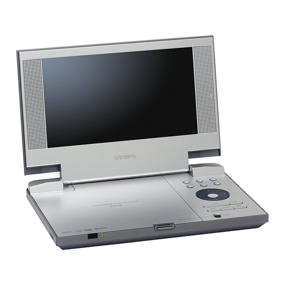
PORTABLE DVD PLAYER
SD-P1850SN
The above model is classified as a green products (*1), as indicated by the underlined serial numbers.
This Service Manual describes replacement parts for green products . When repairing any green
products, use the part(s) described in this manual and lead-free solder (*2).
For (*1) and (*2), see the next page.
Jan.,2006 GREEN
DOCUMENT CREATED IN JAPAN, JANUARY, 2006
Advertisement
Table of Contents

Related Manuals for Toshiba SD-P1850SN


Summary of Contents for Toshiba SD-P1850SN
-
Page 1: Portable Dvd Player
FILE No. 810-200601GR SERVICE MANUAL PORTABLE DVD PLAYER SD-P1850SN The above model is classified as a green products (*1), as indicated by the underlined serial numbers. This Service Manual describes replacement parts for green products . When repairing any green products, use the part(s) described in this manual and lead-free solder (*2). -
Page 2: Green Product Procurement
Hazardous Substances. From July 1, 2006, the RoHS Directive will prohibit any marketing of new products containing the restricted substances. Increasing attention is given to issues related to the global environmental. Toshiba Corporation recognizes environmental protection as a key management tasks, and is doing its utmost to enhance and improve the quality and scope of its environmental activities. -
Page 3: Preparation Of Servicing
LASER BEAM CAUTION LABEL When the power supply is being turned on, you may not remove this laser cautions label. If it removes, radiation of laser may be received. PREPARATION OF SERVICING Pickup Head consists of a laser diode that is very susceptible to external static electricity. Although it operates properly after replacement, if it was subject to electrostatic discharge during replacement, its life might be shortened. -
Page 4: Safty Precautions
SAFTY NOTICE SAFTY PRECAUTIONS LEAKAGE CURRENT CHECK Plug the AC line cord directly into a 120V AC outlet (do Measure the AC voltage across the 1500 resistor. not use an isolation transformer for this check). Use an The test must be conducted with the AC switch on and AC voltmeter, having 5000 per volt or more sensitivity. -
Page 5: Inverter Pcb
DVDVCC BATT+ BATTERY XS102 CD/DVD SW BRIGHT TFT on/off CDMD DVDMD TFT+17V SPR+ CDLD SPR- 3.3V SPL+ TFT GND DVDLD SPL- TFT-13V AVCC TFT+17V STV1 FCS- TRK+ TFT-13V TRK- FCS+ STV2 VCOMS TFT GND VCOMS STH2 TFT5V LIMIT TFT3.3V CPH1 CPH1 LCD G CPH1... -
Page 6: Overall Block Diagram
OVERALL BLOCK DIAGRAM OSCILLATOR DC 9V 16M FlashROM 64M SDRAM OZ9930 74HC4053 27MHz 74HCU04 27MHz MX29LV160ABTC-70 HY57V641620ETP-H 27MHz CARD UPD5500A HIGH VOLTAGE ASS'Y TFT MONITOR RF AMP & SERVO & DVD PROCESSOR VIDEO IN MPEG-2 DECODER & VIDEO ENCODER 74HC4053 ZR36882 DV23 PU mechanism... -
Page 7: Troubleshooting
1. Troubleshooting 1. No power when turned on. 2. The initial screen is not displayed on the LCD. 3. The DVD drive does not work. 4. The operation of the DVD player stops at initializing display. 5. Image output stops during the operation. 6. - Page 8 1.2 The initial screen is not displayed on the LCD. If the initial screen is not displayed on the LCD, check the following items. (1) Check the LED on the front If the LED does not light, proceed to 1.1. (2) Check the backlight If the backlight does not light up, separate the DVD player into top assembly and bottom assembly, and check the Harness, and check the connectors for...
- Page 9 1.3 The DVD drive does not work. When the DVD drive does not work after the power is turned on, check the following items and repair or replace the defective parts. (1) Press the DISC cover switch and turn on the power. Then check whether or not the optical pick-up lens of the DVD drive lights.
- Page 10 1.5 Picture output stops during the operation. If the image output from the media in the DVD player stops during the operation, replace the DVD drive. 1.6 No sound or abnormal sound comes out from the speakers in the DVD player. If no sound comes out from the speakers in the DVD player, check the following: (1) Check for moving images on the LCD screen Check whether or not the picture stops in halfway.
-
Page 11: Main Board Circuit Diagram
MAIN BOARD CIRCUIT DIAGRAM (AUDIO CIRCUIT DIAGRAM) N406 WM8728 VD24 VD25 +P5V STZ6.2N STZ6.2N ALRCLK LRCIN LATI2S FPCSTB(ML) 601H AOUT0# I2CCLK(MC) SCKDSD R282 4K7 ABCLK I2CDAT(MD) BCKIN SDIDEM R304 601H HSJ1594-010060 AMCLK MCLK MUTEB L OUT ZEROR +P5V ZERO MODE R OUT DGND CSBIWL... - Page 12 MAIN BOARD CIRCUIT DIAGRAM (CARD CIRCUIT DIAGRAM) VD22 ESDA5V3SC6 ESDA5V3SC6 DSPVCC33 DSPVCC33 JS508 MEMDA[15:0] R323 R322 SD_ C D MEMDA4 MEMDA4-R SD-CD1 MEMDA3 MEMDA3-R SD-WP1 C314 CB100 MEMDA5 MEMDA5-R XD18-VCC CARD_SEL MEMDA7-R MEMDA2-R XD17-DAT7 10uF/16V MEMDA2 MEMDA6-R 0.1uF DAT0 300Rx 4 XD16-DAT6 MEMDA5-R XD15-DAT5...
- Page 13 MAIN BOARD CIRCUIT DIAGRAM (DVD POWER & CHARGE CIRCUIT DIAGRAM) +P5V R222 BATTERY R223 CB23 R219 100N R221 DV33 POWERSW C196 R220 100N N11A AZ358 L005 C162 C129 C024 C003 C136 R004 CDRH6D38-330MC 10U/16V 100N 10U/16V 100N 100N 100U/16V 16v/100u 10U/16V 100n CATION: REPLACE PUSE WITH SAME...
- Page 14 MAIN BOARD CIRCUIT DIAGRAM (FLASH & DAC & KEY CIRCUIT DIAGRAM) MEMAD[ 1 9:0] MEMAD15 MEMAD14 MEMAD13 MEMAD12 MEMAD11 MEMAD10 XS405 MEMDA[15:0] MEMAD9 FPL0.5B-SMT-45 MEMAD8 MEMAD16 MEMAD18 MEMAD17 MEMAD7 MEMAD6 MEMWR- MEMAD5 MEMAD4 MEMAD3 MEMAD15 MEMAD2 MEMAD14 MEMAD1 BYTE# VCCQ FLASH VCC MEMAD13 MEMAD12...
- Page 15 MAIN BOARD CIRCUIT DIAGRAM (OPU CONNECTOR & DRIVER CIRCUIT DIAGRAM) DVD 5V C272 C138 C273 C140 BGH2012B601LT 10u/16V 100P RF3V3 DVD 3V3 RF3V3 BGH2012B601LT RFA5V R295 BGH2012B601LT C212 47U/16V C269 VD58 R293 220R DVD_LD 10uF/16V BGH2012B601LT KTA1298 C267 C266 C265 C268 C300 100P...
- Page 16 MAIN BOARD CIRCUIT DIAGRAM (TFT DISPLAY CIRCUIT DIAGRAM) R232 601H VDD25 R270 C243 C244 R233 AVDD33 VDD33 VDD25 VD35 VD30 680P 330P 601H RB060L RB060L DV33 TFT-13V C252 C221 +17V# 470N 0.1uF 601H VIDEO-IN 601H C104 R241 AC0/ACB0 390P 470N C199 0.1uF AC1/ACB1...
- Page 17 MAIN BOARD CIRCUIT DIAGRAM (ZA36882 & SDRAM & FLASH CIRCUIT DIAGRAM) VDDPWM DVD3.3V TRACK_S R251 TRACK_S DVD1.8V SLED_S R301 C126 SLED_S SPINDLE_S R249 SPINDLE_PWM SPINDLE_S FOCUS_S R257 FOCUS_PWM C115 FOCUS_S 601H 601H C208 C172 C159 C277 R310 601H 27nF 100K CB20 CB22 CB19...
- Page 18 SD-P1850 TH CIRCUIT DIAGRAM (INVERTER) BAV99 1.5A TFT ON/OFF BRIGHT CON 10U/16V 10U/16V 10U/16V 10U/16V BRIGHT 18P/3KV TFT ON/OFF 820K BHS-2P 470N SST-CMP ISEN VSEN DVD3V3 GDNA VDDA BAV99 330P 2SB709 TFT+13V DRV2 DRV1 10U/16V TFT-13V TFT5V 100K DTC144 RK7002 100N 10U/16V 100N...
- Page 19 MAIN BOARD PCB DIAGRAM (TOP)
- Page 20 MAIN BOARD PCB DIAGRAM (BOTTOM)
- Page 21 SD-KP19(SD-P1850) TH BOARD DIAGRAM (INVERTER)
- Page 22 SD-P1850 CHASSIS ASSEMBLY...
- Page 23 SD-P1850 PACKING ASSEMBLY 1...
- Page 24 SD-P1850 PACKING ASSEMBLY 2 i d e...
-
Page 25: Safety Precaution
PARTS LIST: SD-P1850SN Location Safety TSB P/N Reference No. Description AH301688 e26002 top cover ass'y AH301671 e26003 inverter cover ass'y P000452740 bea7187l LCD unit, LTA080B821A AH301689 e26005 LCD mask AH301486 eb40052 open close locker AH301475 eb40074 LCD mask pad AH301674... - Page 26 1-1, SHIBAURA 1-CHOME, MINATO-KU,TOKYO 105-8001,JAPAN...