Table of Contents
Advertisement
Advertisement
Table of Contents

Related Manuals for JVC RX-D401S


Summary of Contents for JVC RX-D401S
- Page 1 AUDIO / VIDEO CONTROL RECEIVER RX-D401S / RX-D402B INSTRUCTIONS For Customer Use: Enter below the Model No. and Serial No. which are located either on the rear, bottom or side of the cabinet. Retain this information for future reference. Model No.
- Page 2 This Class B digital apparatus complies with Canadian STANDBY/ON, ICES-003. Cet appareil numérique de la classe B est conforme à la norme NMB-003 du Canada. cause harmful interference RX-D401S/RX-D402B JVC Americas Corp. 1700 Valley Road, Wayne New Jersey 07470 973-317-5000 radio...
- Page 3 Introduction We would like to thank you for purchasing one of our JVC products. Before operating this unit, read this manual carefully and thoroughly to obtain the best possible performance from your unit, and retain this manual for future reference.
-
Page 4: Table Of Contents
Introducing the DSP modes ... 35 Using the Surround/DSP modes ... 36 Activating the Surround/DSP modes ... 37 AV COMPU LINK remote control system ... 38 Operating other JVC products ... 40 Operating other manufacturers’ products ... 42 Troubleshooting ... 45 Specifications ... 47 —Quick Speaker Setup ... -
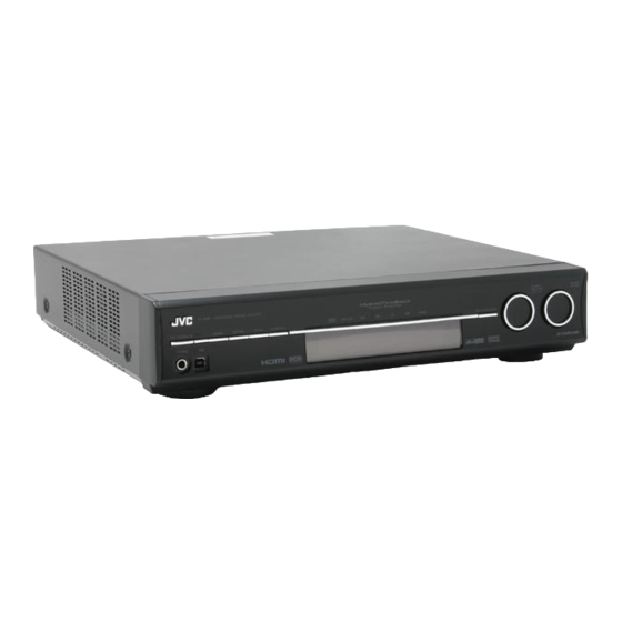
Page 5: Parts Identification
SLEEP button (19) k MIDNIGHT button (25) l TEST button (28) * These buttons can be used for operating a JVC DVD recorder or DVD player with the mode selector set to “DVR” or “DVD” (see page 41). If these buttons do not function normally, use the remote control supplied with your DVD recorder or DVD player. - Page 6 See pages in parentheses for details. Front panel A U D I O / V I D E O C O N T R O L R E C E I V E R STANDBY/ON DIMMER SETTING ADJUST SURROUND PHONES STANDBY/ON button and standby lamp (16) 2 DIMMER button (18) 3 SETTING button (20, 22)
- Page 7 Rear panel VCR(DBS) IN DVR/DVD IN HDMI COMPONENT VIDEO VIDEO VIDEO S-VIDEO DVR/DVD MONITOR VCR(DBS) OUT(REC) IN(PLAY) OUT(REC) IN(PLAY) 1 Power cord (14) 2 HDMI terminals (9) VCR (DBS) IN, DVR/DVD IN, MONITOR OUT 3 AV COMPU LINK-III terminals (38) 4 DIGITAL IN terminals (14) •...
-
Page 8: Getting Started
Getting started Before Installation General precautions • Be sure your hands are dry. • Turn the power off to all components. • Read the manuals supplied with the components you are going to connect. Locations • Install the receiver in a location that is level and protected from moisture and dust. -
Page 9: Connecting The Fm And Am Antennas
Connecting the FM and AM antennas Do not connect the AC power plug to the wall outlet until all connections are completed. AM loop antenna (supplied) Snap the tabs on the loop into the slots of the base to assemble the AM loop antenna. -
Page 10: Connecting The Speakers
Connecting the speakers Do not connect the AC power plug to the wall outlet until all connections are completed. Speaker Layout Diagram (*SB) CAUTIONS: • Use speakers with the SPEAKER IMPEDANCE indicated by the speaker terminals (6 Ω – 16 Ω). •... -
Page 11: Connecting Video Components
Connecting video components Do not connect the AC power plug to the wall outlet until all connections are completed. HDMI connection IMPORTANT: The HDMI video signals from the HDMI terminal are transmitted only through the HDMI MONITOR OUT terminal. Therefore, if the TV is connected to the receiver through the VIDEO jack (MONITOR OUT), S-VIDEO jack (MONITOR OUT), or COMPONENT VIDEO jacks (MONITOR OUT) and a playing video component is connected to the receiver through the HDMI terminal (VCR (DBS) IN or DVR/DVD IN), you cannot view the playback picture on the TV. - Page 12 Audio/video connection In addition to the HDMI terminal, this receiver is equipped with three video terminals—composite video, S-video, and component video terminals, and two audio jacks—analog discrete 5.1 channel audio input jacks (DVD MULTI IN), and stereo audio jacks. • If your video components have S-video (Y/C-separation) and/or component video (Y, P ) jacks, connect them using an S- video cable (not supplied) or component video cable (not...
- Page 13 Do not connect the AC power plug to the wall outlet until all connections are completed. 7 Connecting a DVD recorder or DVD player with its analog discrete output jacks (DVD MULTI IN): If your DVD recorder or DVD player has analog 5.1 channel output jacks, use the connection below. When a DVD Audio disc is played back, the original high-quality sounds can be reproduced by using this connection.
- Page 14 Do not connect the AC power plug to the wall outlet until all connections are completed. 7 Connecting a VCR Turn off all components before making connections. • When you connect other components, refer also to their manuals. COMPONENT VIDEO VCR(DBS) DVR/DVD MONITOR...
- Page 15 Do not connect the AC power plug to the wall outlet until all connections are completed. Turn off all components before making connections. • When you connect other components, refer also to their manuals. 7 Connecting a DBS tuner Green COMPONENT VIDEO Blue VCR(DBS)
-
Page 16: Connecting The Power Cord
Digital audio connection This receiver is equipped with three DIGITAL IN terminals—one digital coaxial terminal and two digital optical terminals—and one DIGITAL OUT terminal. To reproduce the digital sound, use the digital audio connection in addition to the analog audio connection methods described on pages 10 to 13. -
Page 17: Usb Connection
USB connection This receiver is equipped with a USB terminal on the front panel. You can connect your PC to this terminal and enjoy sound reproduced through your PC. When you connect your PC for the first time, follow the procedure below. -
Page 18: Basic Operations
Basic operations Source lamps Turn on the power Press STANDBY/ON (or AUDIO on the remote control). The standby lamp goes off and the source lamp of the current source lights in red. Current source name appears. ANALOG AUTO SURR TUNED STEREO AUTO MUTING S.WFR To turn off the power (into standby) Press... -
Page 19: Adjust The Volume
Selecting the audio input setting You need to select the proper audio input setting according to the connection method (analog or digital) on pages 9 to 14. • In case of digital audio connection using the terminals on the rear of the receiver, you also need to select the correct digital input terminal. -
Page 20: Selecting The Digital Decode Mode
Selecting the digital decode mode This receiver automatically detects the incoming digital signal format when “HDMI” or “DIGITAL” is selected in “AUDIO INPUT” setting (see page 17). When “HDMI” or “DIGITAL” is selected, the digital decode mode is set to “DGTL (digital) AUTO.” If the following symptoms occur while playing Dolby Digital or DTS software with “DGTL AUTO”... -
Page 21: Turning Off The Power With The Sleep Timer
Turning off the power with the Sleep Timer You can fall asleep while listening to music—Sleep Timer. From the remote control ONLY: Press SLEEP repeatedly. • Each time you press the button, the shut-off time changes in 10 minute intervals. The SLEEP indicator lights up on the display. ANALOG AUTO SURR S.WFR... -
Page 22: Basic Settings
Basic settings To obtain the best possible sound effect from Surround/DSP modes (see pages 33 to 37), you need to set up the speaker and subwoofer information after all the connections are completed. From pages 20 to 26, how to set speakers and other basic items of the receiver are explained. -
Page 23: Basic Setting Items
Speakers (channels) number and the size You can find how each of the speaker size is defined according to the number of connected speakers (speaker channel “ch” number) you select. • Subwoofer is counted as 0.1 channel. The size of connected speakers FL/FR SL/SR 2.0CH... -
Page 24: Operating Procedure
Operating procedure Menu operation buttons On the front panel: From the remote control: (5 / ∞ button) (SET button) (2 / 3 button) Before you start, remember... There is a time limit in doing the following steps. If the setting is canceled before you finish, start from step 1 again. - Page 25 Setting the surround back speaker(s)—S BACK OUT Register the number of the surround back speaker(s). < > SB OUT 1SPK Select when you use 1 surround back speaker. < > SB OUT 2SPK Select when you use 2 surround back speakers.
-
Page 26: Activating The Ex/Es/Pliix Setting-Ex/Es/Pliix
Activating the EX/ES/PLIIx setting— EX/ES/PLIIx Depending on this setting, available Surround modes for digital multi-channel software vary—EX/ES/PLIIx (7.1-channel) reproduction or 5.1-channel reproduction. Select an appropriate setting for your enjoyment. • For details about relation between EX/ES/PLIIx setting and available Surround mode, see page 36. •... -
Page 27: Using The Midnight Mode-Midnight Mode
Setting the crossover frequency—CROSSOVER Small speakers cannot reproduce the bass sounds efficiently. If you use a small speaker in any position, this receiver automatically reallocates the bass sound elements assigned to the small speaker to the large speakers. To use this function properly, set this crossover frequency level according to the size of the small speaker connected. -
Page 28: Setting The Audio Delay Level-Audio Delay
Setting the Audio delay level —AUDIO DELAY Synchronization between audio and video reproduction can be possibly disturbed because video signal decoding is time- consuming compared to the audio signal decoding. On this setting, you can correct synchronization between video and audio signals by delaying the audio signal timing. Adjustable range: OFF and 10 ms to 100 ms (in 10 ms intervals) >... -
Page 29: Sound Adjustments
Sound adjustments You can make sound adjustment to your preference after completing basic setting. Basic adjustment items You can adjust the following items. See pages in parentheses for details. • You cannot select the items which is not available with the current setting. -
Page 30: Adjusting The Speaker Output Levels
Press 2 / 3 button repeatedly to adjust the selected item. • On the front panel, turn MULTI JOG. ANALOG S.WFR –10 Your adjustment is stored. Press SET. Repeat steps 2 to 5 to adjust other items if necessary. Press EXIT. •... -
Page 31: Adjusting The Bass Sounds
Adjusting the bass sounds Reinforcing the bass—BASS BOOST You can boost the bass level—Bass Boost. • Once you have made an adjustment, it is memorized for each source. < > B BOOST Select to boost the bass level. The B.BOOST indicator lights up on the display. - Page 32 Adjusting the panorama control for Pro Logic IIx Music and Pro Logic II Music—PANORAMA This setting is available when Pro Logic IIx Music or Pro Logic II Music is activated for the analog or digital 2-channel sound signal. To activate Pro Logic IIx Music or Pro Logic II Music, see page 37. •...
-
Page 33: Tuner Operations
Tuner operations Tuner operations are mainly done from the remote control. TUNING/REW FF/TUNING FM MODE MEMORY NOTE When you have selected “FM” or “AM” by using SOURCE SELECTOR on the front panel, the remote control may not work for tuner operations. To use the remote control for tuner operations, select “FM”... -
Page 34: Selecting The Fm Reception Mode
Press the numeric buttons (1 – 10, +10) to select a channel number while the channel number position is flashing. • For channel number 5, press 5. • For channel number 15, press +10, then 5. • For channel number 30, press +10, +10, then 10. ANALOG TUNED STEREO AUTO MUTING S.WFR... -
Page 35: Creating Realistic Sound Fields
Creating realistic sound fields Reproducing theater ambience In a movie theater, many speakers are located on the walls to reproduce impressive multi-channel sound, reaching you from all directions. With these many speakers, sound localization and sound movement can be expressed. Surround/DSP modes built in this receiver can create almost the same Surround sound as you can feel in a real movie theater. - Page 36 • If both “SURROUND SPK” and “CENTER SPK” are set to < > “ ” in the speaker setting (see page 22), JVC’s original 3D-PHONIC processing (which has been developed to create the surround effect through the front speakers only) is used. The 3D-PHONIC indicator lights up on the display.
-
Page 37: Introducing The Dsp Modes
When using the DAP mode, the sounds come out of all the connected and activated speakers. • If “SURROUND SPK” is set to “ setting (see page 22), JVC’s original 3D-PHONIC processing (which has been developed to create the surround effect through the front speakers only) is used. -
Page 38: Using The Surround/Dsp Modes
Using the Surround/DSP modes Available Surround/DSP modes vary depending on the speaker settings and the incoming signals. See the table below. • The numbers inside the parentheses following the incoming signal type indicate the number of the front channels and that of the surround channels. -
Page 39: Activating The Surround/Dsp Modes
Activating the Surround/DSP modes Available Surround/DSP modes vary depending on the speaker settings and the incoming signals. For details, see page 36. Activating one of the Surround/DSP modes automatically recalls the memorized settings and adjustments. • To adjust the speaker output level, see page 28. •... -
Page 40: Av Compu Link Remote Control System
This receiver is equipped with the AV COMPU LINK-III, which has added a function to operate JVC’s video components through the component video jacks. To use this remote control system, you need to connect the video components you want to operate, following the diagrams below and the procedures on page 37. - Page 41 Connecting procedure If you have already plugged your VCR, DVD player, TV, and this receiver into the AC outlets, unplug their AC power cords first. Connect your VCR, DVD player, TV, and this receiver as follows, using the cables with the monaural mini-plugs (not supplied).
-
Page 42: Operating Other Jvc Products
“A” and “B.” This remote control can operate a VCR whose remote control code is set to “A.” – Some JVC DVD recorders can accept four types of the control signals. This remote control can operate a DVD recorder whose remote control code is set to the initial code. - Page 43 7 Changing the remote control code for DVD recorder Some JVC DVD recorders can accept four types of the control signals. You can assign one of four codes to the remote control supplied with this receiver for operating your DVD recorder.
-
Page 44: Operating Other Manufacturers' Products
Operating other manufacturers’ products By changing the transmittable signals, you can use the supplied remote control to operate other manufacturers’ products. • Refer also to the manuals supplied with the other products. • To operate those components with the remote control, first you need to set the manufacturers’... - Page 45 ❏ Changing the transmittable signals for operating a VCR Press and hold VCR Press VCR. Enter the manufacturer’s code using buttons 1 – 9, and 0. See “Manufacturers’ codes for VCR” on the right. Release VCR Now, you can perform the following operation on the VCR. Turn on or off the VCR.
- Page 46 ❏ Changing the transmittable signals for operating a CATV converter or DBS tuner Press and hold DBS/CATV Press DBS. Enter the manufacturer’s code using buttons 1 – 9, and 0. See “Manufacturers’ codes for CATV converter” or “Manufacturers’ codes for DBS tuner” below. Release DBS/CATV Now, you can perform the following operation on the CATV converter or DBS tuner.
-
Page 47: Troubleshooting
No picture on the TV screen. HDMI signals do not come on. Use this chart to help you solve daily operational problems. If there are any problems you cannot solve, contact your JVC’s service center. POSSIBLE CAUSE The power cord is not plugged in. - Page 48 Remote control does not operate as you intend. Remote control does not work. Continuous hiss or buzzing during FM reception. Occasional cracking noise during FM reception. The remote control is not ready for your intended operation. There is an obstruction hiding the remote sensor on the receiver.
-
Page 49: Specifications
Specifications Designs and specifications are subject to change without notice. Amplifier Output Power At stereo operation: Front channels: 110 W per channel, min. RMS, driven into 6 Ω at 20 Hz to 20 kHz with no more than 0.8% total harmonic distortion. - Page 52 © 2005 Victor Company of Japan, Limited 0705RYMMDWJEIN...