Table of Contents
Advertisement
62061
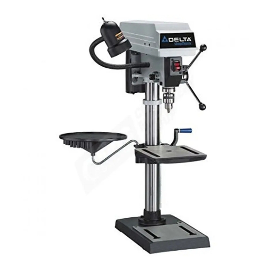
12" Bench Drill Press
(Model DP300)
PART NO. 905575-04-29-04
Copyright © 2004 Delta Machinery
RTD10000126AA
To learn more about DELTA MACHINERY
ESPAÑOL: PÁGINA 17
visit our website at: www.deltamachinery.com.
For Parts, Service, Warranty or other Assistance,
1-800-223-7278 (
1-800-463-3582).
please call
In Canada call
Advertisement
Table of Contents

Related Manuals for Delta DP300


Summary of Contents for Delta DP300
- Page 1 62061 12" Bench Drill Press (Model DP300) PART NO. 905575-04-29-04 Copyright © 2004 Delta Machinery RTD10000126AA To learn more about DELTA MACHINERY ESPAÑOL: PÁGINA 17 visit our website at: www.deltamachinery.com. For Parts, Service, Warranty or other Assistance, 1-800-223-7278 ( 1-800-463-3582).
-
Page 2: Safety Guidelines - Definitions
If you have any questions relative to a particular application, DO NOT use the machine until you have first contacted Delta to determine if it can or should be performed on the product. - Page 3 2. WEAR EYE PROTECTION. ALWAYS USE SAFETY accessories and attachments not recommended by Delta may cause damage to the machine or injury to the GLASSES. Also use face or dust mask if cutting operation is dusty. Everyday eyeglasses are NOT safety user.
- Page 4 ADDITIONAL SAFETY RULES FOR FOR DRILL PRESSES FAILURE TO FOLLOW THESE RULES MAY RESULT IN SERIOUS INJURY. DO NOT OPERATE THIS MACHINE until it is 13. AVOID AWKWARD OPERATIONS AND HAND completely assembled and installed according to POSITIONS. A sudden slip could cause a hand to the instructions.
-
Page 5: Power Connections
POWER CONNECTIONS A separate electrical circuit should be used for your machines. This circuit should not be less than #12 wire and should be protected with a 20 Amp time lag fuse. If an extension cord is used, use only 3-wire extension cords which have 3- prong grounding type plugs and matching receptacle which will accept the machine’s plug. -
Page 6: Extension Cords
FOREWORD The Delta ShopMaster Model DP300 12" Drill Press comes with a flexible work lamp, and a utility tray for keeping tools within easy reach. This machine has a tilting table for angle drilling and side edges and parallel slots for fast workpiece clamping. -
Page 7: Carton Contents
CARTON CONTENTS Drill Press Head and Motor M8x1.25x125mm Carriage Head Screws (2), M8 Flat Washers (2), M8.1 Lock Washers (2), M8x1.25 Table Hex Nuts (2) (for fastening the base to a supporting Column, Base Flange and Rack surface) Base 10. Chuck Key M8x1.25x25mm Hex Head Cap Screws (4) 11. - Page 8 ASSEMBLY For your own safety, do not connect the machine to the power source until the machine is completely assembled and you read and understand the entire instruction manual. Fig. 3 Fig. 4 Attach the column (A) Fig. 3 to the base (B) using the four M8x1.25x25mm hex head screws (C), three of which are shown.
- Page 9 NOTE: Place the bottom of the raising rack (F) Fig. 8 inside the flange (L) on the drill press base. Fig. 8 Fig. 8 Fig. 10 Fig. 9 5. Place the mounting bracket (A) Fig. 9 on the column. NOTE: To avoid interference with the spindle height adjusting handles (P) Fig. 16, place the mounting bracket on the opposite side of the column from the raising rack.
- Page 10 Thread the stud of the clamp handle (M) Fig. 14 in the hole in the rear of the table bracket. Seat the drill press head (N) Fig. 15 on the column. Align the head (A) Fig. 15A, with the table (B) and base (C). Tighten the two head locking screws (O) Fig.
-
Page 11: Operating Controls And Adjustments
FASTENING DRILL PRESS TO SUPPORTING SURFACE If, during operation, the machine has a tendency to tip over, slide, or walk on the supporting surface, secure the machine base to the supporting surface with an M8x1.25x125mm carriage head screw, 8.5mm flat washer, 8.5mm lock washer, M8x1.25 hex nut through the two holes (A) Fig. -
Page 12: Table Adjustments
TABLE ADJUSTMENTS Raise or lower the table on the column by loosening the table clamp (A) Fig. 23, and turning the table raising and lowering handle (B) Fig. 24. After the table is at the desired height, tighten the clamp (A) Fig. 23. NOTE: Always raise (rather than lower) the table to the final position to allow the gears to mesh and prevent Fig. -
Page 13: Spindle Speeds
SPINDLE MOTOR 3100 2340 1720 1100 Fig. 28 Fig. 29 SPINDLE SPEEDS Five spindle speeds (620, 1100, 1720, 2340, and 3100 RPM) are available with your drill press. See the chart in Fig. 28 to select the correct belt placement for your project. CHANGING SPEEDS AND ADJUSTING BELT TENSION NOTE: A belt-positioning speed chart (E) Fig. -
Page 14: Adjusting Spindle Return Spring
Fig. 32 Fig. 31 OPERATION The use of accessories and attachments not recommended by Delta may result in risk of injury. IMPORTANT: When the workpiece (A) Fig. 33 is long enough, position it on the table with one end against the left side of the column (B) to prevent the workpiece from rotating. -
Page 15: Installing And Removing Drill Bits
INSTALLING AND REMOVING DRILL BITS Fig. 34 NOTE: Use drill bits with a shank of 1/2" or less in diameter. DISCONNECT MACHINE FROM POWER SOURCE. Insert the smooth end of drill bit (A) Fig. 34 in the chuck (B) as far as it will go, and then back the bit out 1/16" (or up to the flutes for small bits). -
Page 16: Parts, Service Or Warranty Assistance
Two Year Limited New Product Warranty Delta will repair or replace, at its expense and at its option, any new Delta machine, machine part, or machine accessory which in normal use has proven to be defective in workmanship or material, provided that the customer returns the product prepaid to a Delta factory service center or authorized service station with proof of purchase of the product within two years and provides Delta with reasonable opportunity to verify the alleged defect by inspection. - Page 17 Phone: (514) 336-8772 Fax: (604) 420-3522 Fax: (514) 336-3505 The following are trademarks of PORTER-CABLE • DELTA (Las siguientes son marcas registradas de PORTER-CABLE • DELTA S.A.) (Les marques suivantes sont des marques de fabriquant de la PORTER-CABLE • DELTA): Auto-Set ®...
Need help?
Do you have a question about the DP300 and is the answer not in the manual?
Questions and answers