
Related Manuals for QEP TILE SAW 60707


Summary of Contents for QEP TILE SAW 60707
-
Page 1: Instruction Manual
MASTER CUT PORTABLE TILE SAW INSTRUCTION MANUAL MODEL NO.60707 Carefully read the instruction manual before you use this machine, and save this instruction manual for future reference. - 1 -... -
Page 2: Table Of Contents
TABLE OF CONTENTS PAGE WARNING SYMBOLS ……… GENERAL SAFETY INSTRUCTIONS FOR POWER TOOLS …… SPECIAL SAFETY INSTRUCTIONS FOR TILE CUTTER TECHNICAL SPECIFICATIONS Technical specifications Electrical safety UNPACKING LOOSE PARTS LIST FEATURES ASSEMBLY AND OPERATION 10-11 Assembly of the tile cutter Fitting the Tile Cutter on a Work Bench Cut preparation Rip cutting... -
Page 3: Warning Symbols
WARNING SYMBOLS WARNING! There are six warning symbols on the warning label which is affixed to the tile cutter. The purpose of warning symbols is to attract your attention to possible hazardous conditions. The progression of warning symbols is described below. Remember that safety messages by themselves do not eliminate danger and are not a substitute for proper accident prevention measures. -
Page 4: General Safety Instructions For Power Tools
GENERAL SAFETY INSTRUCTIONS FOR POWER TOOLS IMPORTANT! When using electrical tools, the following safety instructions should be observed to prevent the risk of electric shock, personal injury and fire. Read and observe these instructions carefully before using the Tile Saw. Also use a dust mask during pulverulent 1. -
Page 5: Special Safety Instructions For Tile Cutter
Form the habit of checking to see that parts, binding of moving parts, breakage of keys and adjusting wrenches are removed parts, mounting, and any other conditions from the tool before switching it on. that may affect its operation. A guard or other part that is damaged should be 17. -
Page 6: Technical Specifications
wear, or looseness. Replace any 13. Side grinding damaged or worn parts. ALWAYS Do not use the blade for grinding purposes, DISCONNECT FROM POWER BEFORE e.g. for grinding the edge of a tile after CHANGING OR ADJUSTING THE cutting it. Do not carry out radius or curve BLADE. -
Page 7: Unpacking
supply (±10% AC 230V), the rotational ground. Do not touch plugs with wet hands. speed of the spindle will never exceed the Failure to follow these warning could result rated no-load speed. in serious injuries. 2. This machine must have a ground prong in the plug to help ensure that it is Grounding In the event of an electrical short circuit,... -
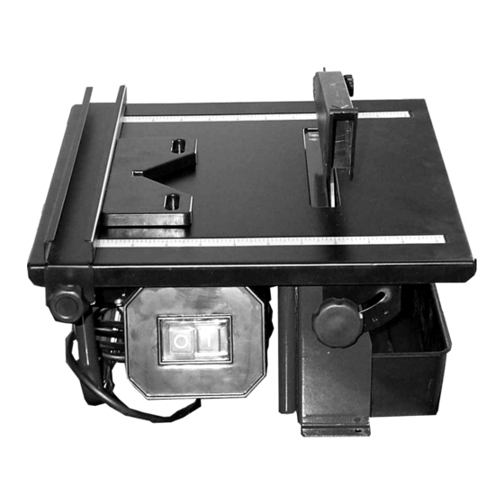
Page 8: Features
Blade guard parallel guide 180mm Continuous rim diamond blade Miter gauge FEATURES Before attempting to use, familiarize yourself with all the operating features and safety requirements of your tile cutter. Blade Blade guard Miter gauge Parallel guide Table Water tank Table tilting mechanism /locking knob Cable and plug... - Page 9 Any use other than its intended use is a case Blade This machine comes with a standard Φ180mm of misuse. The user/operator and not the blade w/bore 22.2mm diamond blade. manufacturer shall be liable for any damage or WARNING! Only use the continuous rim injury resulting from case of misuse.
-
Page 10: Assembly And Operation
ASSEMBLY AND OPERATION Assembly of the tile cutter on the workbench Figure 2 shows the dimensions of mounting holes which have been pre-drilled on the machine frame. 1. Drill three holes in the workbench as the WARNING! Only use the machine after it has same dimensions as Fig. -
Page 11: Bevel Cutting
4. Use spanner A and spanner B to loosen Figure 4: Diagonal cutting with the miter gauge. and remove the arbor nut from the motor spindle as shown in Figure 7. Bevel cutting Outer flange Arbor nut The work table can be tilted up to 45 accommodate bevel cutting. -
Page 12: Exploded View
EXPLODED VIEW - 12 -... -
Page 13: Parts List
PARTS LIST Part Part Description Q’ty Description Q’ty Nut (M5) 26-5 Fixing Plate Blade Guard 26-6 Capacitor Plastic pad 26-7 Rubber Tube 26-8 VDE Cable & Plug Riving Knife Washer Bolt Screw Washer Knob Screw Table Washer Knob Screw Washer Water Tank Clamping Plate Parallel Guide... - Page 14 26-3 Switch 26-4 Terminal Block - 14 -...
Need help?
Do you have a question about the TILE SAW 60707 and is the answer not in the manual?
Questions and answers