Table of Contents
Advertisement
www.ajantunes.com
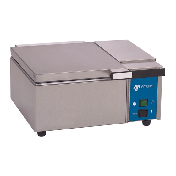
DFW series
deluxe food warmer
owner's manual
Manufacturing Numbers:
9100101, 9100102, 9100103, 9100104,
9100105, 9100106, 9100107, 9100111,
9100112, 9100113, 9100114, 9100115,
9100116, 9100118, 9100121, 9100122,
9100123, 9100124, 9100125, 9100126,
9100128, 9100131, 9100132, 9100133,
9100134, 9100135, 9100136, 9100146,
9100147, 9100156
STOP
PROGR AM START/
DOWN
UP
POW ER
P/N 1010678 Rev. K 08/12
Advertisement
Table of Contents

Related Manuals for Roundup DFW series


Summary of Contents for Roundup DFW series
- Page 1 STOP PROGR AM START/ DOWN POW ER DFW series deluxe food warmer owner’s manual Manufacturing Numbers: 9100101, 9100102, 9100103, 9100104, 9100105, 9100106, 9100107, 9100111, 9100112, 9100113, 9100114, 9100115, 9100116, 9100118, 9100121, 9100122, 9100123, 9100124, 9100125, 9100126, 9100128, 9100131, 9100132, 9100133,...
-
Page 2: Table Of Contents
Your Deluxe Food Warmer (steamer) is manu- Diagnostic LEDs ........8 factured from the finest materials available Daily Maintenance ......... 8 and is assembled to Roundup’s strict quality Date of Purchase Monthly Maintenance ......9 standards. This unit has been tested at the Troubleshooting........ -
Page 3: Important Safety Information
IMPORTANT SAFETY WARNINGS INFORMATION • Do not use a sanitizing solution or Be advised of the following warnings when operating and performing maintenance on abrasive materials. The use of these Use the following guidelines for safe opera- may cause damage to the stainless this unit. -
Page 4: Specifications
50/60 9100124 15 Amp, 120 Volt CAPACITIES DFWT-150 NEMA 5-20P 1800 50/60 9100125 20 Amp. 120 Volt DFW Series 2-7/8” (7.3 cm) Deep Half-size steam table pan DFWT-150 CEE 7/7 2800 12.2 50/60 9100126 16 Amp. 250 Volt DFWT Series 2-7/8”... -
Page 5: Installation
INSTALLATION Connect Quick Disconnect NOTE: When placing the unit, make sure Insert Here Flexible Nylon Braided Cold to provide at least 3 inches of space on Quick 1/4 " I.D. Tubing (Not Supplied) Water Disconnect all sides of the unit. Flow Insert 1. -
Page 6: General Information
GENERAL INFORMATION WARNING ALL MODELS To avoid injury, be careful when opening top cover. Be sure to allow steam to escape When the OPERATE button is pressed, power before putting hands or face over the is supplied to the water pump (Water Tank steamer. -
Page 7: Programming
PROGRAMMING 2. Press and release the PROGRAM 8. Press and release the PROGRAM button to change the control from button again and “H2O” is displayed CYC (Total Cycle Time) refers to the total Operation to Program mode. (Item G, Figure 4). amount of steaming time set for the product. -
Page 8: Hi-Limit Reset Button
DIAGNOSTIC LEDS CAUTION Reset Button TIMER MODELS Do not use a sanitizing solution or abrasive materials. The use of these may cause dam- This control board has 4 diagnostic LEDs age to the stainless steel finish. described below. Green (Program): When lit, indicates the unit CAUTION is in Program mode. -
Page 9: Monthly Maintenance
Top Cover Trivet Assy. Gasket Hinge Pin Diffuser Spray Tube Assy. Steam Generator Surface Figure 6. Deluxe Food Warmer Components (DFW-150 Shown) MONTHLY MAINTENANCE 6. Use a scraper or spatula to remove the Seasoning mixture consists of 3/4 ounces (25 excessive calcium/mineral buildup from ml/25 cc) baking soda, 3/4 ounces (25 ml/25 CLEAN SPRAY TUBE AND STEAM... - Page 10 MONTHLY MAINTENANCE Water Tank Filter Tank Cover WATER TANK FILTER Filter Stem (DFW/DFWT-100/150 ONLY) Bottom Hole of Water The water tank filter is used to prevent par- Tank ticles or food products from entering and Access Cover damaging the water pump. Inspect and clean with Tank (dotted line) this filter monthly or more regularly using the...
-
Page 11: Troubleshooting
TROUBLESHOOTING WARNING To avoid possible personal injury and/or damage to the unit, inspection, test, and repair of electrical equipment should be performed by qualified service personnel. The unit should be unplugged when servicing, except when electrical tests are required. Use extreme care during electrical circuit tests. - Page 12 TROUBLESHOOTING (continued) Problem Possible Cause Corrective Action Unit heats but there is little or no Water Line Valve is closed (DFW/DFWT/DFWF- Check that the Water Line Valve is open. steam produced and/or 200/250). The product requires more steaming Filter Strainer and/or Spray Tube is restricted. Check and clean the Filter Strainer and Spray Tube than usual.
- Page 13 TROUBLESHOOTING (continued) Problem Possible Cause Corrective Action Steam Generator’s surface becomes Insufficient pre-heat time. Remove excess water from the Generator surface flooded (fills with excess water). and allow the unit 30 minutes of pre-heat time. The Green Momementary Switch is pressed for lon- Follow the “one in twenty”...
-
Page 14: Cooking Guide
COOKING GUIDE Use the suggested cooking times below on noodles, rice, cereals, breads, meat, seafood, poultry, eggs, and vegetables, or experiment with your own products and steaming times. A little more or less steam could enhance the appearance and flavor. Product Minutes Product... -
Page 15: Replacement Parts
REPLACEMENT PARTS Dual Water Pressure Regulator Kit - Part No. 7000235 Item Part No. Description Qty. To Steamer 2080105 Elbow, Quick Disconnect - 1/4” To Steamer 2030126 Tubing 1/4” I.D. PVC BRD. 24” Long 2030125 Tubing 1/4” I.D. PVC BRD. 12” Long 2040150 Elbow, Male - Nylon 1/4”... -
Page 16: Replacement Parts - Dfw/Dfwt-100/150
REPLACEMENT PARTS – DFW/DFWT-100/150 Inset A - Parts are used on DFWT-150 with manufacturing number 9100128 only. See Inset A Inset B Inset C (Non-Timer) Models DFW/DFWT-100 See Inset B NE S AN TU IN US MA DE R1 8 See Inset C SE RI R1 1... - Page 17 80 304P105* Nut, Hex, #4-40 KEPS 13 210K230 Leg, 1” (Pack of 4) 81 1000275 Label, Water & Waste 42 7000136 Terminal Block Kit 14 0503069 Base Plate (DFW Series) 1 (Incl. No. 43) Connection 0503178 Base Plate (DFWT Series) 1 43 100P967* Marking Label * Only available in packages of 10.
-
Page 18: Replacement Parts - Dfw/Dfwt-200/250
REPLACEMENT PARTS – DFW/DFWT-200/250 See Page 15 for Strainer Parts Inset B Inset C (Non-Timer) See Inset B Models DFW/DFWT-200 See Inset C Inset C Timer Models DFW/DFWT-250 P/N 1010678 Rev. K 08/12... - Page 19 13 210K230 Leg, 1" (Pack of 4) (Incl. Nos. 46, 47 & 48) 81 1000275 Label, Water & Waste 14 0503069 Base Plate (DFW Series) 1 46 204P114* Elbow, Female, 1/4" Tube 1 Connection 0503178 Base Plate (DFWT Series) 1 47 2000188 Outlet Tube * Only available in packages of 10.
-
Page 20: Replacement Parts - Dfwf-250 Only
REPLACEMENT PARTS – DFWF-250 ONLY Inset A Inset B Non-Timer Model Timer Model Mfg. No. 9100147 only See Page 25 See Inset B for Strainer Parts 9 (See Page 5) Inset A P/N 1010678 Rev. K 08/12... - Page 21 REPLACEMENT PARTS – DFWF-250 ONLY (continued) Item Part No. Description Qty. Item Part No. Description Qty. Item Part No. Description Qty. 0011165 Top Cover Assy. 23 0800219 Top Cover Hinge Pin 2 41 0010584 Inlet House Assy. (Incl. Items 2, 3, & 4) with Strainer 24 0501569 Cover Hinge Base 0020769 Top Cover Shell...
-
Page 22: Wiring Diagram
WIRING DIAGRAM DFW/DFWT/DFWF-150/250 Only Timer Models Only - Except DFWF-250 units with Mfg. No. 9100147 WIRING DIAGRAM POWER CORD NOTE: ALL WIRES TO BE 14 GA. AWM-105°C UNLESS OTHERWISE SPECIFIED. # 18 GA. AWM-105°C 22 GA. AWM-105°C MOMENTARY THERMOCOUPLE SWITCH TERMINAL BLOCK HEATER... - Page 23 WIRING DIAGRAM (continued) DFW/DFWT-100/200 and DFWF-250 Models with Mfg. No. 9100147 Only. Timer Models Only. WIRING DIAGRAM POWER NOTE: ALL WIRES TO BE 14 GA. AWM-105°C CORD UNLESS OTHERWISE SPECIFIED. # 18 GA. AWM-105°C 22 GA. AWM-105°C THERMISTOR S.S. RELAY TERMINAL BLOCK HEATER...
-
Page 24: Limited Warranty
2. Roundup reserves the right to make changes in design or add any improvements on any product. The right is always reserved to modify equipment because of factors beyond our control and government regulations. Changes to update equipment do not con- stitute a warranty charge.
Need help?
Do you have a question about the DFW series and is the answer not in the manual?
Questions and answers