Advertisement
Quick Links
Advertisement

Related Manuals for Renishaw H-2000-5015-05-N


Summary of Contents for Renishaw H-2000-5015-05-N
- Page 1 Installation and user’s guide H-2000-5015-05-N MI 8 interface unit...
- Page 2 © 1995 Renishaw. All rights reserved. Disclaimer Renishaw® is a registered trademark of Considerable effort has been made to Renishaw plc. ensure that the contents of this document are free from inaccuracies and omissions. However, Renishaw makes no warranties with respect to the contents of this document...
- Page 3 Installation and user's guide MI 8 interface unit...
- Page 4 The user is cautioned that any changes or modifications falsely indicate a probe seated condition. Do not rely not expressly approved by Renishaw plc, or authorised on probe signals to stop machine movement. representative could void the user's authority to operate the equipment.
- Page 5 über alle Gefahren, die sich aus dem Betrieb der er nævnt i Renishaws produktdokumentation, Ausrüstung, einschließlich der, die og at sikre, at der er tilstrækkelig afskærmning in der Renishaw Produktdokumentation erwähnt og sikkerhedsblokeringer. sind, zu unterrichten und zu versichern, dass ausreichende Sicherheitsvorrichtungen und Under visse omstændigheder kan probesignalet...
- Page 6 Renishaw, et d’assurer que la documentación sobre los productos des protections et verrouillages de sûreté adéquats Renishaw y le corresponde también asegurarse de soient prévus.
- Page 7 Katso koneen toimittajan käyttöhjeita. Tietoja koneen toimittajalle Koneen toimittajan vastuulla on, että käyttäjä on saanut tiedon mahdollisista käyttöön liittyvistä vaaroista, mukaan lukien Renishaw’n tuoteselosteessa mainitut vaarat. Konetoimittajan tulee myös varmistaa, että suojukset ja turvalukitukset ovat riittävät. Tietyissä olosuhteissa anturilta tuleva siganaali saattaa osoittaa virheellisesti, että...
- Page 8 Renishaw. De funzionamento della stessa, compresi quelli leverancier dient er tevens voor te zorgen dat de riportati nelle istruzioni della Renishaw, e di machine is voorzien van voldoende beveiligingen en fornire ripari di sicurezza e interruttori di veiligheidsgrendelinrichtingen.
- Page 9 Renishaw e assegurar que são fornecidas proteções e bloqueios de segurança Under vissa omständigheter kan sondens signal adequados.
- Page 10 WARRANTY Equipment requiring attention under warranty MI 8 interface unit … … must be returned to your supplier. No claims will be considered where Renishaw MI 8 function … … … equipment has been misused, or repairs or adjustments have been attempted by MI 8 specification …...
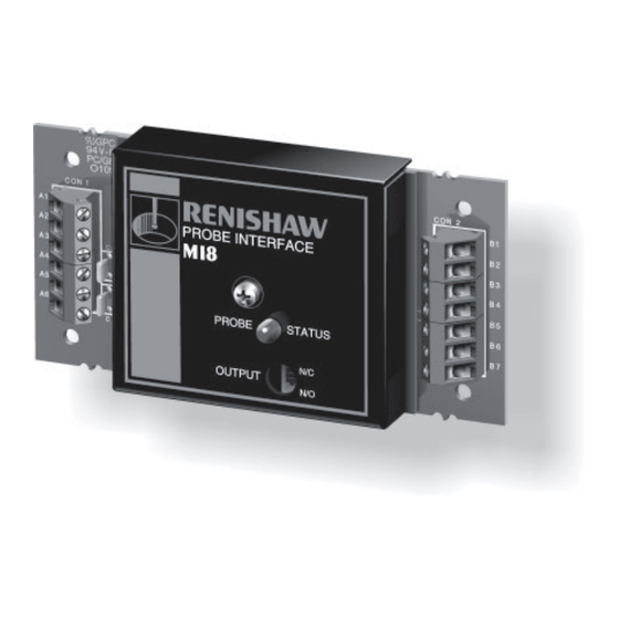
- Page 11 MI 8 INTERFACE UNIT CNC machine tools using a Renishaw probe system for tool setting or workpiece set-up and inspection, require an interface unit, to convert probe signals into an acceptable form for the CNC machine control. The MI 8 interface unit is for probe systems using hard wired signal transmission.
- Page 12 MI 8 FUNCTION The MI 8 interface processes signals from Renishaw Probe status LED hard wired probes and converts them into voltage free Lit when probe is at rest. Unlit indicates probe stylus is deflected or power is off. solid state relay (SSR) output, for transmission to the CNC machine control, which stores work offsets and responds to probe inputs.
- Page 13 50 mA. Alternatively, masked. This can be automatically controlled by an it can be powered from a Renishaw M code (miscellaneous function) from the CNC PSU3 power supply unit.
- Page 14 MI 8 CONNECTIONS dimensions mm (in) 120 (4.72) WIRING - PROBE to MI 8 Use two core screened cable. 92 (3.62) Each core Ø2,5 mm (Ø0.10 in) maximum. Maximum permitted length 30 m (98 ft). 28 (1.1) Core Probe colours type Blue Blue...
- Page 15 M CODE DRIVEN WIRING - MI 8 to CNC CONTROL INHIBIT B1 Use two core screened cable. Each core Ø2,5 mm (Ø0.10 in) maximum. 0 V B2 (0.78) ALTERNATIVE INHIBIT WIRING M CODE DRIVEN EXTERNAL M4 STUDDED SUPPORT OUTPUT ADHESIVE FOOT MOUNTING FOUR HOLES...
- Page 16 Lemo Part no. EGG 1K 303 CNL MI 8 Green interface Renishaw Part no. Screen unit P-CN21-0303 WIRING TABLE FOR CABLE Renishaw cable Part no. A-1016-6451 or similar LP2 probe Plug Wire MI 8 colour pin no. terminal block Screen Blue...
- Page 17 MI 8 OUTPUT SIGNAL The output signal from the Contact bounce Reseat PROBE interface must be compatible STATUS with the machine’s control. OUTPUT OPTIONS Solid state relay (SSR) Move Normally closed (N/C). Trigger clear point Normally open (N/O). At rest Deflected At rest (Teledyne 640-1 or equivalent).
- Page 18 Renishaw plc +44 (0)1453 524524 New Mills, Wotton-under-Edge, +44 (0)1453 524901 Gloucestershire, GL12 8JR uk@renishaw.com United Kingdom www.renishaw.com For worldwide contact details, please visit our main website at www.renishaw.com/contact *H-2000-5015-05-N*...
Need help?
Do you have a question about the H-2000-5015-05-N and is the answer not in the manual?
Questions and answers