Table of Contents

Related Manuals for DENTSPLY Cavitron JET Plus


Summary of Contents for DENTSPLY Cavitron JET Plus
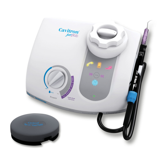
- Page 1 ® ™ Cavitron ® JET Plus ™ Cavitron JET Plus Ultrasonic Scaler & Ultrasonic Scaler & Air Polishing Prophylaxis System Air Polishing Prophylaxis System Installation and Service Manual Please read carefully and completely before operating unit.
-
Page 2: Table Of Contents
SYSTEM SETUP, OPERATION TABLE OF CONTENTS AND TECHNIQUES FOR USE 8.1 Handpiece Setup ..13-14 INTRODUCTION ..3 8.2 Patient Positioning ..14 PRODUCT OVERVIEW . -
Page 3: Introduction
Clinical studies have proven that air Advanced features that make the Cavitron JET Plus a wise polishing is far superior to traditional cup and pumice for investment include a wireless foot control, illuminated stain and plaque removal. -
Page 4: Technical Support
TECHNICAL SUPPORT SECTION 3: Warnings For technical support and repair assistance in the U.S., call • It is the responsibility of the Dental Healthcare the DENTSPLY Professional Cavitron Care Factory Certified Professional to determine the appropriate uses of this Service at 1-800-989-8826, Monday through Friday, 8:00 product and to understand the health of each patient, A.M. -
Page 5: System Precautions
Be sure to clean threads regularly as per Ultrasonics Section 9 System Care. • The Cavitron JET Plus unit works with Cavitron inserts as a system, and was designed and tested to deliver maximum performance for all currently available Cavitron and Cavitron Bellissima™ brand ultrasonic inserts. -
Page 6: Infection Control
Installation Instructions • Incoming power to the system must be 100 volts AC to 240 volts AC, single phase 50/60 Hz capable of Anyone installing a Cavitron JET Plus System should observe supplying 1.0 amps. the following requirements and recommendations. •... -
Page 7: Unpacking The System
• The system has been equipped with a wireless foot • To remove the water line from the Cavitron JET Plus Combination System, turn off the dental office water control which was factory synchronized to operate with the system’s base unit. If your office has more than supply. -
Page 8: Air Supply Line Connection
6.10 Foot Control Synchronization • To remove the air supply line from the Cavitron JET Plus Combination System, turn off the dental office air supply. The wireless foot control supplied with your system has been Disconnect the air supply line from the dental office air factory synchronized with the base unit. - Page 9 Maintain a distance of no more than 10 feet (3m) between the base unit and foot control during the synchronization process. Remove any inserts from the handpiece and adjust the Power Level Control out of Rinse Mode. Turn the Main Power switch to the ON (I) position and wait for the Diagnostic Display graphics to light (refer to Section 7.2).
-
Page 10: Cavitron Jet Plus Combination System Description
SECTION 7: Cavitron JET Plus Combination System Description 7.1 System Controls Ultrasonic Power Level Control Turn knob to select the ultrasonic power level for operation. Turning the knob clockwise JET-Mate™ increases the distance the insert tip moves (stroke) without changing the frequency;... -
Page 11: Diagnostic Display Indicators And Controls
7.2 Diagnostic Display Indicators and Controls Blue Zone Indicator Lights when the Power Level Control is positioned in the Blue Zone of the power scale. Ideal for effective subgingival debridement and greater patient comfort. Rinse Indicator Lights when the Power Level Control is turned Boost Indicator fully counterclockwise. -
Page 12: Handpiece/Cable
7.3 Handpiece / Cable Lavage Control Turn the Lavage Control to select flow rate during system operation. Clockwise increases flow at insert tip, counter- clockwise decreases flow. The flow rate through the handpiece also determines the temperature of the lavage. Lower flow rates produce warmer lavage. -
Page 13: Cavitron Jet Air Polishing Inserts
7.5 Cavitron JET Air Polishing Inserts Air Polishing Insert Nozzle: Prophy Powder Delivery Tube: Insert Heater Rod: Tube-in-a-tube design delivers Directs air/powder flow to insert tip. Heats the delivered water for precise air/water/powder patient comfort. mixture at point of delivery. O-Ring: Seals water when Insert is fully seated in Handpiece. -
Page 14: Patient Positioning
• Lubricate the O-ring on the insert with water before • Turn Power Level Control to select ultrasonic power level placing it into the handpiece. Fully seat insert with a for operation. Clockwise increases system power. gentle push-twist motion. DO NOT FORCE. If using the Power level will increase throughout the full range of the air polishing insert, align the powder delivery tube with control. -
Page 15: Air Polishing Using The Jetshield
Place ejector tube clip around ejector tube and To fill, or refill, the powder bowl: handpiece cable such that the cables drape together • Turn the System OFF. for patient and clinician comfort. (Optional) Place handpiece clip such that the clip is •... -
Page 16: Performing Air Polishing Procedures With Jetshield
8.7 Performing Air Polishing 8.8 Performing Air Polishing Procedures with JetShield Procedures without JetShield NOTE: Refer to the Infection Control card supplied with • Place a 2 x 2 gauze on lip. your System for general procedures to be followed at the beginning of each day and between patients. -
Page 17: Proper Angulation Of The Air Polishing Insert Without Jetshield
Cavitron water supply system. Systems Infection Control Procedures booklet that was With the Cavitron JET Plus Combination System OFF, enclosed with your system. unscrew the powder bowl cap. Verify the powder bowl Disinfect the surfaces of the cabinet, Power Cord, is empty. -
Page 18: Shut-Down Procedures At The End Of The Day
Inspect the handpiece cable for any breaks or tears. to allow the sodium hypochlorite solution to soak in the If using a closed water supply or DualSelect Dispensing lines. As a suggestion, it is recommended that a sign System, check for adequate fluid volumes for the next be placed on the system stating that the SYSTEM IS patient. -
Page 19: Powder Bowl Maintenance
Turn the system’s Main Power Switch to the OFF (0) Although service and repair of the Cavitron JET Plus position. Wait 5 seconds and turn the system back ON. Combination System should be performed by DENTSPLY If problem still exists, replace both “AA”... -
Page 20: Technical Support And Repairs
Section 9.4 Air Supply Line Air Filter Maintenance. Dental office air source should be serviced to eliminate The Cavitron JET Plus Combination Ultrasonic Scaler and the source of the contamination. Air Polishing System is warranted for TWO YEARS from date Symptom: of purchase. -
Page 21: Specifications
SECTION 12: Specifications Electrical Voltage Continuous (100-240 VAC) Current 1.0 Amperes, Maximum Phase Single Frequency 50/60 Hertz Water Pressure 20 to 40 psig (138 to 275 kPa) Air Pressure 65 to 100 psig (448 to 600 kPa) Water Flow Rate Minimum Setting (CCW) <... -
Page 22: Quick Reference Guide
Cavitron JET Plus Ultrasonic Scaler and Air Polishing System QUICK REFERENCE GUIDE Diagnostic Display Illuminates when the Main Power On/Off switch is in the “ON” (l) position. BLUE ZONE Illuminates when the ultrasonic power level control knob is positioned in the Blue Zone of the power scale. The Blue Zone extended low-power range is effective for subgingival debridement and greater patient comfort during definitive therapy. - Page 23 QUICK REFERENCE GUIDE—Troubleshooting SYMPTOM ACTION TAKEN Check that the Main Power Switch is in the ON (I) position, and that the detachable power cord is fully seated in the System will not receptacle on back of system. operate: No Power Check that the system’s power cord plug is fully seated in an appropriate AC wall outlet.
-
Page 24: Analysis
SECTION 16: Cavitron ® JET Plus ™ Troubleshooting and Analysis This troubleshooting section is meant for use by qualified Cavitron ® Service Technicians. SYMPTOMS CAUSES CORRECTIVE MEASURES Cavitron JET Plus™ does not 1. Faulty wall outlet. 1. Check wall outlet and if faulty take necessary ®... - Page 25 Cavitron ® JET Plus ™ Troubleshooting and Analysis, continued This troubleshooting section is meant for use by qualified Cavitron ® Service Technicians. SYMPTOMS CAUSES CORRECTIVE MEASURES Intermittent scaling power or no 1. Insert malfunction. 1. Test with another Cavitron ® insert.
Need help?
Do you have a question about the Cavitron JET Plus and is the answer not in the manual?
Questions and answers