Table of Contents
Advertisement
SERVICE
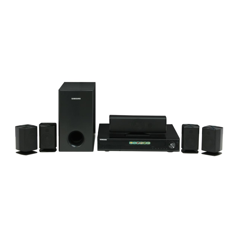
DIGITAL HOME THEATER SYSTEM
HT-Z410
HT-Z510
Refer to the service manual in the GSPN (see the rear cover) for the more information.
DIGITAL HOME
THEATER SYSTEM
Model Name : HT-Z410 / HT-Z510
Model Code : HT-Z410T/XAA
HT-Z510T/XAA
Speaker
HT-Z410
Front
PS-FZ410
Center
PS-CZ410
Rear
PS-RZ410
Subwoofer
PS-WZ410
Manual
1. Precaution
2. Product Specification
3. Disassembly & Reassembly
4. Troubleshooting
5. Exploded View & Part List
6. PCB Diagram
7. Schematic Diagram
HT-Z510
PS-FZ510
PS-CZ510
PS-RZ510
PS-WZ510
CONTENTS
Advertisement
Chapters
Table of Contents

Related Manuals for Samsung HT-Z410


Summary of Contents for Samsung HT-Z410
- Page 1 DIGITAL HOME THEATER SYSTEM Model Name : HT-Z410 / HT-Z510 Model Code : HT-Z410T/XAA HT-Z510T/XAA Speaker HT-Z410 HT-Z510 Front PS-FZ410 PS-FZ510 Center PS-CZ410 PS-CZ510 Rear PS-RZ410 PS-RZ510 Subwoofer PS-WZ410 PS-WZ510 SERVICE Manual CONTENTS DIGITAL HOME THEATER SYSTEM 1. Precaution 2. Product Specification 3.
- Page 2 Asia asia.samsungportal.com Mideast & Africa mea.samsungportal.com © Samsung Electronics Co.,Ltd. Feb. 2008 This Service Manual is a property of Samsung Electronics Printed in Korea Co.,Ltd. Any unauthorized use of Manual can be punished under applicable International and/or domestic law.
-
Page 3: Table Of Contents
4-3 Initialization & Upgrade Methods ..............4-22 5. Exploded View & Part List 5-1 HT-Z410T/XAA Exploded View ................5-2 5-2 HT-Z510T/XAA Exploded View ................5-4 5-3 HT-Z410 Speaker System ................5-6 5-4 HT-Z510 Speaker System ................5-7 5-5 HT-Z410T/XAA Electrical Part List ..............5-8 5-6 HT-Z510T/XAA Electrical Part List ..............5-22... - Page 4 Contents 6. PCB Diagram 6-1 Wiring Diagram ....................6-2 6-2 FRONT PCB Top ....................6-3 6-3 FRONT PCB Bottom ..................6-5 6-4 AMP PCB Top ....................6-6 6-5 AMP PCB Bottom ..................... 6-8 6-6 RF PCB Top .....................6-9 6-7 RF PCB Bottom....................6-11 6-8 MAIN PCB Top ....................
-
Page 5: Precaution
1 and 5.2 megohms. If there is no return path, the measured resistance should be “infinite.” If the resistance is outside these limits, a shock hazard might exist. See Fig. 1-2 Samsung Electronics... - Page 6 . Use replacement components that have the same ratings, especially for flame resistance and dielectric strength specifications. A replacement part that does not have the same safety characteristics as the original might create shock, fire or other hazards. Samsung Electronics...
-
Page 7: Servicing Precautions
8. Always connect a test instrument’s ground lead to the instrument chassis ground before connecting the positive lead; always remove the instrument’s ground lead last. First read the “Safety Precautions” section of this manual. If some unforeseen circumstance creates a conflict between the servicing and safety precautions, always follow the safety precautions. Samsung Electronics... -
Page 8: Precautions For Electrostatically Sensitive Devices (Esds)
9. Minimize body motions when handing unpackaged replacement ESDs. Motions such as brushing clothes together, or lifting a foot from a carpeted floor can generate enough static electricity to damage an ESD. Samsung Electronics... -
Page 9: Product Specification
Product Specification 2. Product Specification 2-1 Product Feature 2-1-1 HT-Z410 Product Feature 1000W Power Output Pure digital HDMI output Video up-scale up to 1080P w/ CEC Expandable to rear wireless. Separate wireless kit is available. USB Host makes easy to access portable devices (Including video) I-pod dock cradle w/OSD, remote control support 2-1-2 HT-Z510 Product Feature 1200W High Power output Pure digital HDMI output w/ CEC Video up-scale up to 1080P US Most popular satellite radio – XM ready (US only) Plays Multi-Channel DVD-Audio USB Host makes easy to access portable devices Rear speakers are wireless For clean & simple set-up I-pod dock cradle w/OSD, remote control support Samsung Electronics... -
Page 10: Specifications
Product Specification 2-2 Specifications 2-2-1 HT-Z410 Specifications Basic Specification Model Name HT-Z410 Power Requirements AC 120V, 60Hz Power Consumption 90 W Weight 11.5 Ibs General Dimensions 16.9 (W) x 17.3 (H) x 2.9 (D) inches Operating Temperature Range +41°F to +95°F Operating Humidity Range 10 % to 75 % Reading Speed: 3.49 ~ 4.06 m/sec. - Page 11 166W Speaker Maximum input 332W 340W 332W Front/Rear: 3.5 x 5.4 x 3.6 inches Dimensions (W x H x D) Center: 11.8 x 4.0 x 3.6 inches Subwoofer: 7.1 x 12.6 x 15.0 inches Front/Rear: 1.3 Ibs Weights Center: 2.1 Ibs Subwoofer: 9.9 Ibs Samsung Electronics...
- Page 12 Pb: 0.70 Vp-p (75 Ω load) Video/ HDMI 1080p, 1080i, 720p, 480p Audio Front speaker output 170W x 2 (3Ω) Center speaker output 180W x 2 (3Ω) Rear speaker output 170W x 2 (3Ω) Subwoofer speaker output 340W (3Ω) Amplifier Frequency range 20Hz ~ 20KHz S/N Ratio 70dB Channel separation 60dB Input sensitivity (AUX) 400mV Samsung Electronics...
- Page 13 340W 360W 680W Front/Rear: 3.5 x 9.0 x 3.6 inches Dimensions (W x H x D) Center: 11.8 x 4.0 x 3.6 inches Subwoofer: 7.9 x 15.7 x 16.5 inches Front: 1.9 Ibs Center: 3.1 Ibs Weights Rear: 1.1 Ibs Subwoofer: 19.0 Ibs Samsung Electronics...
-
Page 14: Specifications Analysis
Product Specification 2-3 Specifications Analysis HT-Z410 HT-Z510 HT-TX500 Model Name Photo RMS (10% THD), REF: 1CH 1000W 1200W 1000W Front: 166W x 2 (3Ω) Front: 170W x 2 (3Ω) Output Center: 170W x 2 (3Ω) Center: 180W x 2 (3Ω) 167W x 5 Power Output Power (ch) Rear: 166W x 2 (3Ω) Rear: 170W x 2 (3Ω) - Page 15 Product Specification HT-Z410 HT-Z510 HT-TX500 Model Name Photo Component Composite Video Inputs S-Video HDMI In Component Composite Video HDMI Out (1080P) Outputs S-Video SCART Out AUX1 AUX1 AUX1 Line In AUX2 AUX2 AUX2 Audio in/out Multi ch Out In (Digital In) (*1) ...
-
Page 16: Accessories
Product Specification 2-4 Accessories 2-4-1 HT-Z410 Supplied Accessories Accessories Item Item code Remark Remote Control AH59-01907E Batteries 4301-000116 Video Cable AH39-40001V FM Antenna AH42-00017A Samsung Service center iPod Dock Package AH97-02650A ASC microphone AH30-00099A Owner’s Instructions AH68-02047C Samsung Electronics... - Page 17 Product Specification 2-4-2 HT-Z510 Supplied Accessories Accessories Item Item code Remark Remote Control AH59-01907F Batteries 4301-000116 Video Cable AH39-40001V FM Antenna AH42-00017A Samsung Service center ASC microphone AH30-00099A Owner’s Instructions AH68-02048C SWA-4000 Accessories Item Item code Remark RESET Wireless Receiver AH97-02731K Module Samsung Service center...
- Page 18 MEMO 2-10 Samsung Electronics...
-
Page 19: Disassembly & Reassembly
Right Side. : BH 3*10 BLACK <Right-Side> <Left-Side> 2) Unscrew the 4 screws from the Rear Side. : BH 3*10 BLACK 3) Lift the Top-Cover to separate it. Be careful not to make any scratches as you remove it. Samsung Electronics... - Page 20 3) Lift the back side of tray in the direction of the arrow to separate it. 4) Separate the cable which is connected to MAIN PCB. In case of pulling up the MAIN PCB cable, it is easier to pull up when pressing the grip. Samsung Electronics...
- Page 21 PCB and MPEG/AMP cable, it is easier to pull up when pressing the grip. 2) Unscrew the 11 screws of BOTTOM cover. : BH 3*6 SILVER 3) Unscrew the 5 screws of rear panel. : BH 3*10 BLACK Samsung Electronics...
- Page 22 Disassembly & Reassembly Part Name Description Description Photo 1) Picture of a disassembled product. Samsung Electronics...
-
Page 23: Troubleshooting
Troubleshooting 4. Troubleshooting 4-1 Checkpoints by Error Mode ..............4-2 4-2 Measures to be taken when the Protection Circuit operates ...4-20 4-3 Initialization & Upgrade Methods ............4-22 Samsung Electronics... -
Page 24: Checkpoints By Error Mode
95 of UIC1 to pin 85 of MICOM (UIC1). If short (0 ohm), Replace MICOM (UIC1) When POWER ON Replace the VFD DRIVER IC for Front PCB, Check for HIGH (ZIC1). voltage (5V) at ZIC; pin16 Samsung Electronics... - Page 25 Troubleshooting Check for Circuit at SMPS Check for VFD 1, 2 ~ 61, 62 PCB-ZD1 (-34V) VFD DC 5V Check for connector from Main PCB to Front PCB; ZCON1 Samsung Electronics...
- Page 26 4, 7, 9 of VD33 is measured at the pin 1 IC14 74LCX157. of IC14. Refer to wave pattern image of Fig. 4-2. Replace the IC14. Check if the pin4 and 5 of CON3 are 3.3V. Samsung Electronics...
- Page 27 Z410: MR28, MR29, MR30, MR31, Replace the resistor for the OR410A, OR410B, OR410C, OR410D. regarding model option. Z510: OR510A, OR510B, OR510C, OR510D, OR510E, OR510F, OR510G, OP510H. Refer to wave pattern image of Fig. 4-4-1 and Fig. 4-4-2. Samsung Electronics...
- Page 28 Check if the PVDD of pin 8, 9, 10 and 11 of J9 are 34.5V. Check if the outputs of the SPK1 and SPK2 of AMP PCB are measured. Refer to wave pattern image of Fig. 4-5. Replace the SPK1 and SPK2 connectors. Samsung Electronics...
- Page 29 Troubleshooting CECJ1 CEIC2 MPEG Page, 7-6 AIC1 MAIN PCB Top Page, 6-12 <Fig. 4-1> Samsung Electronics...
- Page 30 Troubleshooting MIC3 MPEG Page, 7-6 MIC1 MAIN PCB Top Page, 6-12 <Fig. 4-2> Samsung Electronics...
- Page 31 CECJ1 CEIC2 Troubleshooting AIC1 MICOM Page, 7-7 XMIC1 CON1 XIC4 MAIN PCB Top Page, 6-12 <Fig. 4-3> Samsung Electronics...
- Page 32 Troubleshooting AMP Page, 7-4 <Fig. 4-4-1> 4-10 Samsung Electronics...
- Page 33 Troubleshooting SPK2 SPK1 NIC1 UPIC1 AMP PCB Top Page, 6-6 <Fig. 4-4-2> Samsung Electronics 4-11...
- Page 34 Troubleshooting AMP Page, 7-4 SPK2 SPK1 NIC1 AMP PCB Top Page, 6-6 <Fig. 4-5> 4-12 Samsung Electronics...
- Page 35 VIC1 LA73054. pin of VIC1. Replace the VIC1. Check if the pin 3 of CON3 is Check JACK Output. Check if composite video output is measured at the VJ1. Check the VJ1 connectivity and replace it if necessary. Samsung Electronics 4-13...
- Page 36 21, 23, and 25 of VIC1 of VIC1. LA73054. Replace the VIC1. Check if the pin 3 of CON3 is Check JACK Output. Check if composite video output is measured at the VJ1. Check the VJ1 connectivity and replace it if necessary. 4-14 Samsung Electronics...
- Page 37 45, 59 and 74. Refer to wave pattern image of Fig. 4-7. Replace the HIC20 IC. Check the REG1 output pin 2 for VDD1.8V and REG2 output pin 2 for 3.3V. Check the HDCN2 Output. Replace the jack. Samsung Electronics 4-15...
- Page 38 Troubleshooting MPEG Page, 7-6 MIC3 MIC1 IC10 MAIN PCB Top Page, 6-12 <Fig. 4-6> 4-16 Samsung Electronics...
- Page 39 Troubleshooting HDMI Page, 7-8 HIC20 MAIN PCB Top Page, 6-12 <Fig. 4-7> CECJ1 CEIC2 Samsung Electronics 4-17...
- Page 40 Check DVD Signal NO DISC (MJ1 18pin DVD/CD) (MJ1 18pin DVD/CD) DISC ERROR Not Like Not Like Change DECK This This Refer to wave pattern Refer to wave pattern image of Fig. 4-8. image of Fig. 4-8. 4-18 Samsung Electronics...
- Page 41 Troubleshooting Check CD Signal HIC20 Check CD Signal Power On Position Active Check DVD Signal Check DVD Signal MPEG Page, 7-6 Power On High Position Active CECJ1 CEIC2 MAIN PCB Top Page, 6-12 <Fig. 4-8> Samsung Electronics 4-19...
-
Page 42: Measures To Be Taken When The Protection Circuit Operates
-12V +12V <Table 4-1> 4-2-2 Power Protection 1. OTW: Active, IC’s inner temperature exceeds over 150°C. (Under 2.7V, Protection Circuit wills Active) 2. TAS5352 3 PIN: Shout down (Under 2.7V, Protection Circuit wills Active) <Fig. 4-9> 4-20 Samsung Electronics... - Page 43 Troubleshooting 4-2-3 Check AMP in Power Protection You can check AMP malfunction before disassembling Main Unit (Do NOT Insert AC-Cord in AC-Socket) Resistance in using Tester F/R CH 10kΩ CENTER 10kΩ SUBWOOFER 10kΩ <Table 4-2> 5.1CH SPEAKER OUTPUT FRONT R CENTER FRONT L REAR R SUBWOOFER REAR L Samsung Electronics 4-21...
-
Page 44: Initialization & Upgrade Methods
2. Wire to Update connector-look like an oval hole then update start. Required Equipment: Computer, Rom Writer, Connecting Cable, Update Program. Update is available Only OTP type MICOM. <Fig. 4-11 Connecting Rom writer> <Fig. 4-12 Update Program> 4-22 Samsung Electronics... - Page 45 2. Open DISC-TRAY, Press "MENU" button on the Remote Control. 3. Press "8", "9", "5" one by one, then MPEG version will be displayed on the screen and MICOM version on the front display. <Fig. 4-13 Version> Samsung Electronics 4-23...
- Page 46 4. Press "STOP" button of Main Unit 5 seconds more, Display <Fig. 4-14 Connecting USB> Indicator shows ‘INITIALIZE’ then Power go out. 5. Initialization complete. <Fig. 4-15 TV Display (On Updating)> <Fig. 4-16 Update Start> 4-24 Samsung Electronics...
-
Page 47: Exploded View & Part List
Exploded View & Part List 5. Exploded View & Part List 5-1 HT-Z410T/XAA Exploded View ............5-2 5-2 HT-Z510T/XAA Exploded View ............5-4 5-3 HT-Z410 Speaker System..............5-6 5-4 HT-Z510 Speaker System..............5-7 5-5 HT-Z410T/XAA Electrical Part List ............5-8 5-6 HT-Z510T/XAA Electrical Part List ............5-22 Samsung Electronics This Document can not be used without Samsung’s authorization. -
Page 48: Ht-Z410T/Xaa Exploded View
Exploded View & Part List 5-1 HT-Z410T/XAA Exploded View AC080 AR013 CD101 AM020 AS260 HEATS AH400 HOLDE AT090 AH320 AB155 AD502 AC020 AK290 AT100 AC010 AA130 AB260 HOLD AK110 AD503 AD370 AK170 AK420 AR011 This Document can not be used without Samsung’s authorization. Samsung Electronics... - Page 49 PCB-AMP AH92-02784A ASSY PCB-AMP;HT-Z410,AMP ASSY PCB-FRONT AH92-02783A ASSY PCB-FRONT;HT-Z410,FRONT ASSY PCB-MAIN AH92-02782A ASSY PCB-MAIN;HT-Z410,MAIN ASSY PCB-SMPS AH44-00150A SMPS;HT-X50,ORTP-617,AC/DC,1000W/12 TUNER-PACK AH40-00089A TUNER-PACK;KST-ML001FA0-52S,FM,-,-,-,-,- 6003-001375 SCREW-TAPTITE;BH,+,-,B,M3,L8,ZPC(WHT),SW 6003-001561 SCREW-TAPTITE;BH,+,-,B,M3,L6,ZPC(WHT),SW 6003-000280 SCREW-TAPTITE;BH,+,-,B,M3,L25,ZPC(WHT),S 6003-000275 SCREW-TAPTITE;BH,+,-,B,M3,L10,ZPC(BLK),S Samsung Electronics This Document can not be used without Samsung’s authorization.
-
Page 50: Ht-Z510T/Xaa Exploded View
Exploded View & Part List 5-2 HT-Z510T/XAA Exploded View AC080 AR013 CD101 AM020 AS260 HEATS AH400 HOLDE AT090 AH320 AB155 AD502 AC020 AK290 AT100 AC010 AA130 AB260 HOLD AK110 AD503 AD370 AK170 AK420 AR011 This Document can not be used without Samsung’s authorization. Samsung Electronics... - Page 51 PCB-AMP AH92-02787A ASSY PCB-AMP;HT-Z510,AMP ASSY PCB-FRONT AH92-02783A ASSY PCB-FRONT;HT-Z410,FRONT ASSY PCB-MAIN AH92-02786A ASSY PCB-MAIN;HT-Z510,MAIN ASSY PCB-SMPS AH44-00150A SMPS;HT-X50,ORTP-617,AC/DC,1000W/12 TUNER-PACK AH40-00089A TUNER-PACK;KST-ML001FA0-52S,FM,-,-,-,-,- 6003-001375 SCREW-TAPTITE;BH,+,-,B,M3,L8,ZPC(WHT),SW 6003-001561 SCREW-TAPTITE;BH,+,-,B,M3,L6,ZPC(WHT),SW 6003-000280 SCREW-TAPTITE;BH,+,-,B,M3,L25,ZPC(WHT),S 6003-000275 SCREW-TAPTITE;BH,+,-,B,M3,L10,ZPC(BLK),S Samsung Electronics This Document can not be used without Samsung’s authorization.
-
Page 52: Ht-Z410 Speaker System
SPEAKER-REAR LEFT SPK SYSTEM; PS- AH81-03848C RZ410,REAR LEFT SPK SYSTEM,PART FOR PS-Z410 SPEAKER-SUBWOOFER;PS-WZ410,SUBWOOFER Subwoofer AH81-03848D SPK SYSTEM,PART FOR PS-Z410,-,-,-,- SPEAKER;PS-Q40,SPK CORD WIRE,FRONT/SUB W/ Speaker Wire AH81-02177A F:4M,CENTER:3M,REAR:10M,TOTAL:35M(6 PCS),NO CONNECTER,11*0.16,OD:1.8*3.6 This Document can not be used without Samsung’s authorization. Samsung Electronics... -
Page 53: Ht-Z510 Speaker System
RZ510,Rear Left spk system,part for PS-Z510,-,-,-,- AUDIO-RECEIVER-SUBWOOFER SPK SYSTEM; PS- Subwoofer AH81-03845D WZ510,Subwoofer spk system,part for PS-Z510,-,-,-,- SPEAKER-SPK WIRE; SPK WIRE,FRONT Speaker Wire AH81-03845H 4M/2PCS,CENTER 3M/1PCS,SUBWOOFER 4M/2PCS,TOTAL 19M/5PCS,FOR PS-Z510_SERIAL,- Samsung Electronics This Document can not be used without Samsung’s authorization. -
Page 54: Ht-Z410T/Xaa Electrical Part List
AH81-03680A AUDIO-RECEIVER;Shield Cap,1*10,-,-, 2001-000429 R-CARBON;1KOHM,5%,1/8W,AA,TP,1.8X3. AH81-03810A AUDIO-RECEIVER-GRILL FRONT;Grill_Fr 2001-000449 R-CARBON;2.2KOHM,5%,1/8W,AA,TP,1.8X 2001-000472 R-CARBON;2.7KOHM,5%,1/8W,AA,TP,1.8X AH81-03848S SPEAKER-REAR SPK UNIT;REAR SPK UNIT 2001-000522 R-CARBON;22KOHM,5%,1/8W,AA,TP,1.8X3 AH81-03852A A/S PART-HOLE COVER FR;HT-Z410,HIPS 2001-000660 R-CARBON;33KOHM,5%,1/8W,AA,TP,1.8X3 2001-000666 R-CARBON;33OHM,5%,1/8W,AA,TP,1.8X3. AH59-01953B SPEAKER SYSTEM-SUBWOOFER;PS-WZ410,S 1 2001-000734 R-CARBON;4.7KOHM,5%,1/8W,AA,TP,1.8X AH81-03848D SPEAKER-SUBWOOFER;PS-WZ410,SUBWOOFE 1 2001-000780 R-CARBON;470OHM,5%,1/8W,AA,TP,1.8X3 AH81-03455A SPEAKER-FRONT PANEL;PS-Z210,FRONT P This Document can not be used without Samsung’s authorization. Samsung Electronics... - Page 55 14 SNA AH81-02710A WIRE-JUMPER;TIN 0.6t(15.0mm),-,-,-, AH92-02782A ASSY PCB-MAIN;HT-Z410,MAIN ASSY AC1 2401-000651 C-AL;2.2uF,20%,50V,GP,TP,4x7,5 AH81-02712A WIRE-JUMPER;TIN 0.6t(17.5mm),-,-,-, AC10 2203-000491 C-CER,CHIP;2.2nF,10%,50V,X7R,1608 AH81-02716A WIRE-JUMPER;TIN 0.6t(20mm),-,-,-,-, AC11 2401-002112 C-AL;10uF,20%,16V,GP,TP,4x7,2.5 AH81-02717A WIRE-JUMPER;TIN 0.6t(12.5mm),-,-,-, AC12 2203-005148 C-CER,CHIP;100nF,10%,16V,X7R,TP,160 AH81-02763A C-AL;33uF,50V,6.3*11mm,-40 to +85C, AH81-02765A IC-REGULATOR;KA78R08,1A,8V,TO-220F- AC13 2401-001508 C-AL;47uF,20%,16V,GP,TP,6.3x5,5 Samsung Electronics This Document can not be used without Samsung’s authorization.
- Page 56 2007-000084 R-CHIP;4.7Kohm,5%,1/10W,TP,1608 2401-001975 C-AL;47uF,20%,16V,GP,TP,5x11mm,5mm CER9 2007-000084 R-CHIP;4.7Kohm,5%,1/10W,TP,1608 C70 2203-005148 C-CER,CHIP;100nF,10%,16V,X7R,TP,160 C72 2203-005148 C-CER,CHIP;100nF,10%,16V,X7R,TP,160 CN5 3711-000471 HEADER-BOARD TO CABLE;3WALL,4P,1R,2 C73 2401-000414 C-AL;10uF,20%,16V,GP,TP,4x7,5 CON1 3708-001086 CONNECTOR-FPC/FFC/PIC;28P,1.25MM,ST C74 2203-005148 C-CER,CHIP;100nF,10%,16V,X7R,TP,160 CON3 AH39-00824A WIRE HARNESS;HT-Q40,-,-,15,150mm,BL 5-10 This Document can not be used without Samsung’s authorization. Samsung Electronics...
- Page 57 0401-001090 DIODE-SWITCHING;1SS355,80V,100MA,SO HD15 0402-000309 DIODE-RECTIFIER;1SR154-400,400V,1A, HR67 2007-000084 R-CHIP;4.7Kohm,5%,1/10W,TP,1608 HDCN2 3701-001313 CONNECTOR-HDMI;19P,2R,PLUG,ANGLE,AU HR68 2007-000084 R-CHIP;4.7Kohm,5%,1/10W,TP,1608 HIC20 1205-003381 IC-TRANSMITTER;ES7108S,LQFP,80P,12x HR69 2007-000070 R-CHIP;0ohm,5%,1/10W,TP,1608 HR70 2007-000070 R-CHIP;0ohm,5%,1/10W,TP,1608 HL1 2007-000070 R-CHIP;0ohm,5%,1/10W,TP,1608 HR71 2007-000084 R-CHIP;4.7Kohm,5%,1/10W,TP,1608 Samsung Electronics This Document can not be used without Samsung’s authorization. 5-11...
- Page 58 MC124 2401-001975 C-AL;47uF,20%,16V,GP,TP,5x11mm,5mm MC73 2203-006348 C-CER,CHIP;1000nF,10%,25V,X5R,1608 MC125 2203-000189 C-CER,CHIP;100nF,+80-20%,25V,Y5V,16 MC74 2203-006348 C-CER,CHIP;1000nF,10%,25V,X5R,1608 MC75 2401-001938 C-AL;22uF,20%,25V,GP,TP,5x11mm,5mm MC13 2203-001086 C-CER,CHIP;0.0050nF,0.25pF,50V,NP0, MC76 2401-001938 C-AL;22uF,20%,25V,GP,TP,5x11mm,5mm MC14 2203-005148 C-CER,CHIP;100nF,10%,16V,X7R,TP,160 MC143 2203-005148 C-CER,CHIP;100nF,10%,16V,X7R,TP,160 MC77 2203-005148 C-CER,CHIP;100nF,10%,16V,X7R,TP,160 5-12 This Document can not be used without Samsung’s authorization. Samsung Electronics...
- Page 59 2007-000118 R-CHIP;390ohm,5%,1/10W,TP,1608 MR111 2007-000074 R-CHIP;100ohm,5%,1/10W,TP,1608 MR38 2007-000070 R-CHIP;0ohm,5%,1/10W,TP,1608 MR112 2007-000076 R-CHIP;330ohm,5%,1/10W,TP,1608 MR113 2007-000119 R-CHIP;560ohm,5%,1/10W,TP,1608 MR39 2007-000113 R-CHIP;33ohm,5%,1/10W,TP,1608 MR114 2007-000076 R-CHIP;330ohm,5%,1/10W,TP,1608 MR4 2007-000113 R-CHIP;33ohm,5%,1/10W,TP,1608 MR115 2007-000070 R-CHIP;0ohm,5%,1/10W,TP,1608 MR43 2007-000070 R-CHIP;0ohm,5%,1/10W,TP,1608 Samsung Electronics This Document can not be used without Samsung’s authorization. 5-13...
- Page 60 2007-000115 R-CHIP;82ohm,5%,1/10W,TP,1608 OPR9 2007-000115 R-CHIP;82ohm,5%,1/10W,TP,1608 RC51 2401-001938 C-AL;22uF,20%,25V,GP,TP,5x11mm,5mm OPTR1 2007-000070 R-CHIP;0ohm,5%,1/10W,TP,1608 RC52 2203-005065 C-CER,CHIP;1000nF,+80-20%,10V,Y5V,1 OPTR2 2007-000070 R-CHIP;0ohm,5%,1/10W,TP,1608 RC53 2401-000414 C-AL;10uF,20%,16V,GP,TP,4x7,5 RC55 2203-005148 C-CER,CHIP;100nF,10%,16V,X7R,TP,160 PB1 3301-001495 BEAD-SMD;120ohm,2012,2500mA,TP,115o RC56 2203-005148 C-CER,CHIP;100nF,10%,16V,X7R,TP,160 5-14 This Document can not be used without Samsung’s authorization. Samsung Electronics...
- Page 61 2007-000090 R-CHIP;10Kohm,5%,1/10W,TP,1608 UR73 2007-000074 R-CHIP;100ohm,5%,1/10W,TP,1608 UR16 2007-000113 R-CHIP;33ohm,5%,1/10W,TP,1608 UR74 2007-000074 R-CHIP;100ohm,5%,1/10W,TP,1608 UR75 2007-000074 R-CHIP;100ohm,5%,1/10W,TP,1608 UR161 2007-000081 R-CHIP;2.7Kohm,5%,1/10W,TP,1608 UR76 2007-000074 R-CHIP;100ohm,5%,1/10W,TP,1608 UR16A 2007-000090 R-CHIP;10Kohm,5%,1/10W,TP,1608 UR17 2007-000074 R-CHIP;100ohm,5%,1/10W,TP,1608 UR77 2007-000074 R-CHIP;100ohm,5%,1/10W,TP,1608 Samsung Electronics This Document can not be used without Samsung’s authorization. 5-15...
- Page 62 2203-001634 C-CER,CHIP;33nF,10%,50V,X7R,1608 VR37 2007-001167 R-CHIP;75ohm,5%,1/10W,TP,1608 C18SW 2203-005249 C-CER,CHIP;100nF,10%,50V,X7R,1608 VR4 2007-001167 R-CHIP;75ohm,5%,1/10W,TP,1608 C18YL 2203-001634 C-CER,CHIP;33nF,10%,50V,X7R,1608 VR5 2007-001167 R-CHIP;75ohm,5%,1/10W,TP,1608 VR6 2007-001167 R-CHIP;75ohm,5%,1/10W,TP,1608 C18YR 2203-001634 C-CER,CHIP;33nF,10%,50V,X7R,1608 VR7 2007-001167 R-CHIP;75ohm,5%,1/10W,TP,1608 C19CC 2203-005249 C-CER,CHIP;100nF,10%,50V,X7R,1608 5-16 This Document can not be used without Samsung’s authorization. Samsung Electronics...
- Page 63 2203-002793 C-CER,CHIP;1000nF,+80-20%,25V,Y5V,2 FR3 2001-001165 R-CARBON(S);56OHM,5%,1/2W,AA,TP,2.4 C6RR 2203-005249 C-CER,CHIP;100nF,10%,50V,X7R,1608 C6YR 2203-005249 C-CER,CHIP;100nF,10%,50V,X7R,1608 FR4 2007-000097 R-CHIP;47Kohm,5%,1/10W,TP,1608 C7CC 2401-002300 C-AL;47##F,20%,50V,GP,TP,6.3x11,5mm FR5 2007-000084 R-CHIP;4.7Kohm,5%,1/10W,TP,1608 C7FL 2203-005249 C-CER,CHIP;100nF,10%,50V,X7R,1608 FR6 2007-000090 R-CHIP;10Kohm,5%,1/10W,TP,1608 FR7 2007-000134 R-CHIP;33Kohm,5%,1/10W,TP,1608 Samsung Electronics This Document can not be used without Samsung’s authorization. 5-17...
- Page 64 AH27-00064A COIL FILTER;MAX-DT99,10UH,45mOHM,2, R1YR 2007-000070 R-CHIP;0ohm,5%,1/10W,TP,1608 L2YL AH27-00064A COIL FILTER;MAX-DT99,10UH,45mOHM,2, R20CC 2007-002425 R-CHIP;1ohm,5%,1/10W,TP,1608 L2YR AH27-00064A COIL FILTER;MAX-DT99,10UH,45mOHM,2, R21CC 2007-002425 R-CHIP;1ohm,5%,1/10W,TP,1608 R22CC 2007-000070 R-CHIP;0ohm,5%,1/10W,TP,1608 L3CC AH27-00064A COIL FILTER;MAX-DT99,10UH,45mOHM,2, R22SW 2007-000312 R-CHIP;10ohm,5%,1/4W,TP,3216 L4CC AH27-00064A COIL FILTER;MAX-DT99,10UH,45mOHM,2, 5-18 This Document can not be used without Samsung’s authorization. Samsung Electronics...
- Page 65 2203-005249 C-CER,CHIP;100nF,10%,50V,X7R,1608 UAC19 2203-005249 C-CER,CHIP;100nF,10%,50V,X7R,1608 AJACK1 3722-001588 JACK-PHONE;7P,3.6PI,AG,BLK,- UAC2 2203-005249 C-CER,CHIP;100nF,10%,50V,X7R,1608 BRK AH63-01333A SHIELD-JACK;HT-X51H,SPTE,T0.3,-,-,- UAC20 2203-005249 C-CER,CHIP;100nF,10%,50V,X7R,1608 2203-000440 C-CER,CHIP;1nF,10%,50V,X7R,1608 UAC21 2203-005249 C-CER,CHIP;100nF,10%,50V,X7R,1608 2203-000440 C-CER,CHIP;1nF,10%,50V,X7R,1608 UAC22 2203-005249 C-CER,CHIP;100nF,10%,50V,X7R,1608 2203-000440 C-CER,CHIP;1nF,10%,50V,X7R,1608 Samsung Electronics This Document can not be used without Samsung’s authorization. 5-19...
- Page 66 2401-001492 C-AL;47uF,20%,16V,GP,-,5x7mm,2.5 RC23 2203-000440 C-CER,CHIP;1nF,10%,50V,X7R,1608 ZIC1 1003-001541 IC-VFD;PT6315,LQFP,44P,10X10MM,-,-4 RC24 2203-000440 C-CER,CHIP;1nF,10%,50V,X7R,1608 ZJACK1 3722-001588 JACK-PHONE;7P,3.6PI,AG,BLK,- RC25 2402-001042 C-AL,SMD;100uF,20%,16V,GP,TP,6.6x6. RC26 2402-001042 C-AL,SMD;100uF,20%,16V,GP,TP,6.6x6. ZLD1 0601-002482 LED;ROUND,RED/BLUE,5.40x9.50mm,R=6 ZQ1 0501-000002 TR-SMALL SIGNAL;KSA812,PNP,150MW,SO RC33 2203-005148 C-CER,CHIP;100nF,10%,16V,X7R,TP,160 5-20 This Document can not be used without Samsung’s authorization. Samsung Electronics...
- Page 67 RR71 2007-000070 R-CHIP;0ohm,5%,1/10W,TP,1608 RR8 2007-000098 R-CHIP;56Kohm,5%,1/10W,TP,1608 RR9 2007-000090 R-CHIP;10Kohm,5%,1/10W,TP,1608 RR92 2007-000102 R-CHIP;100Kohm,5%,1/10W,TP,1608 RR96 2007-000078 R-CHIP;1Kohm,5%,1/10W,TP,1608 RR97 2007-000309 R-CHIP;10ohm,5%,1/10W,TP,1608 RR98 2007-000090 R-CHIP;10Kohm,5%,1/10W,TP,1608 RR99 2007-000309 R-CHIP;10ohm,5%,1/10W,TP,1608 AH92-02785A ASSY PCB-RF;HT-Z410,RF ASSY AH99-10011L ASSY PCB-RF,m;HT-Z410,RF ASSY Samsung Electronics This Document can not be used without Samsung’s authorization. 5-21...
-
Page 68: Ht-Z510T/Xaa Electrical Part List
2001-000055 R-CARBON;4.7KOHM,5%,1/4W,AA,TP,2.4X AH81-03810A AUDIO-RECEIVER-GRILL FRONT;Grill_Fr 2001-000084 R-CARBON;100Kohm,5%,1/4W,AA,TP,2.4x AH81-03845P SPEAKER-FRONT SPK UNIT;FRONT SPK UN 2001-000241 R-CARBON;1.5KOHM,5%,1/8W,AA,TP,1.8X AH81-03852A A/S PART-HOLE COVER FR;HT-Z410,HIPS 2001-000281 R-CARBON;100OHM,5%,1/8W,AA,TP,1.8X3 AH81-03845K SPEAKER-REAR RIGHT SPK SYSTEM;REAR 2001-000290 R-CARBON;10KOHM,5%,1/8W,AA,TP,1.8X3 AH81-03465A SPEAKER-STAND SAT;PS-Z310,STAND-SAT 2001-000302 R-CARBON;10OHM,5%,1/8W,AA,TP,1.8X3. AH81-03845M SPEAKER-REAR RIGHT SPK SYSTEM;Rear 2001-000325 R-CARBON;120OHM,5%,1/8W,AA,TP,1.8X3 AH81-02478A SPEAKER-FRONT REAR TWEETER;FRONT/RE 1 5-22 This Document can not be used without Samsung’s authorization. Samsung Electronics... - Page 69 AH81-03229A FUSE-CLIP;FC51F,-,-,-,-,-,- AH81-02642A C-FILM MPEF-MYLAR;0.0047uF,100V,5%, AH81-03230A FUSE;10A/AC250V 215xxx,(ceramic),-, AH81-02645A C-FILM MPEF-MPP FILM;0.47uF,275VAC- AH81-03231A VARISTOR;14D471,-,-,-,-,-,- AH81-02648A C-CERAMIC DISK;1000pF,400VAC-Y1,20% AH81-03233A PCB;197*176*1.6t(FR-1),-,-,-,-,-,- AH81-02649A C-CERAMIC DISK;1500pF,400VAC-Y1,20% AH81-03240A HEAT SINK;-,-,-,52.3*16.8*26(HOLE)* AH81-02651A C-AL;6800uF,6.3V,12.5*25mm,-40 to + AH81-03244A HEAT SINK;-,-,-,45*18*28(Hole)*45/S AH81-02657A C-AL;220uF,25V,8*12mm,-40 to +85C,- AH81-03285A CAPACITOR-METAL CAP;ME1000V/152(17. AH81-02666A C-AL;47uF,50V,6.3*11mm,-40 to +105C AH97-02595C ASSY-KITTING PCB;HT-Z510/USA,- Samsung Electronics This Document can not be used without Samsung’s authorization. 5-23...
- Page 70 2007-000074 R-CHIP;100ohm,5%,1/10W,TP,1608 CER27 2007-000074 R-CHIP;100ohm,5%,1/10W,TP,1608 AR33 2007-000098 R-CHIP;56Kohm,5%,1/10W,TP,1608 CER28 2007-000090 R-CHIP;10Kohm,5%,1/10W,TP,1608 AR34 2007-000098 R-CHIP;56Kohm,5%,1/10W,TP,1608 CER3 2007-000071 R-CHIP;22ohm,5%,1/10W,TP,1608 CER30 2007-000090 R-CHIP;10Kohm,5%,1/10W,TP,1608 AR37 2007-000074 R-CHIP;100ohm,5%,1/10W,TP,1608 CER33 2007-000109 R-CHIP;1Mohm,5%,1/10W,TP,1608 AR38 2007-000074 R-CHIP;100ohm,5%,1/10W,TP,1608 5-24 This Document can not be used without Samsung’s authorization. Samsung Electronics...
- Page 71 0406-001128 DIODE-TVS;MLVS-0603-E08,50V,-,- HL53 2007-000070 R-CHIP;0ohm,5%,1/10W,TP,1608 HL7 3301-001495 BEAD-SMD;120ohm,2012,2500mA,TP,115o ESD31 0406-001128 DIODE-TVS;MLVS-0603-E08,50V,-,- HPD1 0401-001099 DIODE-SWITCHING;1N4148WS,75V,150mA, ESD4 0406-001128 DIODE-TVS;MLVS-0603-E08,50V,-,- ESD5 0406-001128 DIODE-TVS;MLVS-0603-E08,50V,-,- HPD2 0401-001099 DIODE-SWITCHING;1N4148WS,75V,150mA, HC26 2203-000626 C-CER,CHIP;0.022nF,5%,50V,C0G,1608 HPQ1 0501-002184 TR-SMALL SIGNAL;KTD1304,NPN,200mW,S Samsung Electronics This Document can not be used without Samsung’s authorization. 5-25...
- Page 72 3301-001495 BEAD-SMD;120ohm,2012,2500mA,TP,115o MC300 2203-000189 C-CER,CHIP;100nF,+80-20%,25V,Y5V,16 IPC1 2401-000042 C-AL;100uF,20%,16V,GP,TP,6.3x7,5 IPC2 2203-005148 C-CER,CHIP;100nF,10%,16V,X7R,TP,160 MC302 2007-000092 R-CHIP;15Kohm,5%,1/10W,TP,1608 IPC3 2203-000783 C-CER,CHIP;0.33nF,5%,50V,C0G,1608 MC308 2203-005148 C-CER,CHIP;100nF,10%,16V,X7R,TP,160 IPC4 2203-000783 C-CER,CHIP;0.33nF,5%,50V,C0G,1608 MC309 2203-005148 C-CER,CHIP;100nF,10%,16V,X7R,TP,160 MC31 2401-000042 C-AL;100uF,20%,16V,GP,TP,6.3x7,5 5-26 This Document can not be used without Samsung’s authorization. Samsung Electronics...
- Page 73 MR195 2007-000078 R-CHIP;1Kohm,5%,1/10W,TP,1608 MIC3 1107-001600 IC-NOR FLASH;MX25L1605A,16Mbit,2Mx8 MR199 2007-000074 R-CHIP;100ohm,5%,1/10W,TP,1608 MJ1 3711-005971 HEADER-BOARD TO BOARD;NOWALL,30P,2R 1 MR2 2007-000070 R-CHIP;0ohm,5%,1/10W,TP,1608 MR200 2007-000074 R-CHIP;100ohm,5%,1/10W,TP,1608 ML10 3301-001495 BEAD-SMD;120ohm,2012,2500mA,TP,115o MR201 2007-000078 R-CHIP;1Kohm,5%,1/10W,TP,1608 ML11 3301-001495 BEAD-SMD;120ohm,2012,2500mA,TP,115o Samsung Electronics This Document can not be used without Samsung’s authorization. 5-27...
- Page 74 MR520 2007-000097 R-CHIP;47Kohm,5%,1/10W,TP,1608 PC8 2401-000042 C-AL;100uF,20%,16V,GP,TP,6.3x7,5 PC9 2401-000042 C-AL;100uF,20%,16V,GP,TP,6.3x7,5 MR530 2007-000074 R-CHIP;100ohm,5%,1/10W,TP,1608 PCBMAIN AH41-01095A PCB-MAIN;HT-Z410,PENNOL,2,0,1.6T,24 MR540 2007-000090 R-CHIP;10Kohm,5%,1/10W,TP,1608 MR55 2007-000090 R-CHIP;10Kohm,5%,1/10W,TP,1608 PIC2 1203-002935 IC-POSI.ADJUST REG.;AIC1117ACE,TO-2 MR58 2007-000084 R-CHIP;4.7Kohm,5%,1/10W,TP,1608 PR10 2007-000293 R-CHIP;100ohm,5%,1/4W,TP,3216 5-28 This Document can not be used without Samsung’s authorization. Samsung Electronics...
- Page 75 2007-000122 R-CHIP;1.2Kohm,5%,1/10W,TP,1608 UR105 2007-000084 R-CHIP;4.7Kohm,5%,1/10W,TP,1608 RR78 2007-000078 R-CHIP;1Kohm,5%,1/10W,TP,1608 RR79 2007-000122 R-CHIP;1.2Kohm,5%,1/10W,TP,1608 UR11 2007-000107 R-CHIP;470Kohm,5%,1/10W,TP,1608 RR80 2007-000078 R-CHIP;1Kohm,5%,1/10W,TP,1608 UR115 2007-000074 R-CHIP;100ohm,5%,1/10W,TP,1608 RR84A 2007-000090 R-CHIP;10Kohm,5%,1/10W,TP,1608 UR115A 2007-000090 R-CHIP;10Kohm,5%,1/10W,TP,1608 UR12 2007-000109 R-CHIP;1Mohm,5%,1/10W,TP,1608 Samsung Electronics This Document can not be used without Samsung’s authorization. 5-29...
- Page 76 2007-000074 R-CHIP;100ohm,5%,1/10W,TP,1608 VR15 2007-001167 R-CHIP;75ohm,5%,1/10W,TP,1608 UR67 2007-000074 R-CHIP;100ohm,5%,1/10W,TP,1608 VR16 2007-001167 R-CHIP;75ohm,5%,1/10W,TP,1608 UR68 2007-000074 R-CHIP;100ohm,5%,1/10W,TP,1608 VR17 2007-001167 R-CHIP;75ohm,5%,1/10W,TP,1608 VR18 2007-001167 R-CHIP;75ohm,5%,1/10W,TP,1608 UR69 2007-000074 R-CHIP;100ohm,5%,1/10W,TP,1608 VR2 2007-001167 R-CHIP;75ohm,5%,1/10W,TP,1608 UR7 2007-000074 R-CHIP;100ohm,5%,1/10W,TP,1608 5-30 This Document can not be used without Samsung’s authorization. Samsung Electronics...
- Page 77 2203-005249 C-CER,CHIP;100nF,10%,50V,X7R,1608 C15YR 2203-005249 C-CER,CHIP;100nF,10%,50V,X7R,1608 C37CC 2305-000407 C-FILM,LEAD-PEF;470nF,5%,100V,TP,10 C16RL 2203-000257 C-CER,CHIP;10nF,10%,50V,X7R,TP,1608 C3FL 2203-005249 C-CER,CHIP;100nF,10%,50V,X7R,1608 C16SW 2203-000257 C-CER,CHIP;10nF,10%,50V,X7R,TP,1608 C3YL 2203-005249 C-CER,CHIP;100nF,10%,50V,X7R,1608 C4RL 2203-005249 C-CER,CHIP;100nF,10%,50V,X7R,1608 C16YL 2203-000257 C-CER,CHIP;10nF,10%,50V,X7R,TP,1608 C4SW 2203-005249 C-CER,CHIP;100nF,10%,50V,X7R,1608 Samsung Electronics This Document can not be used without Samsung’s authorization. 5-31...
- Page 78 FQ2 0501-000341 TR-SMALL SIGNAL;KSC1623-L,NPN,200mW IC1Y 1201-002673 IC-AUDIO AMP;TAS5352DDV,HTSSOP,44P, FQ3 0501-000422 TR-SMALL SIGNAL;KTA1273,PNP,-30V,-3 AH39-00940A WIRE HARNESS;HT-X50,-,-,11,50mm,BLA 3708-001086 CONNECTOR-FPC/FFC/PIC;28P,1.25MM,ST FQ4 0504-000128 TR-DIGITAL;-,NPN,200MW,22K/22K,SOT- L1FL AH27-00064A COIL FILTER;MAX-DT99,10UH,45mOHM,2, FR1 2001-000022 R-CARBON(S);33OHM,5%,1/2W,AA,TP,2.4 FR10 2007-000097 R-CHIP;47Kohm,5%,1/10W,TP,1608 L1RL AH27-00064A COIL FILTER;MAX-DT99,10UH,45mOHM,2, 5-32 This Document can not be used without Samsung’s authorization. Samsung Electronics...
- Page 79 3716-001131 TERMINAL-BLOCK;SOLDER,6P,-,-,- R13YL 2007-002425 R-CHIP;1ohm,5%,1/10W,TP,1608 UAC1 2401-000414 C-AL;10uF,20%,16V,GP,TP,4x7,5 R13YR 2007-002425 R-CHIP;1ohm,5%,1/10W,TP,1608 R14SW 2007-000463 R-CHIP;18ohm,5%,1/10W,TP,1608 UAC11 2401-001355 C-AL;470uF,20%,10V,GP,TP,8x11.5mm,5 R150 2007-000097 R-CHIP;47Kohm,5%,1/10W,TP,1608 UAC12 2203-005249 C-CER,CHIP;100nF,10%,50V,X7R,1608 R15SW 2007-000463 R-CHIP;18ohm,5%,1/10W,TP,1608 UAC13 2203-005249 C-CER,CHIP;100nF,10%,50V,X7R,1608 Samsung Electronics This Document can not be used without Samsung’s authorization. 5-33...
- Page 80 UAR9 2007-000090 R-CHIP;10Kohm,5%,1/10W,TP,1608 USC1 2203-005249 C-CER,CHIP;100nF,10%,50V,X7R,1608 UPIC1 1204-002627 IC-MODULATOR;PS9829B,LQFP,100P,14x1 USC2 2401-001492 C-AL;47uF,20%,16V,GP,-,5x7mm,2.5 UPIC2 AH14-10004R IC-CMOS LOGIC;74HCU04,-,SOP,14P,-,- VOL1 3406-001047 SWITCH-ROTARY;5V DC,0.5mA,-,12mm UPX1 2801-004354 CRYSTAL-UNIT;12.288MHZ,30PPM,ATS-49 VR1 2007-000090 R-CHIP;10Kohm,5%,1/10W,TP,1608 AH99-10011N ASSY PCB-AMP,m;HT-Z510,AMP ASSY VR2 2007-000090 R-CHIP;10Kohm,5%,1/10W,TP,1608 5-34 This Document can not be used without Samsung’s authorization. Samsung Electronics...
- Page 81 2007-000078 R-CHIP;1Kohm,5%,1/10W,TP,1608 0504-000128 TR-DIGITAL;-,NPN,200MW,22K/22K,SOT- 0501-000632 TR-SMALL SIGNAL;2SB1197K,PNP,200mW, RR67 2007-000309 R-CHIP;10ohm,5%,1/10W,TP,1608 0501-000632 TR-SMALL SIGNAL;2SB1197K,PNP,200mW, RR68 2007-000309 R-CHIP;10ohm,5%,1/10W,TP,1608 R101 2007-000082 R-CHIP;3.3Kohm,5%,1/10W,TP,1608 RR7 2007-000098 R-CHIP;56Kohm,5%,1/10W,TP,1608 RR70 2007-000070 R-CHIP;0ohm,5%,1/10W,TP,1608 RB1 3301-001495 BEAD-SMD;120ohm,2012,2500mA,TP,115o RR71 2007-000070 R-CHIP;0ohm,5%,1/10W,TP,1608 Samsung Electronics This Document can not be used without Samsung’s authorization. 5-35...
- Page 82 AH81-02634A DIODE-BRLDGE RECTLFLERS;TS4B05G,600 AH81-02635A DIODE-ZENER;1N5242B,500mW,12V,DO-35 AH81-02662A C-AL;220uF,25V,8*12mm,-40 to +105C, AH81-02665A C-AL;4.7uF,50V,5*11mm,-40to +105C,- AH81-02667A C-AL;2200uF,50V,16*35mm,-40 to +105 AH81-02763A C-AL;33uF,50V,6.3*11mm,-40 to +85C, AH81-02816A C-AL;1uF,50V,5*11mm,-40 to +85C,-,- AH81-03496A C-AL;470uF,10V,6.3X11mm,-,-,-,- AH81-04177M A/S-RX PCB;SWA-4000,-,-,-,-,-,- AH81-04177N A/S-LED PCB ASSY;SWA-4000,-,-,-,-,- 0601-001238 LED;ROUND,RED,3.1mm,697nm,3.8x5.2m 0601-001432 LED;ROUND,BLUE,3mm,455nm AH81-04177P A/S-ASSY FRONT;SWA-4000,-,-,-,-,-,X AH59-01907F REMOCON-ASSY;HT-Z510/EXP,SAMSUNG,23 AH69-02154C MASTER CARTON;HT-Z410,PAPER,T7,W515 1.02 SNA 5-36 This Document can not be used without Samsung’s authorization. Samsung Electronics...
-
Page 83: Pcb Diagram
PCB Diagram 6. PCB Diagram 6-1 Wiring Diagram....................6-2 6-2 FRONT PCB Top ....................6-3 6-3 FRONT PCB Bottom ..................6-5 6-4 AMP PCB Top ....................6-6 6-5 AMP PCB Bottom ..................... 6-8 6-6 RF PCB Top ...................... 6-9 6-7 RF PCB Bottom ....................6-11 6-8 MAIN PCB Top ....................6-12 6-9 MAIN PCB Bottom .................... 6-15 6-10 SMPS PCB Top ....................6-16 Samsung Electronics... -
Page 84: Wiring Diagram
FAN_SD FAN_SD TRACK TRACK SPNN SPNN SPNP SPNP DECK ASSY MAIN ASSY VFD-DC VFD-DC VFD+DC VFD+DC U_GND U_GND +5.6V +5.6V P-ON/OFF P-ON/OFF SMPS ASSY P-SENSE P-SENSE D_GND D_GND D_GND D_GND 3.3V 3.3V 3.3V 3.3V M_GND M_GND FRONT ASSY Samsung Electronics... -
Page 85: Front Pcb Top
PCB Diagram 6-2 FRONT PCB Top ACON1 CONU1 ZIC1 CN24 Samsung Electronics... - Page 86 Front Control Connector USB Connector AUX1 Connector Pin No. Signal Pin No. Signal Pin No. Signal HP-R AGND DATA- HP-L DATA+ HPSEN USB_GND REMO KEY1 KEY2 VP_GND VFD DC -VFD DC VOL DOWN VOL UP DATA ST-LED 5.6V DIMMER +12V ASC_SENS Samsung Electronics...
-
Page 87: Front Pcb Bottom
PCB Diagram 6-3 FRONT PCB Bottom ACON1 CONU1 CN24 Samsung Electronics... -
Page 88: Amp Pcb Top
PCB Diagram 6-4 AMP PCB Top SPK2 SPK1 NIC1 UPIC1 Samsung Electronics... - Page 89 2 J3 AMP Signal Connector Power-AMP Connector Pin No. Signal Pin No. Signal H/P_R +12V H/P_L S_GND A_GND -12V 5152_SD 5152_RESET 3.3V_GND +3.3V EX_MUTE PVDD D_GND PVDD PVDD PVDD 9829_RESET TSD2(SW_C) TSD1(REAR) TSD0(FRONT) TBCK D_GND +12V A_GND FAN_SENSE FAN_POWER FAN_SD Samsung Electronics...
-
Page 90: Amp Pcb Bottom
PCB Diagram 6-5 AMP PCB Bottom Samsung Electronics... -
Page 91: Rf Pcb Top
PCB Diagram 6-6 RF PCB Top RCN2 IC11 RCN1 Samsung Electronics... - Page 92 PCB Diagram 6-6-1 Pin Connection 1 RCN2 RF Signal Connector Pin No. Signal RFGND DVDLD CDLD DVD/CD_PD HOMESW MOCTL PUHAF R_5V VD33RF DVD/CD MVCC MDGND PU_CHECK MVREF SPINDLE FOCUS SLEGN TRACK SPNN SPNP 6-10 Samsung Electronics...
-
Page 93: Rf Pcb Bottom
PCB Diagram 6-7 RF PCB Bottom MJ4_1 Samsung Electronics 6-11... -
Page 94: Main Pcb Top
PCB Diagram 6-8 MAIN PCB Top HIC20 TP10 MIC3 MIC1 IC10 CECJ1 CEIC2 TP11 TP12 AIC1 UIC1 XMIC1 CON1 MIC12 XIC4 MIC11 CON3 6-12 Samsung Electronics... - Page 95 DVD/CD RESET TBCK M_GND 5.6V MVCC DIMMER D_GND MDGND DATAI 3.3V PU_CHECK DATAO 3.3V +12V +12V CLOCK D_GND ASC_SENS A_GND MVREF D_GND FAN_SENSE SPINDLE P-SENSE FOCUS P-ON/OFF FAN_POWER SLEGN +5.6V FAN_SD TRACK U_GND SPNN VFD+DC SPNP VFD-DC Samsung Electronics 6-13...
- Page 96 PCB Diagram 6-8-2 Test Point Wave Form TP10 TP11 TP12 6-14 Samsung Electronics...
-
Page 97: Main Pcb Bottom
PCB Diagram 6-9 MAIN PCB Bottom HDCN2 CECJ1 CON1 CON3 Samsung Electronics 6-15... -
Page 98: Smps Pcb Top
PCB Diagram 6-10 SMPS PCB Top ICM1 6-16 Samsung Electronics... -
Page 99: Schematic Diagram
7-2 FRONT ....................... 7-3 7-3 AMP ........................7-4 7-4 RF ........................7-5 7-5 MPEG ........................ 7-6 7-6 MICOM ....................... 7-7 7-7 HDMI ........................7-8 7-8 IPOD ........................7-9 7-9 SMPS ......................... 7-10 Samsung Electronics This Document can not be used without Samsung’s authorization. -
Page 100: Overall Block Diagram
The AMP Block consists of PS9829B, 3 TAS5352, and other passive component. PS9829B transforms PCM to PWM data and TAS5352 amplifies the signal to drive almost 170W per channel. This Document can not be used without Samsung’s authorization. Samsung Electronics... -
Page 101: Front
Schematic Diagram 7-2 FRONT POWER Samsung Electronics This Document can not be used without Samsung’s authorization. -
Page 102: Amp
Schematic Diagram 7-3 AMP POWER AUDIO This Document can not be used without Samsung’s authorization. Samsung Electronics... - Page 103 Schematic Diagram 7-4 RF Samsung Electronics This Document can not be used without Samsung’s authorization.
-
Page 104: Mpeg
Schematic Diagram 7-5 MPEG POWER AUDIO COMPOSITE COMPONENT TP11 TP11 TP12 TP12 This Document can not be used without Samsung’s authorization. Samsung Electronics... -
Page 105: Micom
Schematic Diagram 7-6 MICOM POWER Samsung Electronics This Document can not be used without Samsung’s authorization. -
Page 106: Hdmi
Schematic Diagram 7-7 HDMI TP10 POWER TP10 This Document can not be used without Samsung’s authorization. Samsung Electronics... -
Page 107: Ipod
Schematic Diagram 7-8 IPOD Samsung Electronics This Document can not be used without Samsung’s authorization. -
Page 108: Smps
1uF/50V UF4004 UF4004 RA11 821 M 470K 272 M 0.22 2W 0.15 2W 150 F 1.5K RA10 CA10 UF4004 47 F 50V/47uF(105) KA431AZ PCA4A ZDA1 1N5235B PC817 JUMPER 7-10 This Document can not be used without Samsung’s authorization. Samsung Electronics...