
Related Manuals for IPUX ICS1330

Summary of Contents for IPUX ICS1330
- Page 1 Wireless Pan-Tilt MPEG4/MJPEG Network Camera Advanced Installation Guide Version 1.3...
-
Page 2: Preface
REFACE Thank you for purchasing ICS1330, a powerful dual-codec wireless network camera with the 2-way audio function that provides the high- quality image and on-the-spot audio via the Internet connection. The Infrared LEDs and light sensor enable the camera to capture images even in the dark environment. -
Page 3: Table Of Contents
Contents P r e f a c e ..............1 C h a p t e r 1 I n tr o d u c t i o n T o Y o u r C a m e r a . -
Page 4: Chapter 1 I N Tr O D U C T I O N T O Y O U R C A M E R A
HAPTER NTRODUCTION AMERA 1.1 Checking the Package Contents Check the items contained in the package carefully. You should have the following: One ICS1330 One AC Power Adapter One External Antenna One Wall Mount Kit One GPIO Connector ... -
Page 5: Getting To Know Your Camera
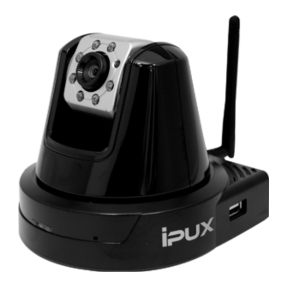
1.2 Getting to Know Your Camera Light Sensor is used to trigger on and off the Infrared LEDs according the environmental light level. Antenna Infrared LEDs (x7) allow your camera to capture clear image in a dark environment. Lens Assembly Power LED indicates the camera is powered on with... -
Page 6: Rear View
Ethernet Cable Connector connects the network cable, which supports the NWay protocol so that the camera External Antenna can detect the network Connector connects the speed automatically. external antenna. DC Power Connector connects the AC power adapter, in order to supply power to the camera. -
Page 7: Features And Benefits
1.3 Features and Benefits MPEG4/MJPEG Dual-codec Supported The camera provides you with excellent images by the MPEG4/ MJPEG dual-codec selectable technology, allowing you to adjust image size and quality, and bit rate according to the networking environment. 2-way Audio Capability The built-in microphone of the camera provides on-the-spot audio via the Internet, allowing you to monitor the on-site voice. - Page 8 Supports Multiple Profiles The camera supports multiple profiles simultaneously, so that you can separately set up different image settings (such as image quality and frame rate) for the three video types of the camera: MPEG4, MJPEG, and 3GPP. I/O Connectors Provided The camera provides the I/O connectors on the rear panel (IN/OUT), which provide the physical interface to send and receive digital signals to a variety of external alarm devices.
-
Page 9: System Requirement
1.4 System Requirement Networking LAN: 10Base-T Ethernet or 100Base-TX Fast Ethernet. WLAN: IEEE 802.11b/g/n Accessing the Camera using Web Browser Platform: Microsoft® Windows® 2000/XP/Vista/Win7 CPU: Intel Pentium III 800MHz or above RAM: 512MB Resolution: 800x600 or above User Interface: Microsoft® Internet Explorer 6.0 or above Apple Safari 2 or above Mozilla Firefox 2.00 or above Google Chrome... -
Page 10: Installing The Wall Mount Kit
HAPTER ARDWARE NSTALLATION 2.1 Installing the Wall Mount Kit The camera comes with a Wall Mount Kit, which allows you to place your camera anywhere by mounting the camera through the three screw holes located in the base of the Wall Mount Kit. Screw Wall Mount Kit Screw... -
Page 11: Connecting The Camera To Lan/Wlan
2.2 Connecting the Camera to LAN/WLAN Use the provided Ethernet cable to connect the camera to your local area network (LAN). When you connect the AC power adapter, the camera is powered on automatically. You can verify the power status from the Power LED on the front panel of the camera. -
Page 12: Applications Of The Camera
2.3 Applications of the Camera The camera can be applied in multiple applications, including: Monitor local and remote places and objects via Internet or Intranet. Capture still images and video clips remotely. Upload images or send email messages with the still images attached. -
Page 13: Using Ipfinder
HAPTER CCESSING AMERA 3.1 Using IPFinder The camera comes with a conveniently utility, IPFinder, which is included in the Installation CD-ROM, allowing you to search the camera on your network easily. 1. Insert the Installation CD-ROM into your computer’s CD-ROM drive to initiate the Auto-Run program. -
Page 14: Accessing To The Camera
3.2 Accessing to the Camera Whenever you want to access the camera: 1. Since the default configuration of the camera is DHCP mode enabled, you are recommended to launch IPFinder to search the IP address that is assigned to the camera by the DHCP server, and then click Link to access the camera via the Web browser. - Page 15 After you login into the Web Configuration of the camera, the main page will appear as below: Zoom In Buttons Nightmode Button Language Camera Information Live View/Setup Switch Compression Buttons Live View Image Pan/Tilt Buttons Function Buttons The main page of the Web Configuration provides you with many useful information and functions, including: ...
- Page 16 right-clicking your mouse on the Live View area. The position where you right-clicked will be displayed in the central part of Live View area. Zoom In Buttons – Click the buttons to zoom in the live view image by 1x, 2x, and 3x. ...
- Page 17 Auto Patrol button controls the camera to automatically scan the preset positions once. Click Stop to stop patrolling. Click the Number button (1~8) to move the camera lens to the preset position immediately. To set up the preset positions, move the camera lens by clicking the Left/Right/Up/Down buttons to the desired position first, then select the number (1~8) from the pull- down list and click the Apply button.
-
Page 18: Configuring The Ip Address Of The Pc
3.3 Configuring the IP Address of the PC If you are failed to access to the camera, please check the IP address of your computer. When you connect the camera to your computer directly to proceed with configuration of the camera, you need to set up the IP addresses to be in the same segment for the two devices to communicate. -
Page 19: Using The Web Configuration
HAPTER ONFIGURING AMERA 4.1 Using the Web Configuration You can access and manage the camera through the Web browser and the provided software application UltraView Pro. This chapter describes the Web Configuration, and guides you through the configuration of the camera by using the Web browser. To configure the camera, click Setup on the main page of Web Configuration. -
Page 20: Using Smart Wizard
4.2 Using Smart Wizard The camera’s Smart Wizard lets you configure your camera easily and quickly. The wizard will guide you through the necessary settings with detailed instructions on each step. To start the wizard, click Smart Wizard in the left menu bar. Step 1. - Page 21 Step 3. Email Settings Enter the required information to be able to send email with image. Step 4. Wireless Networking Complete the required settings for wireless networking. - 20 -...
- Page 22 Step 5. Confirm Settings This step shows the configuration of your camera. When you confirm the settings, click Apply to finish the wizard and reboot the camera. Otherwise, click Prev to go back to the previous step(s) and change the settings; or click Cancel to end the wizard and discard the changes.
-
Page 23: Basic Setup
4.3 Basic Setup The Basic menu contains three sub-menus that provide the system settings for the camera, such as the Camera Name, Location, Date & Time, and User management. Basic >> System Basic - Camera Name: Enter a descriptive name for the camera. - Location: Enter a descriptive name for the location used by the camera. - Page 24 Basic >> Date & Time - TimeZone: Select the proper time zone for the region from the pull-down menu. - Synchronize with PC: Select this option and the date & time settings of the camera will be synchronized with the connected computer.
-
Page 25: General User
Basic >> User Administrator To prevent unauthorized access to the camera’s Web Configuration, you are strongly recommend to change the default administrator password. Type the administrator password twice to set and confirm the password. General User - User Name: Enter the user’s name you want to add to use the camera. - Page 26 Guest - User Name: Enter the guest’s name you want to add to use the camera. - Password: Enter the password for the new guest. - UserList: Display the existing guests of the camera. To delete a user, select the one you want to delete and click Delete. NOTE The “General User”...
-
Page 27: Network Settings
4.4 Network Settings The Network menu contains three sub-menus that provide the network settings for the camera, such as the IP Setting, DDNS Setting, IP Filter, and Wireless network. Network >> Network - 26 -... - Page 28 IP Setting This item allows you to select the IP address mode and set up the related configuration. The default setting is DHCP mode enabled. - DHCP: Select this option when your network uses the DHCP server. When the camera starts up, it will be assigned an IP address from the DHCP server automatically.
- Page 29 DDNS Setting With the Dynamic DNS feature, you can assign a fixed host and domain name to a dynamic Internet IP address. Select the Enable option to enable this feature. Then, select the Provider from the pull-down list and enter the required information in the Host Name, User Name, and Password boxes.
- Page 30 Network >> IP Filter The IP Filter setting allows the administrator of the camera to limit the users within a certain range of IP addresses to access the camera. Start/End IP Address Assign a range of IP addresses that are not allowed to access the camera by entering the Start IP address and End IP address.
- Page 31 Network >> Wireless Setting The camera supports WLAN while you use the wireless network. Select the Enable option to enable this feature. - Network ID (SSID}: Keep the default setting of this option to connect the camera to any access point under the infrastructure network mode.
- Page 32 List of searching results - Wireless Mode: Select the type of wireless communication for the camera: Infrastructure or Ad-Hoc. - Channel: Select the appropriate channel from the list. - Authentication: Select the authentication method to secure the camera from being used by unauthorized user: Open, Shared-key, WPA-PSK, and WPA2-PSK.
- Page 33 Format: Once you enable the Encryption feature, you need to determine the encryption format by selecting ASCII or HEX. ASCII format causes each character you type to be interpreted as an eight-bit value. Hex format causes each pair of characters you type to be interpreted as an eight-bit value in hexadecimal (base 16) notation.
- Page 34 Network >> Wireless >> WPS Setting WPS (Wi-Fi Protected Setup) sets a new standard of Wi-Fi security, providing a simplified secure network setup solution for the end users. WPS can be enabled by the following two options: 1. PIN Mode 2.
-
Page 35: Device Status
c. Click the Connect button to start WPS function of the camera. d. You need to enter the PIN Code displayed on the camera to the router (or access point) within 120 seconds to complete the setup. - PBC Mode: The PBC (Push-Button-Configuration) mode builds the connection by simply pressing a button on the device. -
Page 36: Pan/Tilt Settings
4.5 Pan/Tilt Settings The Pan/Tilt menu allows you to configure the pan/tilt functions of the camera. Pan & Tilt >> Pan & Tilt Settings - Pan/Tilt Calibration: Click Calibration to calibrate the position of the camera lens. - Pan Steps: Set the changing range (1~20 degrees) when you click the Left/Right button. -
Page 37: Setting Up Video & Audio
4.6 Setting up Video & Audio The Video & Audio menu contains three sub-menus that provide the video and audio settings for the camera. Video & Audio >> Camera Image Setting - Brightness: Adjust the brightness level from 0 ~ 100. - Contrast: Adjust the contrast level from 0 ~ 100. -
Page 38: Overlay Setting
- Mirror: Select the Horizontal option to mirror the image horizontally. Select the Vertical option to mirror the image vertically. - Light Frequency: Select the proper frequency according to the camera’s location: 50Hz, 60Hz, or Outdoor. Overlay Setting - Includes Date & Time: Select this option to display the date & time stamp on the live view image. - Page 39 Video & Audio >> Video MPEG4 - Video Resolution: Select the desired video resolution from the three formats: VGA, QVGA and QQVGA. The higher setting (VGA) obtains better video quality while it uses more resource within your network. - Video Quality: Select the desired image quality from five levels: Lowest, Low, Medium, High, and Highest.
- Page 40 - Video Quality: Select the desired image quality from five levels: Lowest, Low, Medium, High, and Highest. - Frame Rate: Select Auto or a proper setting depending on your network status. NOTE The camera supports both MPEG4 and MJPEG compression. MJPEG capture the images in JPEG format, which require higher bandwidth to view smooth video.
- Page 41 Video & Audio >> Audio Camera Microphone In Select the Enable option to enable the camera’s audio function, so that you can receive the on-site sound and voice from the camera. Camera Speaker Out Select the Enable option to enable the camera’s external speaker function, so that the connected speaker can play the sound and voice through the camera.
-
Page 42: Event Server Configuration
4.7 Event Server Configuration The Event Server menu contains three sub-menus that allow you to upload images to FTP, send emails that include still images, and store the images to a NAS system. When you complete the required settings for FTP, Email, or Network Storage, click Test to test the related configuration is correct or not. - Page 43 - Passive Mode: Select the Enable option to enable passive mode. - FTP Upload with: Select upload to FTP with one snapshot image or a series image in pre-event/post-event time when event triggered. NOTE Due to the network environment, the camera may not upload number of images that you set.
- Page 44 Event Server Setting >> Email - SMTP Server Address: Enter the mail server address. For example, mymail.com. - Sender Email Address: Enter the email address of the user who will send the email. For example, John@mymail.com. - Sender User Name: Enter the user name to login the mail server.
- Page 45 Event Server Setting >> Network Storage - Samba Server Address: Enter the IP address of the Network Storage server. - Share: Assign the folder on the Network Storage server to share the files to users. - Path: Assign the path for uploading the files on the Network Storage server.
-
Page 46: Motion Detect
4.8 Motion Detect The Motion Detect menu contains the command and option that allow you to enable and set up the motion detection feature of the camera. The camera provides two detecting areas. To enable the detecting area, select Window 1 or 2 from the pull- down list, and then select Enable. -
Page 47: Event Config
4.9 Event Config The Event Config menu contains five sub-menus that provide the commands to configure event profiles. Event Configuration >> General Setting - Snapshot/Recording Subfolder: You can assign a descriptive name for the subfolder to save the captured image/video files. Otherwise, leave this option blank to use the default setting. - Page 48 Event Configuration >> Arrange Schedule Profile This sub-menu displays the scheduled profile(s). To customize the profile, click Add and then enter a descriptive name for the profile in the prompt dialog window. After entering the profile name, click OK and the profile is added to the Schedule Profiles list. To delete the profile, select the profile in the list and click Delete.
- Page 49 Event Configuration >> Motion Detect Trigger Select the Enable option to enable the motion detect trigger function of the camera, so that you can set Trigger Out function or send captured images within the detecting area to the FTP server, email receiver, Network Storage server, or the connected USB device.
- Page 50 Event Configuration >> Schedule Trigger You can separately configure the schedule for trigger function of the camera by Email, FTP, or Network Storage. Select the Enable option on each item, and then select a Schedule Profile from the pull-down list and set the Interval time. NOTE If the setting value of the Network Storage Recording Time Per Event option in General Setting is longer than the...
- Page 51 Event Configuration >> GPIO Trigger Select the Enable option to enable the GPIO trigger function of the camera, so that you can set Trigger Out function or send captured images within the detecting area to the FTP server, email receiver, Network Storage server, or the connected USB device.
-
Page 52: Tools
4.10 Tools The Tools menu provides the commands that allow you to restart or reset the camera. You can also backup and restore your configuration, and upgrade the firmware for the camera. Factory Reset Click Reset to restore all factory default settings for the camera. ... -
Page 53: Update Firmware
- Restore: Click Browse to locate the backup file and then click Restore. Update Firmware This item displays the current firmware version. You can upgrade the firmware for your camera once you obtained a latest version of firmware. - Select the firmware: Click Browse to locate the backup file and then click Update. -
Page 54: Usb
4.11 USB The USB menu provides the information and controls of the connected USB device. USB Dismount To safely remove the connected USB device, you can press the Unmount button for four seconds on the camera or click Dismount from this item. ... -
Page 55: Information
4.12 Information The Information menu displays the current configuration and events log of the camera. Device Info Display the Basic, Video & Audio, Network, and Wireless settings of the camera. System Log The Logs table displays the events log recorded by the system. - 54 -... -
Page 56: A P P E N D I
PPENDIX A.1 Specification Image Sensor Sensor 1/4” color CMOS Resolution 640x480 Video Compression MPEG4/MJPEG Video resolution VGA/QVGA/QQVGA; 30fps max. Audio Input Built-in MIC Output Headphone output jack (Mono) Codec PCM/AMR (AMR is for 3GPP only) User Interface One RJ-45 port Antenna One external antenna... -
Page 57: Operating Environment
System Hardware Processor ARM9 base 32MB SDRAM 8MB NOR Flash Power DC 12V Communication 10/100Mbps Fast Ethernet, auto-sensed, Auto-MDIX WLAN IEEE 802.11b/g/n Protocol support TCP/IP, UDP, ICMP, DHCP, NTP, DNS, DDNS, SMTP, FTP, Samba, PPPoE, UPnP, Bonjour, RTP, RTSP, RTCP ... -
Page 58: Gpio Terminal Application
A.2 GPIO Terminal Application Typically used in association with programming scripts for developing applications for motion detection, event triggering, alarm notification via e-mail, and a variety of external control functions. The GPIO connectors are located on the rear panel of the camera, which provide the interface of connecting the sensor device (IN) and controlled device (OUT). -
Page 59: Glossary Of Terms
A.3 Glossary of Terms NUMBERS 10BASE-T 10BASE-T is Ethernet over UTP Category III, IV, or V unshielded twisted-pair media. 100BASE-TX The two-pair twisted-media implementation of 100BASE- T is called 100BASE-TX. ADPCM Adaptive Differential Pulse Code Modulation, a new technology improved from PCM, which encodes analog sounds to digital form. - Page 60 Communication Communication has four components: sender, receiver, message, and medium. In networks, devices and application tasks and processes communicate messages to each other over media. They represent the sender and receivers. The data they send is the message. The cabling or transmission method they use is the medium. Connection In networking, two devices establish a connection to communicate with each other.
- Page 61 Enterprise An enterprise network consists of collections of networks network connected to each other over a geographically dispersed area. The enterprise network serves the needs of a widely distributed company and operates the company’s mission-critical applications. Ethernet The most popular LAN communication technology. There are a variety of types of Ethernet, including 10Mbps (traditional Ethernet), 100Mbps (Fast Ethernet), and 1,000Mbps (Gigabit Ethernet).
- Page 62 Short for hexadecimal refers to the base-16 number system, which consists of 16 unique symbols: the numbers 0 to 9 and the letters A to F. For example, the decimal number 15 is represented as F in the hexadecimal numbering system. The hexadecimal system is useful because it can represent every byte (8 bits) as two consecutive hexadecimal digits.
- Page 63 an IP address. When you “call” that number, using any connection methods, you get connected to the computer that “owns” that IP address. ISP (Internet Service Provider) is a company that maintains a network that is linked to the Internet by way of a dedicated communication line.
- Page 64 that makes many different IP addresses on an internal network appear to the Internet as a single address. For routing messages properly within your network, each device requires a unique IP address. But the addresses may not be valid outside your network. NAT solves the problem.
- Page 65 share a common connection. Protocol Communication on the network is governed by sets of rules called protocols. Protocols provide the guidelines devices use to communicate with each other, and thus they have different functions. Some protocols are responsible for formatting and presenting and presenting data that will be transferred from file server memory to the file server’s net work adapter Others are responsible for filtering information between networks and forwarding...
- Page 66 Server It is a simple computer that provides resources, such as files or other information. SIP (Session Initiated Protocol) is a standard protocol that delivers the real-time communication for Voice over IP (VoIP), which establishes sessions for features such as audio and video conferencing. SMTP The Simple Mail Transfer Protocol is used for Internet mail.
- Page 67 The User Datagram Protocol is a connectionless protocol that resides above IP in the TCP/IP suite User Name The USERNAME is the unique name assigned to each person who has access to the LAN. Utility It is a program that performs a specific task. Unshielded twisted-pair.
Need help?
Do you have a question about the ICS1330 and is the answer not in the manual?
Questions and answers