Advertisement
SERVICE MANUAL
6 S ERVICE MANUAL
YF307<Rev.003>
2009
GZ-HD300AEK, GZ-HD300AER, GZ-HD300AEU,
GZ-HD300AEZ, GZ-HD300BEK, GZ-HD300BER,
GZ-HD300BEU, GZ-HD300BEZ, GZ-HD300REK,
GZ-HD300RER, GZ-HD300REU, GZ-HD300REZ,
GZ-HD320BEK, GZ-HD320BER, GZ-HD320BEU,
COPYRIGHT © 2009 Victor Company of Japan, Limited
Lead free solder used in the board (material : Sn-Ag-Cu, melting point : 219 Centigrade)
1
PRECAUTIONS . . . . . . . . . . . . . . . . . . . . . . . . . . . . . . . . . . . . . . . . . . . . . . . . . . . . . . . . . . . . . . . . . . . . . . . 1-3
2
SPECIFIC SERVICE INSTRUCTIONS . . . . . . . . . . . . . . . . . . . . . . . . . . . . . . . . . . . . . . . . . . . . . . . . . . . . . . 1-5
3
DISASSEMBLY . . . . . . . . . . . . . . . . . . . . . . . . . . . . . . . . . . . . . . . . . . . . . . . . . . . . . . . . . . . . . . . . . . . . . . . 1-9
4
ADJUSTMENT . . . . . . . . . . . . . . . . . . . . . . . . . . . . . . . . . . . . . . . . . . . . . . . . . . . . . . . . . . . . . . . . . . . . . . . 1-20
5
TROUBLE SHOOTING . . . . . . . . . . . . . . . . . . . . . . . . . . . . . . . . . . . . . . . . . . . . . . . . . . . . . . . . . . . . . . . . . 1-24
CAMCORDER
GZ-HD320BEZ
TABLE OF CONTENTS
COPYRIGHT © 2009 Victor Company of Japan, Limited
GZ-HD300AEKM,GZ-HD300AERM,GZ-HD300AEUM,GZ-HD300AEZM,
GZ-HD300BEKM,GZ-HD300BERM,GZ-HD300BEUM,GZ-HD300BEZM,
GZ-HD300REKM,GZ-HD300RERM,GZ-HD300REUM,GZ-HD300REZM, [M9H412]
GZ-HD320BEKM,GZ-HD320BERM,GZ-HD320BEUM,GZ-HD320BEZM [M9H416]
No.YF307<Rev.003>
2009/7
Advertisement

Related Manuals for JVC GZ-HD300AEK


Summary of Contents for JVC GZ-HD300AEK
-
Page 1: Table Of Contents
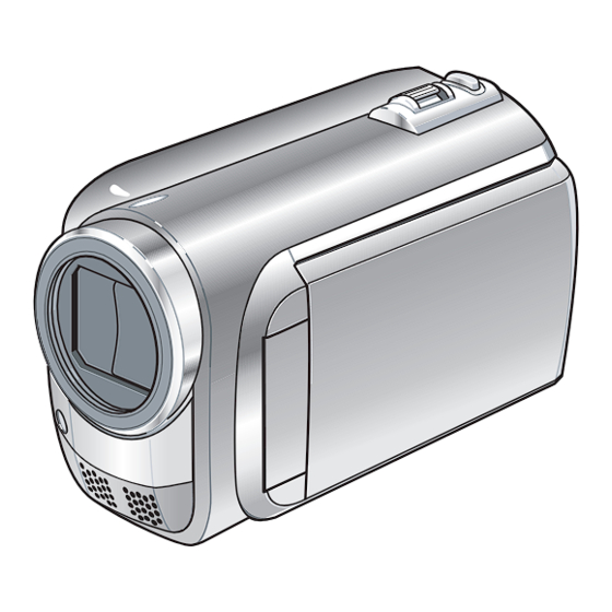
SERVICE MANUAL CAMCORDER YF307<Rev.003> 2009 6 S ERVICE MANUAL GZ-HD300AEK, GZ-HD300AER, GZ-HD300AEU, GZ-HD300AEZ, GZ-HD300BEK, GZ-HD300BER, GZ-HD300BEU, GZ-HD300BEZ, GZ-HD300REK, GZ-HD300RER, GZ-HD300REU, GZ-HD300REZ, GZ-HD320BEK, GZ-HD320BER, GZ-HD320BEU, GZ-HD320BEZ GZ-HD300AEKM,GZ-HD300AERM,GZ-HD300AEUM,GZ-HD300AEZM, GZ-HD300BEKM,GZ-HD300BERM,GZ-HD300BEUM,GZ-HD300BEZM, GZ-HD300REKM,GZ-HD300RERM,GZ-HD300REUM,GZ-HD300REZM, [M9H412] GZ-HD320BEKM,GZ-HD320BERM,GZ-HD320BEUM,GZ-HD320BEZM [M9H416] COPYRIGHT © 2009 Victor Company of Japan, Limited Lead free solder used in the board (material : Sn-Ag-Cu, melting point : 219 Centigrade) TABLE OF CONTENTS PRECAUTIONS . - Page 2 SPECIFICATION General Power supply DC 11 V (Using AC adapter) DC 7.2 V (Using battery pack) Power consumption Approx. 3.5W* * When the LED light is off and the monitor backlight is set to [STANDARD] mode. Dimensions (W × H × D) 53 mm ×...
-
Page 3: Precautions
SECTION 1 PRECAUTIONS SAFETY PRECAUTIONS Prior to shipment from the factory, JVC products are strictly emission. Consequently, when servicing these products, inspected to conform with the recognized product safety and replace the cathode ray tubes and other parts with only the electrical codes of the countries in which they are to be specified parts. - Page 4 1.1.2 Safety Check after Servicing Examine the area surrounding the repaired location for damage (4) Leakage current test or deterioration. Observe that screws, parts and wires have been Confirm specified or lower leakage current between earth returned to original positions, Afterwards, perform the following ground/power cord plug prongs and externally exposed tests and confirm the specified values in order to verify accessible parts (RF terminals, antenna terminals, video...
-
Page 5: Specific Service Instructions
SECTION 2 SPECIFIC SERVICE INSTRUCTIONS DIFFERENCE LIST The following table indicate main different points between models GZ-HD300AEK, GZ-HD300AER, GZ-HD300AEU, GZ-HD300AEZ, GZ-HD300BEK, GZ-HD300BER, GZ-HD300BEU, GZ-HD300BEZ, GZ-HD300REK, GZ-HD300RER, GZ-HD300REU, GZ-HD300REZ, GZ-HD320BEK, GZ-HD320BER, GZ-HD320BEU and GZ-HD320BEZ . MODEL GZ-HD300AEK GZ-HD300AER GZ-HD300AEU GZ-HD300AEZ GZ-HD300BEK GZ-HD300BER GZ-HD300BEU... - Page 6 FIRMWARE UPDATE Connecting Everio to a PC via USB cable enables firmware update. Connect a battery, capable of operating for 10 minutes or longer, and an AC adapter to Everio for update. * The following procedure shows the monitor displays of the firmware update from ver. 0.82 to ver. 1.55. * Use Windows XP or Windows Vista.
- Page 7 (4)Execute the downloaded application software. Fig.2-4-4 (No.YF307<Rev.003>)1-7...
- Page 8 3.Execute update (1)Disconnect the USB cable, and remove Everio from the PC. (2)Check the current and updated versions, and then select "YES". MENU Fig.2-4-5 (3)Carefully read and understand the warning, and then select "YES". * It takes about 1 minutes and 30 seconds to complete the update. MENU MENU Fig.2-4-6...
-
Page 9: Disassembly
SECTION 3 DISASSEMBLY BEFORE ASSEMBLY AND DISASSEMBLY 3.1.1 Precautions 3.1.4 Tools required for disassembly and assembly • Be sure to disconnect the power supply unit prior to mounting Torque driver Tweezers and soldering of parts. YTU94088 YTU94088-003 P-895 • Prior to removing a component part that needs to disconnect its connector(s) and its screw(s), first disconnect the wire(s) from the connector(s), and then remove the screw(s). - Page 10 3.2.2 Assembly/Dissambly of cabinet parts and electrical parts Disassembly procedure NOTE5d: STEP Fig. PART NAME POINT NOTE When connecting the FPC to the connector, insert the FPC straight into the connector. When locking the connector, be B.COVER(N)ASSY 3-2-1 3(S1),2(L1a), 2(L1b) NOTE1 careful not to give so much load that it bends the board.
- Page 11 NOTE21d: When attaching, be careful with the wiring. NOTE21e: During the procedure, be careful not to damage the parts. When attaching the OPE BOARD ASSY with the MONITOR ASSY closed, be especially careful not to break the SWITCH (S401). NOTE22a: When removing the SPEAKER, be careful in handling as the SPACER (SPK) may come off with the SPEAKER.
- Page 12 NOTE4 JACK (S6) COVER (AV) (S6) (S6) (S4a) (S4b) NOTE4 (S4a) (S4b) (S4a) (S4b) (S4a) (S4a) Fig.3-2-4 Fig.3-2-6 NOTE5f (S7) NOTE5a,b (S7) MAIN BOARD ASSY STOPPER NOTE5e NOTE5d NOTE5c RUBBER SPACER Fig.3-2-5 Fig.3-2-7 1-12 (No.YF307<Rev.003>)
- Page 13 CN10a [10] NOTE8 L10b CN10b L10a (S10) (S10) Fig.3-2-8 Fig.3-2-10 (S11) [11] L11b (S9a) (S9b) L11a NOTE9 Fig.3-2-9 Fig.3-2-11 (No.YF307<Rev.003>)1-13...
- Page 14 L14a L14b L14c NOTE14b [10] [14] CN14b(WIRE) CN14a(FPC) L12b WIRE(MIC) L12a FPC(LENS BARR.) (S12) NOTE14a FPC(LENS BARR.) WIRE(MIC) [12] Fig.3-2-12 Fig.3-2-14 NOTE13 (S15) (S13) (S15) [15] GASKET L13b NOTE15 CN15a CN15b L13a GASKET [13] CN13 (S13a) NOTE15 (S13a) MAIN PWB CMOS WIRE GASKET Fig.3-2-13...
- Page 15 NOTE18 (S18b) (S16) (S16) (S18b) WIRE(MIC) [16] [18] L16a NOTE18 WIRE(MIC) L16c L16b (S18a) L19a [19] L19b Fig.3-2-16 Fig.3-2-18 NOTE17b (S20) PLATE(MIC) (S17) (S17) (S17) [20] NOTE20 WIRE(MIC) L20b FRONT COVER ASSY L20a FRME ASSY NOTE17a [17] 0.118N m (1.2kgf cm) Fig.3-2-17 Fig.3-2-19 (No.YF307<Rev.003>)1-15...
- Page 16 NOTE21a (S21b) NOTE21b,d NOTE21e (S21b) SW(S401) CN21b (S21a) WIRE(SPK) [21] L21b CN21b CN21a NOTE21e SW(S401) NOTE21c WIRE(SPK) L21b [21] L21a L21d SW(S408) L21c SW(S408) LEVER [21] KNOB(SLIDE) (S21a) NOTE21a Fig.3-2-20 NOTE22b WIRE(SPK) (S23) (S23) [23] NOTE23 (S22) BKT(SPACER) NOTE22b [22] WIRE(SPK) NOTE22a SPACER(SPK)
- Page 17 3.2.3 Assembly/Disambly of [17] OP BLOCK ASSY/CMOS BOARD ASSY Precautions NOTE17c: (1) Be careful in handling the LENS components. The CMOS BOARD ASSY is included in CMOS Pay special attention to the surfaces to protect them from FRAME ASSY. stains, dust, or scratches. Replace the CMOS BOARD ASSY as a CMOS If the surfaces are soiled with finger prints or other stains, FRAME ASSY, not as a single part replacement.
- Page 18 3.2.4 Disassembly of [23] MONITOR ASSY CAUTIONS (1) During the procedure, be careful in handling the LCD frame of the D. FACE TAPE. Evenly press over the pa- MODULE and other parts. Pay special attention not to per backing of each long / short side of the L shape. damage or stain the monitor screen.
- Page 19 0.118 N m (1.2kgf cm) MONI. COVER (S23a) L23h ASSY L23c L23g L23e HINGE COVER(U) L23a NOTE23p L23f (S23a) (S23a) L23e HINGE UNIT L23d (S23a) NOTE23a L23k HINGE UNIT <NOTE23p,q> ASSY L23n L23j L23m L23p CN23c CN23b NOTE23n MAGNET L23q HINGE UNIT HINGE COVER(L) CN23a...
-
Page 20: Adjustment
SECTION 4 ADJUSTMENT PREPARATION 4.1.3 Tools required for adjustment 4.1.1 Precaution Torque Driver Tweezers YTU94088 YTU94088-003 P-895 Camera system and deck system of this model are specially adjusted by using PC. However, if parts such as the following are replaced, an adjustment is required. - Page 21 • Chip IC Replacement Jig JIG CONNECTOR CABLE CONNECTION To be used for adjustment of the camera system. Connection procedure • Cleaning Cloth NOTE Recommended the Cleaning cloth to wipe down the video • Be sure to turn the power “OFF”, when connecting the JIG heads, mechanism (tape transport system), optical lens sur- CONNECTOR CABLE.
- Page 22 Jig connector diagrams JIG CONNECTOR CABLE (YTU93106D) JIG CONN. BOARD MAIN CN110 (PIN NO.) DSP_TDO DSP_TDO DSP_TCK DSP_TMS DSP_TMS XDSPTRST DSP_TDI REG_2.83V XDSPTRST UATXD0 XDSPSRST IF_TX REG_2.83V UARXD0 OCD_SCL UATXD0 AL_2.8V OCD_SDA IF_TX IF_RX ISSP_DATA SYS_RSTL DSP_RTCK OCD_SCL CAPSENS_DT DSP_TCK DSP_TDI XDSPSRST OCD_SDA...
- Page 23 IDE ADAPTER AND FPC WIRE • IDE ADAPTER and FPC WIRE are used for HDD test. Check with the NOTE, and then refer to the below figure (Fig. 4-3-1, Fig.4-3-2) for the connection procedure. <TYPE-T> FPC WIRE(Parts No.:YTU94165-40) <FRONT SIDE> <BACK SIDE>...
-
Page 24: Trouble Shooting
SECTION 5 TROUBLE SHOOTING SERVICE NOTE 1-24 (No.YF307<Rev.003>) - Page 25 Victor Company of Japan, Limited Camcorder Division 12, 3-chome, Moriya-cho, Kanagawa-ku, Yokohama-city, Kanagawa-prefecture, 221-8528, Japan (No.YF307<Rev.003>) Printed in Japan...