
Related Manuals for Hypertherm powermax1250


Summary of Contents for Hypertherm powermax1250
- Page 1 ® Plasma Arc Cutting System Service Manual 803940 – Revision AMPS...
- Page 2 (P/N 803940) Revision 4 – July 2006 Hypertherm, Inc. Hanover, NH USA www.hypertherm.com © Copyright 2006 Hypertherm, Inc. All Rights Reserved Hypertherm and Powermax are trademarks of Hypertherm, Inc. and may be registered in the United States and/or other countries.
- Page 3 65 6 841 2490 Fax HYPERTHERM BRASIL LTDA. 65 6 841 2489 (Technical Service) Rua Jati, 33 CEP 07180-140 Cumbica Hypertherm (Shanghai) Trading Co., Ltd. Guarulhos, SP - Brasil Unit 1308-09, Careri Building 55 11 6482 1087 Tel 432 West Huai Hai Road...
-
Page 4: Hypertherm Plasma Systems
The size of the surrounding area to be Earthing of Workpiece considered will depend on the structure of Hypertherm's CE-marked equipment is built Where the workpiece is not bonded to earth the building and other activities that are tak- in compliance with standard EN50199. The for electrical safety, nor connected to earth ing place. -
Page 5: Warranty
Hypertherm system. Any damage infringement, and Hypertherm’s obligation to indemnify shall be caused by the use of other than genuine Hypertherm parts may conditioned upon Hypertherm’s sole control of, and the not be covered by the Hypertherm warranty. -
Page 6: Table Of Contents
Le bruit peut provoquer des problèmes auditifs......................1a-5 Pacemakers et prothèses auditives........................1a-5 Un arc plasma peut endommager les tuyaux gelés....................1a-5 Étiquette de sécurité ...............................1a-6 Section 1b SEGURIDAD Reconocimiento de información de seguridad......................1b-2 Siga las instrucciones de seguridad ........................1b-2 powermax1250 Service Manual... - Page 7 Hypertherm IGBT tester ...........................3-9 Indicator LEDS and device tests ........................3-9 IGBT test preparation .............................3-10 IGBT device test using the Hypertherm tester ....................3-10 Troubleshoot the Hypertherm IGBT tester .....................3-11 Schematic for building an IGBT tester......................3-11 IGBT device test using non-Hypertherm tester ....................3-12 Troubleshooting guide ............................3-14...
- Page 8 PARTS – TORCH AND CONSUMABLES T80 hand torch assembly ............................5-2 T80M achine torch assembly ............................5-4 T80 consumable configurations ..........................5-6 T80M consumable configurations ..........................5-7 Recommended spare parts ............................5-8 Section 6 WIRING DIAGRAMS Timing diagrams ...............................6-2 Electrical schematics ..............................6-5 powermax1250 Service Manual...
- Page 9 TABLE OF CONTENTS powermax1250 Service Manual...
-
Page 10: Safety
Compressed Gas Equipment Safety ........................1-5 Gas Cylinders Can Explode If Damaged ........................1-5 Noise Can Damage Hearing .............................1-5 Pacemaker and Hearing Aid Operation ........................1-5 A Plasma Arc Can Damage Frozen Pipes ........................1-5 Additional Safety Information ............................1-5 Warning Label................................1-6 Hypertherm Plasma Systems... -
Page 11: Recognize Safety Information
• Install an aeration manifold on the floor of the water closed container. table to eliminate the possibility of hydrogen • Do not cut containers that have held combustible detonation. Refer to the Appendix section of this materials. manual for aeration manifold details. Hypertherm Plasma Systems 11-98... -
Page 12: Electric Shock Can Kill
• Provide a disconnect switch close to the power grounding conductor first. supply with properly sized fuses. This switch allows • Each Hypertherm plasma system is designed to be the operator to turn off the power supply quickly in used only with specific Hypertherm torches. Do not an emergency situation. -
Page 13: A Plasma Arc Can Cause Injury And Burns
Work Table Connect the work table to an earth power cord ground. Fasten the retaining nut tightly. ground, in accordance with appropriate national or • Tighten all electrical connections to avoid excessive local electrical codes. heating. Hypertherm Plasma Systems 5/6/02... -
Page 14: Compressed Gas Equipment Safety
Protection Association, 470 Atlantic Avenue, Boston, MA 02210 Hazardous Substances, American Welding Society 10. OSHA, Safety and Health Standards, 29FR 1910 550 LeJeune Road, P.O. Box 351040, Miami, FL 33135 U.S. Government Printing Office, Washington, D.C. 20402 Hypertherm Plasma Systems 11-98... -
Page 15: Warning Label
Wear complete body protection. Become trained and read the instructions before working on the machine or cutting. Do not remove or paint over (cover) warning labels. 110391 Rev A Hypertherm Plasma Systems 8-99... -
Page 16: Section 1A
Les bouteilles de gaz comprimé peuvent exploser en cas de dommages .............1a-5 Le bruit peut provoquer des problèmes auditifs......................1a-5 Pacemakers et prothèses auditives ........................1a-5 Un arc plasma peut endommager les tuyaux gelés....................1a-5 Étiquette de sécurité ...............................1a-6 Hypertherm Systèmes plasma 1a-1 2/12/01... -
Page 17: Identifier Les Consignes De Sécurité
• Ne pas couper de récipients contenant des matières Se référer à l’annexe du manuel pour plus de combustibles. renseignements sur les collecteurs d’aération. 1a-2 Hypertherm Systèmes plasma 2/12/01... -
Page 18: Les Chocs Électriques Peuvent Être Fatals
• Installer un sectionneur avec fusibles appropriés, à la prise de terre appropriée. proximité de la source de courant. Ce dispositif permet à • Chaque système plasma Hypertherm est conçu pour être l’opérateur d’arrêter rapidement la source de courant en utilisé uniquement avec des torches Hypertherm cas d’urgence. -
Page 19: L'arc Plasma Peut Provoquer Des Blessures Ou Des Brûlures
Bien serrer l’écrou de retenue. Table de travail Raccorder la table de travail à la terre, • S’assurer que toutes les connexions sont bien serrées conformément aux codes de sécurité locaux ou nationaux pour éviter la surchauffe. appropriés. 1a-4 Hypertherm Systèmes plasma 5/6/02... -
Page 20: Sécurité Des Bouteilles De Gaz Comprimé
LES TUYAUX GELÉS • Se tenir le plus loin possible de la source de courant. Les tuyaux gelés peuvent être endommagés ou éclater si l'on essaie de les dégeler avec une torche plasma. Hypertherm Systèmes plasma 1a-5 2/12/01... -
Page 21: Étiquette De Sécurité
6. Se former à la technique du coupage et lire les instructions avant de manipuler l’équipement ou de procéder au coupage. 7. Ne pas retirer ou peindre (recouvrir) les étiquettes de sécurité. 1a-6 Hypertherm Systèmes plasma 2/12/01... -
Page 22: Seguridad
Los cilindros de gas pueden explotar si están dañados ..................1b-5 El ruido puede deteriorar la audición ........................1b-5 Operación de marcapasos y de audífonos ......................1b-5 Un arco plasma puede dañar tubos congelados ....................1b-5 Etiqueta de advertencia ............................1b-6 HYPERTHERM Sistemas plasma 1b-1 2/12/01... -
Page 23: Reconocimiento De Información De Seguridad
Consulte la sección del apéndice de este • No corte depósitos que hayan contenido materiales manual para conocer detalles acerca del múltiple de combustibles. aireación. 1b-2 HYPERTHERM Sistemas plasma 2/12/01... -
Page 24: El Choque Eléctrico Puede Provocar La Muerte
Prevención ante el electrochoque cortando. Deje la pieza en su lugar o sobre la mesa de Todos los sistemas por plasma de Hypertherm usan alto trabajo con el cable de trabajo conectado en todo voltaje en el proceso de corte (son comunes los voltajes CD momento. -
Page 25: El Arco De Plasma Puede Causar Lesiones Y Quemaduras
Ajuste firmemente la tuerca eléctricos nacionales o locales apropiados. de retención. • Asegúrese de que todas las conexiones eléctricas están firmemente realizadas para evitar sobrecalentamientos. 1b-4 HYPERTHERM Sistemas plasma 4/11/03... -
Page 26: Seguridad De Los Equipos De Gas Comprimido
• Manténgase tan lejos de la fuente de energía como sea posible. Se puede hacer daño a los tubos congelados, o se los puede reventar, si uno trata de descongelarlos con una antorcha por plasma. HYPERTHERM Sistemas plasma 1b-5 2/12/01... -
Page 27: Etiqueta De Advertencia
Proteja su cuerpo 110391 Rev A completamente. 6. Antes de trabajar en la máquina o de proceder a cortar, capacítese y lea las instrucciones completamente. 7. No retire las etiquetas de advertencia ni las cubra con pintura. 1b-6 HYPERTHERM Sistemas plasma 2/12/01... -
Page 28: Specifications
Section 2 SPECIFICATIONS In this section: Power supply ................................2-2 Dimensions and weight ............................2-3 T80 torches ................................2-4 Dimensions ..............................2-5 Symbols and markings .............................2-6 S Mark................................2-6 IEC symbols ..............................2-6 powermax1250 Service Manual... -
Page 29: Power Supply
Drooping *Defined as a plot of output voltage versus output current Rated output current (I 25A – 80A Hypertherm standard rated output 150 VDC voltage (U Duty cycle (X*) at 104°F (40°C) at – Volts AC rms rated conditions (U... -
Page 30: Dimensions And Weight
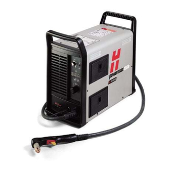
SPECIFICATIONS Dimensions and weight 90 lb (41 kg) 10.5 in (267 mm) 23 in (584 mm) Weight of power supply without torch 19.5 in AM PS (495 mm) powermax1250 Service Manual... -
Page 31: T80 Torches
8.3 pounds (3.8 kg) with 25 ft (7.5 m) lead T80M 9.9 pounds (4.5 kg) with 35 ft (10.7 m) lead 15.0 pounds (6.8 kg) with 50 ft (15 m) lead 21.7 pounds (9.9 kg) with 75 ft (22.5 m) lead powermax1250 Service Manual... -
Page 32: Dimensions
3.9" (99 mm) 2.25" (57 mm) 1.00" (25 mm) T80M machine torch dimensions 1.00" 15.25" (25 mm) (387 mm) 2.03" 8" 1.38" (52mm) (203 mm) (35 mm) 32 pitch 0.125" (3.2 mm) width 0.125" (3.2 mm) height powermax1250 Service Manual... -
Page 33: Symbols And Markings
Plasma torch in the TEST position (cooling and cutting gas exiting nozzle) Plasma torch cutting and gouging Power is AC input power connection Power is The terminal for the external Volt/amp curve, “drooping” protective (earth) conductor characteristic powermax1250 Service Manual... -
Page 34: Maintenance
Hypertherm IGBT tester ...........................3-9 Indicator LEDS and device tests ........................3-9 IGBT test preparation .............................3-10 IGBT device test using the Hypertherm tester ....................3-10 Troubleshoot the Hypertherm IGBT tester .....................3-11 Schematic for building an IGBT tester......................3-11 IGBT device test using a non-Hypertherm tester ...................3-12 Troubleshooting guide ............................3-14... - Page 35 T60M machine torch: connector pinout diagrams and assembly ................3-33 Component replacement ............................3-34 Power cord replacement ..........................3-34 Torch replacement............................3-35 Filter element replacement..........................3-37 Work cable replacement ..........................3-38 Capacitor replacement ...........................3-39 Power board removal and replacement ......................3-40 Heat sink component replacement.........................3-43 powermax1250 Service Manual...
-
Page 36: Controls And Indicators
When illuminated, indicates that a fault condition exists, which prevents system operation. Yellow low line voltage When illuminated, indicates that line voltage is below 170 VAC or above 680 VAC. On CE units, it can also indicate a missing phase. powermax1250 Service Manual... -
Page 37: Theory Of Operation
The control board (PCB3) includes a control switch for the pilot arc, which allows the operator to turn ON the pilot arc (useful when cutting expanded metal), turn OFF the pilot arc (for maximum life of consumables), or to increase the pilot arc to 20A (useful for gouging or non-transferred-arc cutting). powermax1250 Service Manual... -
Page 38: Sequence Of Operation
• Pull the plasma start trigger on the hand torch or the current adjustment knob. press the remote start switch for the machine torch. • The gas solenoid valve (V1) closes. The power circuits are ready. • The gas flow stops. powermax1250 Service Manual... -
Page 39: Troubleshooting Preparation
The complexity of the circuits requires that service technicians have a working knowledge of inverter power supply theory. In addition to being technically qualified, technicians must perform all testing with safety in mind. If questions or problems arise during servicing, call the nearest Hypertherm Technical Services Department listed in the front of this manual. -
Page 40: Internal Inspection
• After the problem has been located and repaired, refer to the Sequence of operation flow diagram in this section to test the power supply for proper operation. powermax1250 Service Manual... -
Page 41: Check Power Switch
The Troubleshooting guide provides most probable causes and solutions. Study the system Note: wiring diagram and understand the theory of operation before troubleshooting. Before purchasing a major replacement component, verify the problem with Hypertherm Technical Service or the nearest Hypertherm repair facility. powermax1250... -
Page 42: Hypertherm Igbt Tester
The Hypertherm IGBT tester requires a minimum of 8V to power its circuitry properly. IGBT test preparation Before testing with the Hypertherm IGBT tester, connect the colored leads to the IGBT as shown on the next page. Note: Before an IGBT can be tested, it must be electrically isolated from all circuits. If the IGBT is installed in a power supply, remove the power board and any lead connections before testing. -
Page 43: Igbt Device Test Using The Hypertherm Tester
Collector 1, (C1) Black lead Emitter 1 (E1) IGBT device test using the Hypertherm tester Using the Hypertherm IGBT tester, press and hold the switch in the desired position to perform each test described in the following table. Switch position... -
Page 44: Troubleshoot The Hypertherm Igbt Tester
MAINTENANCE Troubleshoot the Hypertherm IGBT tester 1. Inspect the leads and the IGBT tester for damage. 2. Verify that the battery voltage is greater than 8V. 3. Test the IGBT Tester, itself, as shown below. If the results do not match the table, replace the lead connections. -
Page 45: Igbt Device Test Using Non-Hypertherm Tester
MAINTENANCE IGBT device test using a non-Hypertherm tester The device tester shown in Schematic for building an IGBT tester has one LED and one pushbutton switch that are used in combination to perform two tests. Note: Before an IGBT can be tested, it must be electrically isolated from all circuits. If the IGBT is installed in a power supply, remove the power board and any lead connections before testing. - Page 46 MAINTENANCE powermax1250 3-13 Service Manual...
-
Page 47: Troubleshooting Guide
MAINTENANCE Troubleshooting Guide powermax1250 3-14 Service Manual... - Page 48 MAINTENANCE powermax1250 3-15 Service Manual...
- Page 49 MAINTENANCE powermax1250 3-16 Service Manual...
- Page 50 MAINTENANCE powermax1250 3-17 Service Manual...
- Page 51 MAINTENANCE powermax1250 3-18 Service Manual...
- Page 52 MAINTENANCE powermax1250 3-19 Service Manual...
-
Page 53: Control Board Leds
START START SIGNAL VALID TRANSFER SELF DIAGNOSTICS FAILURE NORMAL (Blinking at 1 sec rate.) DOWN GOUGE CURRENT INVERTER INTERLOCK (Visible for 10 sec. after event) TORCH STUCK OPEN (Visible for 10 sec. after event) SPARE STATUS powermax1250 3-20 Service Manual... - Page 54 MAINTENANCE powermax1250 3-21 Service Manual...
-
Page 55: Test 1 - Voltage Input
CE unit Black Black (U) White Blue (V) Brown (W) Green Green/Yellow Ground (PE) Input diode bridge Power switch (S1) = Line voltage* = Line voltage = Line voltage* * Single phase Line voltage x 1.414 powermax1250 3-22 Service Manual... -
Page 56: Test 2 - Voltage Balance
Note: Bulk capacitors must be out of circuit. R126 = 20.8k R120 = 21.2k R125 = 21.0k R127 = 21.2k R124 = 24.1k R119 = 24.1k Inverter IGBT (Q6) 750 VDC 375 VDC 375 VDC 375 VDC 375 VDC powermax1250 3-23 Service Manual... -
Page 57: Test 3 - Output Diodes
The diode is shorted if the value is less than 0.1V. Replace the diode. The diode is open if the value is greater than 1.0V in both directions. Replace the diode. Note: In each case, common (black) should be on 3. powermax1250 3-24 Service Manual... -
Page 58: Test 4 - Pilot Arc Igbt (Q8)
• If the values are correct, check the pilot arc IGBT (Q8) with an IGBT tester. If it fails, replace the power board (PCB2) and the pilot arc IGBT (Q8). Gate-drive resistors R108 = 1kΩ R110 = 10kΩ Pilot arc IGBT (Q8) powermax1250 3-25 Service Manual... -
Page 59: Test 5 - Inverter Igbt (Q6) And Pfc Igbt (Q7)
Inverter R82 = 994Ω R87 = 994Ω C100 R83 = 6.1Ω R56 = 4.1Ω C100 R98 = 1Ω R65 = 995Ω R75 = 6.1Ω R84 = 10.4Ω R96 = .4Ω PFC IGBT (Q7) Inverter IGBT (Q6) powermax1250 3-26 Service Manual... -
Page 60: Test 6 - Flyback Circuit
D5 = 24 VDC R2 = 18 VDC D7 = 10 VDC R9 = -6 VDC D9 = 18 VDC R18 = 5 VDC D17 = 5 VDC R20 = 0.75Ω R26 = 18 VDC R55 = 18 VDC powermax1250 3-27 Service Manual... -
Page 61: Test 7 - Torch Stuck Open (Tso)
• Verify that the pilot arc IGBT (Q8) is open by placing a jumper wire between J14 and the pilot arc IGBT (Q8). Then attempt to fire the torch. If the torch fires, replace the pilot arc IGBT (Q8). Note: All values are ±25%. Pilot arc IGBT powermax1250 3-28 Service Manual... -
Page 62: Test 8 - Plasma Start
• With the power OFF, place a jumper wire between pins 3 and 4 of U23. • Turn ON the power. If the torch cap-sensor LED goes out, replace the power board (PCB2). If the LED remains illuminated, replace the control board (PCB3). ETR connector (J18) powermax1250 3-29 Service Manual... -
Page 63: Test 10 - Gas Solenoid
If not, replace the fan. • Check the voltage between the left side of R7 and ground (TP1). If the VDC is zero (0), replace the control board (PCB3). If the value is 5 VDC, replace the power board (PCB2). powermax1250 3-30 Service Manual... -
Page 64: Test 14 - Aux Switch
5 VDC (±0.5V), disconnect the control board and measure for 5 VDC again. If it is still not a constant 5 VDC, replace the power board (PCB2). • If no problems are found while completing the previous steps, replace the control board (PCB3). powermax1250 3-31 Service Manual... - Page 65 Pin 1 Pin 10 violet wire (trigger) White wires (plunger) Red wire (nozzle) Pin 3 Orange wire (cap sense/trigger) Pin 12 blue wire (cap sense) Not used Right handle Left handle Torch body Screws (5) Spring Trigger powermax1250 3-32 Service Manual...
- Page 66 Pin 10 not used White wires (plunger) Pin 3 Orange wire (cap sense) Red wires (nozzle) Pin 12 blue wire (cap sense) Strain relief Strain relief lock Torch Positioning body sleeve Mounting sleeve Screws (3) O-ring powermax1250 3-33 Service Manual...
-
Page 67: Component Replacement
6. Reconnect the electrical power and the gas supply. L1 (U) L2 (V) L3 (W) Ground (PE) Ground (PE) Three-phase Single-phase Standard unit CE unit Standard unit Black Black (U) Black White Blue or Grey (V) White Brown (W) Green Green Green/Yellow powermax1250 3-34 Service Manual... -
Page 68: Torch Replacement
MAINTENANCE Torch replacement Turn OFF (O) the power switch. Unplug the power cord from the power receptacle. Open the Easy Torch Removal (ETR) door and route the lead through the end cap. Door End Cap powermax1250 3-35 Service Manual... - Page 69 Slide the quick-release collar forward to lock in the gas fitting. Verify that the gas fitting is secure. Verify that the red dot on the connector is on top, then plug in the electrical connector. Close the ETR door. powermax1250 3-36...
-
Page 70: Filter Element Replacement
A. Hold the black tab down and slide the filter bowl over the filter element. B. Align the marks on the filter bowl and the filter body. C. Rotate the filter bowl until it locks in place. powermax1250 3-37 Service Manual... -
Page 71: Work Cable Replacement
4. Connect the work cable to the power board at Proper torque is critical. J14.Tighten the nut to 10 in-lb (12 kg cm) of torque. 5. Install the ETR barrier. 6. Install the power supply cover. Connect to J14 Strain relief ETR barrier Work cable powermax1250 3-38 Service Manual... -
Page 72: Capacitor Replacement
Tighten the screws to 20 in-lb (24 kg cm) of torque. 3. Install the power supply cover. Screws for C94 Screws for Remove and install screws from power board side. Remove and install Correct installation capacitors from fan side. powermax1250 3-39 Service Manual... -
Page 73: Power Board Removal And Replacement
5. Disconnect the pilot arc gate drive and the IGBT gate drives from the power board. Then remove the nuts that attach the work lead and power cord ground cable to the power board. Pilot arc gate IGBT gate drives drive (J12) (J6, J7 and J8) Work lead and ground cable attachments powermax1250 3-40 Service Manual... - Page 74 Remove any cables connected at those points. Then remove the retaining screws from the power board. 8. Lift the power board out of the power supply and store it in an anti-static container until you are ready to re-install it. powermax1250 3-41 Service Manual...
- Page 75 3. Reattach the work lead, and power cord ground cable. 4. Re-install the ETR barrier and reconnect the torch lead. 5. Replace the insulation panel and the cover on the power supply. 6. Reconnect the gas supply and the electrical power. powermax1250 3-42 Service Manual...
-
Page 76: Heat Sink Component Replacement
Thermal pad Notes: Apply thermal grease and torque to 8 in-lb (9 kg cm). Apply thermal grease and torque to 20 in-lb (23 kg cm). Apply thermal grease and torque to 35 in-lb (40 kg cm). powermax1250 3-43 Service Manual... - Page 77 MAINTENANCE powermax1250 3-44 Service Manual...
-
Page 78: Parts - Power Supply
Section 4 PARTS – POWER SUPPLY In this section: Exterior ..................................4-2 Interior right side ...............................4-3 Back interior right side ..............................4-4 Interior fan side .................................4-5 Heat sink assembly..............................4-6 Recommended spare parts ............................4-7 powermax1250 Service Manual... -
Page 79: Exterior
128620 Kit: Power supply cover with labels, domestic 128621 Kit: Power supply cover with labels, CE 123645 Work cable with clip, 20 ft (6.1 m) 128629 Kit: Cover screws 128630 Kit: End panel screws 011096 Regulator knob powermax1250 Service Manual... -
Page 80: Interior Right Side
Kit: Gas Manifold with solenoid valve 128628 Kit: ETR Box 046116 Tubing, 8mm OD, 6mm ID, nylon 3 ft. 123602 Gate Drive Cables 128663 Kit: Power board PCB2 108211 On/Off Knob 128662 Kit: Machine Interface 128665 Kit: Strain relief, arc voltage powermax1250 Service Manual... -
Page 81: Back Interior Right Side
Item number Description Designator Qty. 128672 Kit: Power switch 128671 Kit: EMI filter PCB, CE only PCB1 128666 Kit: 8 ft (2.5 m) power cable, domestic 3PH 128667 Kit: 8 ft (2.5 m) power cable, CE 3PH powermax1250 Service Manual... -
Page 82: Interior Fan Side
128627 Kit: Filter 011093 Air filter element 011094 O-ring, NAF3000 filter 011105 O-ring, AF30 filter 228021 Kit: Fan 128680 Kit: Inductor, input choke 128673 Kit: Capacitor C94, C98 128664 Kit: Power transformer 128679 Kit: Inductor, output choke powermax1250 Service Manual... -
Page 83: Heat Sink Assembly
For serial numbers below 1250-014785 or 1250014795 (CE) 128678 Kit: Input diode bridge Kit: Snubber resister (7.5 Ω) 128670 128674 Kit: pilot arc IGBT Snubber resister (20 Ω) 128669 Reference Section 3, Heat sink component replacement , for torque specifications. powermax1250 Service Manual... -
Page 84: Recommended Spare Parts
127128..........Thermal grease, 10 cc T-grease 2500..............4-6 128677..........Kit: Output diode bridge ..................4-6 128676..........Kit: Inverter IGBT ....................4-6 228071..........Kit: PFC IGBT ....................4-6 128675..........Kit: PFC IGBT ....................4-6 For serial numbers below 1250-014785 or 1250-014795 (CE) 128678..........Kit: Input diode bridge..................4-6 128674..........Kit: Pilot arc IGBT .....................4-6 powermax1250 Service Manual... - Page 85 PARTS – POWER SUPPLY powermax1250 Service Manual...
-
Page 86: Parts - Torch And Consumables
Section 5 PARTS – TORCH AND CONSUMABLES In this section: T80 hand torch assembly ............................5-2 T80M machine torch assembly ..........................5-4 T80 consumable configurations ..........................5-6 T80M consumable configurations ..........................5-7 Recommended spare parts ............................5-8 powermax1250 Service Manual... -
Page 87: T80 Hand Torch Assembly
Kit: ETR connector replacement 128642 Kit: T80 start switch replacement * Top assembly includes the following consumables (See T80 consumable configurations for descriptions of consumable parts): 120926 Electrode 120925 Swirl ring 120928 Retaining cap 120929 Shield 120927 Nozzle powermax1250 Service Manual... - Page 88 PARTS – TORCH AND CONSUMABLES 11 12 13 powermax1250 Service Manual...
-
Page 89: T80M Machine Torch Assembly
Kit: ETR Repair 128645 Kit: Torch Mounting (for reassembly after installation) * Top assembly includes the following consumables (See T80M consumable configurations for details of consumable parts): 120926 Electrode 120925 Swirl ring 120928 Retaining cap 120930 Shield 120927 Nozzle powermax1250 Service Manual... - Page 90 PARTS – TORCH AND CONSUMABLES 11 12 13 14 powermax1250 Service Manual...
-
Page 91: T80 Consumable Configurations
Retaining cap Nozzle O-ring 058519 120929 120928 120932 120926 120925 120929 120928 120931 120929 120928 120927 O-ring 058519 220325* 120928 220329 120926 220327 120979 * For use with CE systems. O-ring 058519 60/80A 120926 120925 120928 220059 120977 powermax1250 Service Manual... -
Page 92: T80M Consumable Configurations
Maintain torch-to-work distance of approximately 3/16 inch (4.8 mm). *** Use an ohmic sensing cap when a 220061*** compatible torch height controller is installed. O-ring 058519 120979 120928 220006 120979 120928 220007 120926 120925 120979 120928 120980 powermax1250 Service Manual... -
Page 93: Recommended Spare Parts
Kit: T80/T80M torch cap sensor replacement 128888 Kit: FineCut consumables 128889 Kit: FineCut consumables – CE 087001 T80 hand torch assembly with 25 ft (7.6 m) lead 087004 T80M machine torch assembly 25 ft (7.6 m) lead powermax1250 Service Manual... -
Page 94: Wiring Diagrams
Section 6 WIRING DIAGRAMS In this section: Timing diagrams ...............................6-2 Electrical schematics ..............................6-5 powermax1250 Service Manual... - Page 95 Consumable Re-Seat Pcritical(15) Time Gas Pressure Constant at Torch tdelay (psi) Voltage (volts) 10ms I Setpoint 1.75A/ms (amps) I Work Lead If > 5.0 sec pilot arc time out Digitized XFR signal in DSP and Machine Motion powermax1250 Service Manual...
- Page 96 NOTE: UNIT IS ALREADY IN TRANSFER MODE 3FFh Digitized MUST BE >10ms Must be < 28us Setpoint Setpoint Icommand Reattach Digitized causes XFR signal transfer in DSP If > 5.00 sec CPA timeout I SETPOINT 1.75A/ms I work lead 25A 1.6A 0.4A powermax1250 Service Manual...
- Page 97 WIRING DIAGRAMS powermax1250 Service Manual...
- Page 98 PROPRIETARY AND MAY NOT BE USED FRACTIONS ±1/64 1 OF 1 ANGULAR ±.5∞ FOR MANUFACTURING OR FABRICATION PURPOSES WITHOUT PERMISSION PART MUST BE FREE OF BURRS AND SHARP FROM HYPERTHERM, INC. EDGES. BREAK SHARP EDGES IF NECESSARY WITH CHAMFER OR RADIUS .015 MAX.
Need help?
Do you have a question about the powermax1250 and is the answer not in the manual?
Questions and answers