Table of Contents
Advertisement
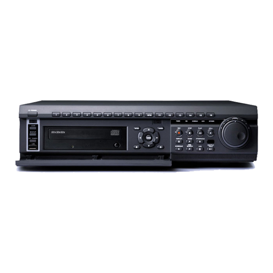
DIGITAL VIDEO RECORDER
USER GUIDE
8/16 CHANNELS
• Thank you for purchasing this Digital Video Recorder.
• Before using the Digital Video Recorder, please ensure that you read and
understand the User Guide.
• Please store the User Guide at an easily accessible location.
• Before connecting and installing any third party cameras, monitors, alarms and
computers, please refer to the appropriate instruction manual for proper operation.
VER M5-3.02
SAFETY PRECAUTIONS
CAUTION:
TO REDUCE THE RISK OF ELECTRIC SHOCK, DO NOT REMOVE COVER (OR BACK).
NO USER SERVICEABLE PARTS INSIDE. REFER SERVICING TO QUALIFIED
SERVICE PERSONNEL.
The lightning flash with arrowhead symbol, within an equilateral
triangle, is intended to alert the user to the presence of un insulated
"dangerous voltage" within the product's enclosure that may be of
sufficient magnitude to constitute a risk of electric shock to persons.
The exclamation point within an equilateral triangle is intended to alert
the user to the presence of important operating and maintenance
(servicing) instructions in the literature accompanying the appliance.
WARNING:
TO PREVENT FIRE OR ELECTRIC SHOCK HAZARD,
DO NOT EXPOSE THIS APPLIANCE TO RAIN OR MOISTURE.
1
DIGITAL VIDEO RECORDER
Advertisement
Table of Contents

Related Manuals for Pinetron DVR-SRX-m5016


Summary of Contents for Pinetron DVR-SRX-m5016
-
Page 1: Safety Precautions
SAFETY PRECAUTIONS DIGITAL VIDEO RECORDER USER GUIDE 8/16 CHANNELS VER M5-3.02 CAUTION: TO REDUCE THE RISK OF ELECTRIC SHOCK, DO NOT REMOVE COVER (OR BACK). NO USER SERVICEABLE PARTS INSIDE. REFER SERVICING TO QUALIFIED SERVICE PERSONNEL. The lightning flash with arrowhead symbol, within an equilateral triangle, is intended to alert the user to the presence of un insulated “dangerous voltage”... -
Page 2: Table Of Contents
Contents ■ Search/Playback …………………………………………………………………………… Time Search ………………………………………………………………………………… Log List Search ……………………………………………………………………………… 52 ■ Safety Precautions ……………………………………………………………………………………… ■ External Search …………………………………………………………………………… ■ Contents ………………………………………………………………………………………………… ■ Back up …………………………………………………………………………… ■ Disclaimer ……………………………………………………………………………………………… Built-in CD RW ……………………………………………………………………………… 54 ■ Warning ………………………………………………………………………………………………… External USB HDD ……………………………………………………………………………... -
Page 3: Disclaimer
Do not use substances containing alcohol, benzene, thinners or other flammable substances to clean or maintain the equipment. The use of these substances may lead to fire. Use a Disclaimer dry cloth on a regular periodic basis and wipe away the dust and dirt that collects on the The information in this manual is believed to be accurate and reliable as of the date of device. -
Page 4: Caution
Caution PACKAGE CONTENTS Do not operate the appliance beyond its specified temperature, humidity or power source ratings. Do not use the appliance in an extreme environment where there is high Please check the package and contents for visible damage. If any components are damaged or temperature or high humidity. -
Page 5: Controls
Do not block the receiver as the remote controller needs the line of sight to Remote control CONTROLS the receiver. signal receiver. [DISPLAY] : Press this button to display the cameras in multi-screen mode Front Panel or to switch sequence function. [ZOOM]: Press this button to display zoom area box;... -
Page 6: Rear Panel Connectors
Remote Controller Rear Panel Connectors DVR ID EXT. SEARCH TIME SEARCH INFORMATION BACK UP DISPLAY MODE PAN/TILT/ZOOM ENTER CANCEL / OSD OFF ZOOM MENU - BUTTON 1) Camera Inputs: BNC input connectors, REWIND + BUTTON 2) 75 Ohm Termination STOP FAST FORWARD 3) ALARM IN/OUT: For connecting alarm inputs (1~16) and alarm out relays (1~4). -
Page 7: Installation & Connections
POWER POWER AC 24V AC 24V INSTALLATION & CONNECTIONS. AWG # 24 Camera, Monitor, Microphone, Alarm sensor and Power cord. 4 ALARM INPUT 1 AUX OUTPUT SPOT MONITOR MAIN MONITOR RS-485 HALF DUPLEX MODE CONTROLLER Tx+Tx- Rx+Rx- J-BOX REAR J-BOX FRONT RS-485 DC 12V DATA2... - Page 8 POWER POWER POWER AC 24V AC 24V AC 24V AWG # 24 VIDEO 4 ALARM INPUT 4 ALARM INPUT 1 AUX OUTPUT 1 AUX OUTPUT Camera 1~16 Camera 17~12( 15) Camera 1~16 Camera 17~12( 15) 1ST MAIN MONITOR SPOT MONITOR 2ND MAIN MONITOR TXB TXA RXB RXA FG ND AC - AC +...
-
Page 9: Pc System Requirement For Network Connection
PTZ connections. QUICK START PAGE PC system requirement for Network connection. The Factory Default password for the unit is “000000” (a) 500MHz CPU (b) 128MB RAM (c) 4MB Video Card (d) Windows 98SE, 2000, ME (e) Spare 10/100-BaseT Ethernet Port (f) RJ-45 Network Cable (g) CAT-5 UTP Cable for LAN (Crossover cable for direct connect to PC) <Disclaimer>... -
Page 10: Live Viewing
LIVE VIEWING Time & Date Setting Display Overview When the DVR is powered on for the very first time, the time and date are set as default to January 1, Recording Mode 2006 Sunday 01:00:00. Before any other operation of the Digital Video Recorder, it is important to setup the time and the date. -
Page 11: Multiscreen Display And Sequencing
Multiscreen Display and Sequencing 3. Quick button for multi screen Display. 1) Press F1 button on the remote controller + <Number> 1. Full Screen Display. Select any camera for Full screen display by pressing the Number button of the For example, press F1 button then number 8. desired camera. -
Page 12: Zooming
Zooming OPERATION During live view mode or playback, it is possible to zoom into a section of the screen to get a Main Menu Overview close-up view of the screen. 1. To activate the digital zoom, select the full screen display of the camera you wish to When the DVR is powered on, Live Viewing screen will appear after initialization about 30sec. -
Page 13: Display Option
Display Option 2. SEQUENTIAL SETUP (Auto Sequence) 1. DISPLAY SETUP ITEM DEFAULT ADJUSTMENT Use Direction buttons [ ] to select “DISPLAY” menu. Then, press [ENTER] button SEQ. 5 Sec Specify the dwell time of each camera or Muliscreen mode is to display “DISPLAY SETUP”. -
Page 14: Camera Setup
Camera Setup 1st Press 2nd Press 3rd Press Use Direction buttons [ ] to select “CAMERA” menu. Then, press [ENTER] button to 10/0 display “CAMERA”. 2. Use Left/Right buttons [ ] or Number button to select the Camera you wish to configure. 3. -
Page 15: Motion Recording
Motion Recording 5. Save changes and exit the menu, press [ENTER] button. Then go “RECORD” Menu. 6. Select “ON” or “OFF” to Enable or Disable motion detection on a per camera, as 1. Use Direction buttons [ ] to select “MOTION” menu. Then, press [ENTER] button to shown below. -
Page 16: Normal Recording
Basic Recording ( Normal Recording) < Approximate File Size> The DVR comes with a certain preset settings from the factory. Therefore once the Quality NTSC UNIT DVR is installed, immediate recording is possible after pressing the record buttons. By 720*480 720*240 360*240 720*576... -
Page 17: Alarm Recording
Alarm Recording 2. ALARM SETUP Please verify the alarm record settings prior to starting alarm recording. Please note that alarm recording is independent of any recording modes. Alarm record starts after Alarm Record Enable. 1. RECORD SETUP Use Direction buttons [ ] to select “ALARM”... - Page 18 <Example 2> 3. ALARM REORD ENABLE Select the usage of the Alarm Record. Mode 1~4 means for Schedule recording Mode 1~4 RECORD Alarm Resulting Actions Normal Motion Normal Press the REC button, then Normal recording starts with High picture quality at 3F/S without Audio. When Alarm is Schedule triggered on this channel, it changed to record with Super picture quality at 15F/S with Audio.
-
Page 19: Schedule Recording
Schedule Recording 5. Enter the beginning and end time, then select Record mode to record. (1) BEGIN: The time of recording start. The schedule chart shows a graphical representation of the defined record mode: Mode1~4. (2) END: The time of recording end. The ending time must not be before the starting However, the schedules are only displayed if a corresponding schedule has been time or the same as the starting time. -
Page 20: Network Setup
Network Setup Summary of combination The static service consists of an IP address that remains constant for the duration of the contract of the internet service, whereas the dynamic service consists of an IP address that RECORD ALARM SCHEDULE RECORD MODE MENU frequently changes every time a new connection is made through the provided modem, or CAMERA USE MOTION... - Page 21 2. E-MAIL <Note> How to connect the DVR via Network in the case of DHCP. The DVR is capable of sending e-mails when an event occurs to up to 5 different e-mail addresses: Alarm with image file, Video Loss, Power Loss (when power recovered), HDD 1.
-
Page 22: System Setup
System Setup 2. TIME 1. GENERAL 1. Use Direction buttons [ ] to select “SYSTEM” menu. Then, press [ENTER] button. 2. Use Left/Right buttons [ ] to select on TAP menu 3. Use Down button [ ] to specify the detail. Use [-, +] button to change the value. - Page 23 3. ACCOUNT 4. DISK Admin can define each user’s Authority. Select User 1~5 , then select Activate option on or off. When enabled, it will be possible to check individually under user settings: Monitoring, Playback, Back up, Network, Configuration (Main Menu Setup), Shutdown (Power off). ITEM ADJUSTMENT Enter the 6 numbers for the new password, and then re-enter the same password under...
-
Page 24: Pan/Tilt Zoom Control
5. INFO PAN/TILT Zoom Control To activate the Pan/Tilt Control, select the full screen display of the camera you wish to control. Then press the [ ] button. Shortcut Menu box pops up, as shown below. P/T/Z/FOCUS <Note > Please Refer to Help Menu for specific control. Press info button on IR remote to display the information. - Page 25 The layout of the PTZ interface conforms to the layout of the front of the DVR or the remote * PTZ Camera Model - PAN/TILT/ZOOM Camera List controller. Menu button is the guide anchor position for all other buttons. When in PTZ interface mode, all buttons used for the PTZ related operation.
-
Page 26: Search/Playback
Right SEARCH/ PLAYBACK HUNT, HTZ-2300 Left Limit Limit HAZEM, RESERVED Time Search Night RVT, EZ Protocol Shot 1. To start playback, press [Time Search] button, Time search Calendar Menu Alarm pops up, as shown below. LG, Dome Protocol Alarm 1 Alarm 2 ELMO, PTC-200C/400C... -
Page 27: Log List Search
Log List Search/ Alarm, Motion Search EXTERNAL SEARCH The logs can be used to search and review directly to a point in time of the recorded data. Alarm, motion, video loss and system related logs can be searched and played back directly This button allows searching for data from the external devices connected through the USB from the time of the incident. -
Page 28: Backup
The progress of the backup will be displayed at the bottom of the window in BACKUP percentages of the entire backup process. Please note that the internal CD-RW Internal CD R/W icon’s color will change to blue to signify that backup is in progress. The OSD will be disappeared by pressing cancel button. -
Page 29: External Usb Hdd
External USB HDD * The CD Playback software will simply “auto-run” and does not require the installation of software on you PC To Read USB backup HDD in Window, please use FAT32 formats. To use bigger size HDD, you need to format in our own methods. Format is discussed in “SYSTEM>DISK”... -
Page 30: Ftp Server
FTP Backup <CF. FAT 32 Formats> 1. Make the partition on external HDD as 32G. FTP back up is activated on “Auto-Backup” Section after setting up FTP server. The Auto (Windows XP will only let you format FAT32 partitions up to 32GB, as MS are trying to backup procedure is the same as using the external USB HDD for backup. -
Page 31: Usb Flash Memory(Snap Shot)
USB Flash Memory (SNAP SHOT) Back up range setup - Current Live or Playback images can be saved as JPEG into Flash Memory stick. Flash Memory Stick is used for Manual backup as well. It is possible to set up backup range automatically on Time Search Menu[by Month, Date, Hour, Minute] 1. -
Page 32: Client Program
CLIENT PROGRAM - Central Management Software DIGITAL VIDEO RECORDER DIGITAL VIDEO RECORDER... -
Page 33: Install
INSTALLATION 2. HOW TO INSTALL (1) Insert “Client Install CD” to CD-ROM of your PC and Find “DvrPlayerinstaller.exe” and 1. PC system requirement double click Minimum Recommended (2) Click 「NEXT」 button below: Windows 98SE, 2000, ME, XP Windows XP Pentium II Celeron 333 Pentium Ⅳ... -
Page 34: Features
FEATURES (6) Double click the ICON to start, enter the password to access. 1. CMS Overview Multiscreen selection Current CMS Mode Time and Date Live /PB mode Switch Quick Button Playback Button Pan/Tilt Control * Enter “0” as the default password. Refer to CMS Setup to change the password. To get rid of this screen, Press “ESC”... - Page 35 (2) Time and Date Display * CMS Setup ① General 1 It shows you current time on LIVE Mode and Playback time on PB mode. a) OSD SETUP Month Date Day of Week Select On-Screen-Display information such as the Time, DVR name, Camera Number, Camera Name, Frame Rates for each camera.
- Page 36 GENERAL 2 ② ④SOUND a) POS Audio alert setting for the CMS. You can toggle to enable the sound or to disable the sound Setting to limit the POS item search. from the software. b). Log Setting to limit the Display of Logs. c).
- Page 37 PAN/TILT Control button. c. Iris Indicator Resulting Actions Iris Open Switch to Full Interface Switch to Compact Interface Iris Close Iris Auto d. Tour Indicator Resulting Actions Set Tour by clicking. Total address is depends on connected Pan/Tilt Camera. Go To, Calls up preset Zoom IN Zoom Out Start Automatic Tour...
- Page 38 HEALTH * Health Report Health Report menu is provided so that users may quickly overview all the condition of Displays the name of the last five DVRs with an problem or event. The color will change connected DVR. You can check maximum 300 DVR statuses such as Failure, Event, Recording appropriately based on the event or problems reported from the DVR.
- Page 39 ** DVR Property ** CMS LOG LIST The Property of DVR can be viewed by Double Click “DVR NO or DVR NAME”. This menu provides CMS log while CMS is operating. For more specific information for each DVR, please refer to DVR Log list. ** DVR LOG LIST This menu provides information such as listed below.
-
Page 40: Dvr Control
DVR CONTROL (3) DEL FROM LIST: Delete selected DVR from CMS List. (4) SETUP: It shows the menu setting of selected DVR. 1. Set List Manager (5) PROPERTY: This menu provides information such as DVR Name, IP number & port, - Set List Manger is mainly used to add or delete DVR on CMS. - Page 41 2. Condition of DVR 3. Indication of Camera The condition of DVR menu is provided so that users may quickly check the condition of each In addition to the Health Status Report and supplementary information from the DVR icons connected DVR. Each Icon means listed below. in DVR window, the Camera Status Bar displays the status of individual cameras.
- Page 42 (3) Multiscreen Display 4. Live Viewing Click the individual Multiscreen buttons to display corresponding multiscreen. Individual DVR monitoring Double click “ “ to display live. (4) Change the camera position. Click on each camera to directly switch the desired camera. (2) On-Screen Indicators There are four types of on screen indicators.
- Page 43 2) Select Search. Remote Search Menu will appear, as shown below. 3) Select desired DVR and Time & Date for Playback. To begin playback, click “Play” button. (See “Playback” section). 4) Selected camera begins playback during live viewing. Motion Recording Playback Live viewing Playback...
- Page 44 (2) There are four types of Context Menu on playback during Live viewing. Click Right Mouse 5. Context Menu Button to display Context Menu. The context menu allows access to the submenus for the channel, DVR and the Virtual DVR. The submenus allow access to various features for each individual submenu type.
- Page 45 1) Remote Playback 6. Playback Remote Playback is provided so that users directly playback the stored video on the DVRs that have been added onto the DVR window using the DVR Set List Manager can be accessed internal HDD through CMS. in Playback Mode for remote playback or to download the files onto the remote PC.
- Page 46 Remote Download Download Complete: Current time will be changed to message Remote Download is provided so that users save on remotely connected computer “ Download Complete” after the download has been completed, as through CMS. shown below. ① Select button and desired DVR. Click ②...
- Page 47 7. DVR Menu Setup 2) Sequential Mode DVR Menu Setup allows modification of various system settings to the DVR through CMS as it would be done on the DVR by accessing it’s menu. a. Sequential Interval: 1~30 sec. Select any DVR for Menu setup. Context Menu will appear on screen by Right- clicking. b.
- Page 48 Motion Record Set up Alarm Record 1) Alarm Record Set up ⓐ Record Time : Adjust Post-Event Duration. ⓑ Camera : Select camera for ⓐ ⓒ Motion Level Adjust Motion ⓐ Select Enable or Disable to Record. ⓑ Sensitivity (1~20) ⓐ...
- Page 49 3) Alarm Record Enable The detailed Menu pops up for selected Day, as shown below. Enter the beginning and end time, and then select Record Mode to record. Save setup and exit the menu select “OK”, or otherwise exit the menu without making changes select “Cancel”.
- Page 50 (7) Network Set up (8) System Setup 1) General ⓐ ⓑ ⓒ ⓓ ⓔ Select Bandwidth limit or blocking options. a. System ID : Configure Set ID. b. Auto Key Lock: ON/OFF ⓐ c. Key Tone: Key tone ON/OFF d. Select overwrite HDD. e.
- Page 51 5) FTP Server Set up 3) Password Changed the user Password up to 5 users. 4) Control Set up the FTP Server for Auto Back up. Refer to FTP Back up. ⓐ ⓑ ⓒ d. Stop Recording e. Schedule On/Off Alarm Activated through Network DIGITAL VIDEO RECORDER DIGITAL VIDEO RECORDER...
-
Page 52: Virtual Dvr
(1) ADD to CMS List VIRTUAL DVR Please follow steps to Make Virtual DVR. 1) NAME: Enter Virtual DVR title to display on CMS window. 1. What is Virtual DVR. Virtual DVR is not an actual DVR, but a combination , or group of several DVRs already listed * Auto Arrange : under the DVR window. - Page 53 2) Any selected camera on DVR. 3. Editing Virtual DVR ① Click any DVR on DVR Window while Virtual DVR is activating. Double click the desired Virtual DVR . ② After camera Icons diplyed, any camera on DVR to directly drag the desired channel. In the following exampels, Camera No 1 on 3 DVR is draged to Channel No 14.
- Page 54 3. Double click “Make New Connection”. Appendix: How to connect modem Please follow the next procedure after installed client software. We provide client software in a CD. 1. Connect modem to the back of DVR RS-232C.(MODEM) 4. Click “Next” at the window of network connection wizard. 2.
- Page 55 5. Check “Dial-up to private network” and click “Next”. 7. Check “For all user” and click “Next” 6. Enter the telephone number, which is connected, to the DVR 8. Type DVR at the parameter, check “Add a shortcut to my desktop” and click “Finish”...
- Page 56 11. Open CMS and click Set list manager 9. Type “admin or user1~5” at the user name and enter the password (Six digits 000000 are initial password) click “Dial” 10. You can find this window if connection is succeed and see the speed of this 12.
-
Page 57: Web Cms
13. You will see the picture if connected successfully. Appendix 2: WEB CMS Web CMS is a CMS software that run over Internet Explorer. It is extremely convenient since the user does not need to install dedicated CMS software in the PC. The function is exactly same as CMS except that WEB CMS does not support Download. - Page 58 Click on Web CMS(Use overlay) to connect to Click Security Tab the DVR. Please refer to page 85 for more Click on Custom Level information on CMS overlay. A small icon will appear on the upper left corner of the internet explorer indicating the Click Enable for to Download unsigned ActiveX user for the presence of Active X.
-
Page 59: View Only
APPENDIX 4: AVI Converting When the Image Loading is done, the WEB CMS version should appear along with the images from Required Software for PC the DVR. Avi Player Divx 4.0 Video Codec It is used for only MPEG4 DVR CMS file and back-up file. How to change CMS file to AVI file. -
Page 60: Specification
Specifications 16CH 16CH PRO Choose Output file.(Otherwise it is saved as same name avi file) 4. Select FOURCC Video, Resolution, Video Channel, Audio Channel. Video Input/ Loop Out 8 (NTSC/PAL) 16 (NTSC/PAL) 16 (NTSC/PAL) (This is automatically displayed). Video Output Monitor, S-Video, VGA, SPOT-OUT Click “... - Page 61 General Power AC 100~240V( Universal) , 50/60 Hz Power Consumption 82Watt Operation Temperature 0℃~40℃ Dimension / Weight 430(W) x 450(D) x 100(H) 8.7 Kg Revised at Mar2007 DIGITAL VIDEO RECORDER...
Need help?
Do you have a question about the DVR-SRX-m5016 and is the answer not in the manual?
Questions and answers