Table of Contents
Advertisement
Quick Links
Advertisement
Table of Contents

Related Manuals for Avidyne DFC90

Summary of Contents for Avidyne DFC90
- Page 3 Page Chg Page Chg Page Chg Cover…...0 3-2……….3 5-8……….3 Page #..3 3-3……….3 5-9……….2 TOC-1..3 3-4……….3 5-10……..2 TOC-2…..3 3-5……….3 5-11……..3 1-1………2 3-6……….3 5-12……..3 1-2……….3 3-7……….0 5-13……..2 1-3……….3 3-8……….3 5-14……..2 1-4……..3 3-9……….0 5-15……..2 1-5……..3 3-10……..0 5-16……..3 1-6…….…3 3-11……..0 5-17……..3 1-7…….…3 3-12……..2 5-18……..3 1-8…….…3 4-1……….2 5-19……..3...
-
Page 4: Table Of Contents
DFC90 Digital Autopilot | PILOT GUIDE TABLE OF CONTENTS System Overview ..............1-2 FUNCTIONAL OVERVIEW ............1-3 GENERAL AUTOPILOT OPERATIONS ........1-4 Always a vertical and lateral mode engaged ......... 1-4 Single press to hold, Dual button press to capture ........ 1-4 Primary location for bug/target setting ........... 1-5 Aural Alerts ................... - Page 5 Loss of Turn Coordinator ..............5-6 Loss of AHRS (Single PFD Equipped Aircraft) ........5-7 Loss of AHRS (Dual Avidyne PFD Equipped Aircraft) ......5-7 Loss of Air Data ..................5-8 Total Loss of PFD (Single PFD Equipped Aircraft) ........ 5-9 Total Loss of PFD (Dual PFD Equipped Aircraft) ........
-
Page 7: System Overview
System Overview ..............1-2 FUNCTIONAL OVERVIEW ............1-3 GENERAL AUTOPILOT OPERATIONS ........1-4 Always a vertical and lateral mode engaged ......... 1-4 Single press to hold, Dual button press to capture ........ 1-4 Primary location for bug/target setting ........... 1-5 Aural Alerts ................... 1-5 Armed vs Engaged modes indications .......... -
Page 8: System Overview
Note: For those aircraft that are not equipped with a 430-family GPS Nav-Com, the Aspen PFD converts the signals such that the DFC90 should behave in accordance with these descriptions. If the GPS or NAV does not support an input, the Aspen PFD sends the input as invalid to the DFC90. -
Page 9: Functional Overview
FUNCTIONAL OVERVIEW The Avidyne DFC90 autopilot supports the following functions: Flight Director Heading Capture/Hold NAV Tracking GPSS Mode Approach Mode (includes LOC, ILS, VOR, BC, LPV, LNAV/VNAV, LNAV+V) Altitude Hold Altitude Capture Vertical Speed Hold Indicated Airspeed Mode Straight and Level Speed-based Envelope Protection (EP™) -
Page 10: General Autopilot Operations
ALWAYS A VERTICAL AND LATERAL MODE ENGAGED The DFC90 autopilot has been designed to always have both a lateral and vertical mode engaged. If a specific lateral mode has not been selected by the pilot, then the system defaults to Roll Hold mode. -
Page 11: Primary Location For Bug/Target Setting
The primary location for setting the HDG and ALT targets are via line select keys and right-hand knob on the Avidyne PFD or the right-hand knob on the Aspen PFD. VS target can optionally be set via a line select key and right- hand knob on the Avidyne or Aspen PFD. -
Page 12: Armed Vs Engaged Modes Indications
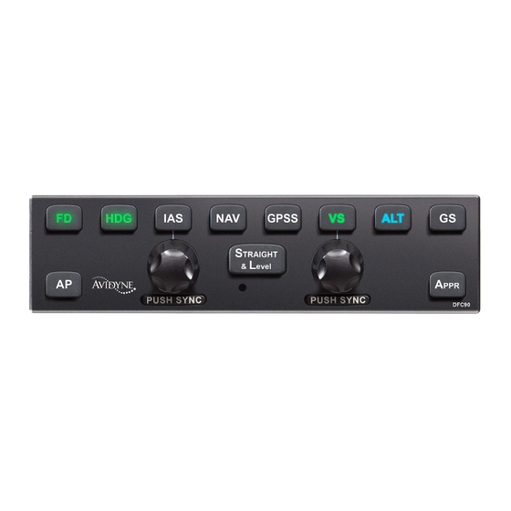
PFD mode annunciator strip. The images below (Avidyne on top and Aspen in the middle) demonstrate the armed and engaged coloring on both the displays and the autopilot control head. In this example, Heading (HDG) and Pitch modes are engaged and Nav mode is armed. -
Page 13: Mode Transition Indication
(trim will not adjust and the AP will not disengage). For predictability of results, pilots of DFC90-equipped aircraft should therefore determine whether the aircraft is equipped with a pitch servo or pitch trim and the resulting behavior before actuating the trim switch in IMC conditions. -
Page 14: Envelope Protection
ENVELOPE PROTECTION (EP™) The DFC90 system provides speed-based Envelope Protection (EP™) (underspeed and overspeed warnings and protection) when in any coupled autopilot mode. NOTE No Envelope Protection in Flight Director Mode Envelope Protection (EP™) is not provided during flight director-only (non-coupled) operations. - Page 15 PFD, a “SPEED PROTECTION ACTIVE” aural alert in the headsets, and by a flashing of any engaged (green) autopilot mode annunciators. The DFC90 is capable of taking flap position into account in Envelope Protection (EP™) and Envelope Alerting (EA™) calculations and as a result, the definition of V...
-
Page 16: Full-Time Envelope Alerting
The DFC90 autopilot provides speed-based and attitude-based envelope alerting when the autopilot is not engaged (servos not coupled). [Requires Avidyne PFD Rel 8.0.4 or Aspen PFD v2.6 and DFC90 Rel 2 or later.] Full-time Envelope Alerting (EA™) is triggered when the DFC90... - Page 17 NOTE Suppression of Full-time Envelope Alerting Full-time Envelope Alerting (EA™) is suppressed during very low power (near idle) conditions when flaps are set to the full-flap position in order to minimize nuisance calls in the landing phase. Full- time Envelope Alerting (EA™) is also suppressed anytime Indicated Airspeed is less than 50 KIAS.
- Page 18 bars present and no autopilot mode annunciators aside from the “AP READY” one along the top edge of the PFD. If an underspeed condition is recognized, an “UNDERSPEED” text alert is displayed on the PFD and a “CAUTION, UNDERSPEED” aural alert is played in the headsets and is repeated approximately every 6 seconds until the condition is no longer valid.
-
Page 19: Baro Adjust
To disable Full-time Envelope Alerting (EA™), pull the autopilot circuit breaker. (* In cases of pre-Rel 8.0.4 Avidyne PFD code combined with post-Rel 2 DFC90 code, the active (green) autopilot mode annunciators will flash during Underspeed conditions. This is a normal consequence of maintaining backward compatibility.) -
Page 20: Engagement And Hold Limits
ENGAGEMENT AND HOLD LIMITS The DFC90 has maximum engagement limits beyond which the autopilot may not allow a mode to be selected, and maximum hold limits for various parameters. The engagement limits of the autopilot are wider than the hold limits. If the autopilot is engaged... -
Page 21: Comparators
COMPARATORS The DFC90 autopilot is always running comparators in the background. There are several types of comparators running during operation of the autopilot as noted in the chart below. If conflicting information is provided, the comparator identifying the conflict with the accompanying pilot indication and autopilot... -
Page 22: Autopilot Engagement
AUTOPILOT ENGAGEMENT From a standby state (autopilot has power, “AP READY” displayed but no modes are engaged and the airplane is within the engagement limits defined above), pressing any button on the autopilot will engage the DFC autopilot. If a specific lateral and/or vertical mode is not pressed, the system will default to ROLL hold mode in the lateral channel and PITCH hold mode in the vertical channel. -
Page 23: Fd Vs. Ap
Press the “AP” button on the autopilot control panel (servos will disconnect but the flight director will remain active); Pull the circuit breaker(s) controlling the power to the autopilot. For those aircraft with the stall warning wired directly to the autopilot, the autopilot will also disconnect if the stall warning alarm is present in the aircraft. -
Page 24: Dual Pfd Operations
PFD-PFD comparator. If manually transitioning from an Altitude Capture to Altitude Hold mode in dual-PFD equipped aircraft, it may be necessary to press the ALT button on the DFC90 control panel a second time in pre- Release 8.0.6 systems. Change 3... -
Page 25: Pfd Annunciations
(green) autopilot mode annunciators will flash. The tables below are a listing of all annunciations that are possible with the DFC90 system. DFC90 Annunciations Note: In Aspen PFD equipped aircraft, “AP READY” is shortened to “AP RDY”. -
Page 27: Normal Startup Sequence
Normal Startup Sequence ..........2-2 POWER CONSIDERATIONS ............2-2 SELF-TEST/ALIGNMENT ............2-2 BRIGHTNESS CONTROLS ............2-2 PRE-FLIGHT TEST ..............2-3 BEFORE TAKEOFF TECHNIQUES ..........2-4 Normal Startup Sequence... -
Page 28: Normal Startup Sequence
2 Normal Startup Sequence POWER CONSIDERATIONS The DFC90 consumes 0.25A when no servos are in operation and up to 0.9A with all servos operating at 100% duty cycle. There is no on/off switch to the DFC-series of autopilots. As soon as the governing power bus is active through normal aircraft checklist steps, the autopilot will power up. -
Page 29: Pre-Flight Test
PRE-FLIGHT TEST 1. Ensure “AP READY” is displayed on PFD annunciator strip 2. Press AP button on autopilot control head a. Ensure AP button is lit in green b. Ensure “AP”, “ROLL”, “PITCH” annunciations are depicted in green on the PFD annunciator strip 3. -
Page 30: Before Takeoff Techniques
NOTE Preflight Test Does Not Test Every Aspect of AP The Pre-Flight test of the DFC90 autopilot outlined above will check the functionality of such items as the ability of the autopilot to engage and disconnect, the ability of the autopilot to engage the roll axis control surfaces, and the communications between the autopilot and the PFD. - Page 31 Climb-out/Enroute .............3-2 NORMAL OPERATING MODES ..........3-2 Pitch Mode .................... 3-2 Roll Mode ..................... 3-2 Heading (HDG) Mode ................3-3 Navigation (NAV) Mode ................ 3-3 GPS Roll Steering (GPSS) Mode ............3-4 Altitude Hold (ALT) Mode ..............3-5 Indicated Airspeed (IAS) Hold Mode ............. 3-5 Vertical Speed (VS) Hold Mode ............
-
Page 32: Climb-Out/Enroute
3 Climb-out/Enroute This section covers normal modes of the autopilot during climb- out and enroute operations as well as procedures, mode control and display. NORMAL OPERATING MODES Envelope Protection (EP™) is active in all of the autopilot modes defined below. PITCH MODE In Pitch Hold mode, the autopilot will maintain a constant pitch from the moment of mode entry. -
Page 33: Heading (Hdg) Mode
Primary Nav line select key (LSK) on the Avidyne PFD or the CDI Navigation Source Select button along the bottom edge of the Aspen PFD. This could be GPS or it could be VLOC. -
Page 34: Gps Roll Steering (Gpss) Mode
to a wind-corrected heading until the station signal is re-acquired and signal tracking can resume. For the condition when Nav mode is conducting its own 45 degree intercept, this is depicted by a cyan “NAV” autopilot mode annunciator indicating Nav mode is armed, followed by a green “45 INT”... -
Page 35: Altitude Hold (Alt) Mode
The system will light up the control panel button in green, sync the altitude bug on the altimeter to the nearest 10 feet to current altitude (Avidyne PFD) or current altitude (Aspen PFD) and turn it solid, and hold the altitude at the time of mode entry. -
Page 36: Vertical Speed (Vs) Hold Mode
VS to the closest 50 fpm to the current aircraft VS. A secondary method is via a LSK on the Avidyne or a combination of a LSK and right hand knob on the Aspen PFD. - Page 37 NOTE Logical Combination of Commanded Targets A logical combination of commanded autopilot targets means a combination of the altitude bug and either the vertical speed bug or indicated airspeed bug that can be achieved. For example, an altitude bug that is above current aircraft altitude and a positive vertical speed bug is a logical combination.
- Page 38 ‘thousands’ mode, ‘hundreds’ mode, and ‘tens’ mode with each press of the adjacent line select key. Setting the Altitude Bug in DFC90 (Avidyne PFD-equipped aircraft) There is also a ‘black out’ period where the autopilot will ignore the commanded target altitude if it is being edited as the original target altitude is approached.
-
Page 39: Straight And Level
STRAIGHT AND LEVEL NOTE Straight and Level Definition Pressing the “STRAIGHT AND LEVEL” button on the autopilot will result in a zero bank, +2 pitch angle attitude. It is not an altitude hold mode or a zero vertical speed mode, nor does it hold a heading. -
Page 40: Pilot Selectable Intercepts
Straight and Level mode can be entered from any autopilot state, including from the off position. NOTE Limitation of Overspeed Protection in Straight and Level Overspeed protection is not ensured during initiation of Straight and Level mode. Depending on the dynamics of the airplane and the available torque in the servos, the recovery to straight and level conditions may exceed V... - Page 41 The heading knob can be adjusted at any time (before or after entering pilot selectable intercept mode) and the system will adjust the intercept angle accordingly. The desired means of mode entry is via a simultaneous push of both the heading (HDG) and lateral nav (GPSS or NAV) buttons on the autopilot control panel.
-
Page 42: Control Wheel Steering Mode
CONTROL WHEEL STEERING MODE Control Wheel Steering (CWS) mode is entered by pressing the CWS button on the aircraft yoke in those aircraft that support this functionality. CWS mode allows the servos to be temporarily disengaged for the duration that the CWS button is held down, providing an opportunity for the pilot to manually maneuver the aircraft as desired without disconnecting the autopilot. - Page 43 Approach Procedures ............4-2 GENERAL BEHAVIOR ..............4-2 APPROACH MODES ..............4-2 WAAS Approaches ................4-2 GPS approach (RNAV or Overlay or LNAV) .......... 4-5 VOR approach ..................4-5 Localizer approach ................4-6 ILS approach including glide slope intercept ......... 4-7 Procedure Turn ILS or Localizers ............4-8 Back course approaches ..............
-
Page 44: Approach Procedures
Note: For those aircraft that are not equipped with a 430-family GPS Nav-Com, the Aspen PFD converts the signals such that the DFC90 should behave in accordance with these descriptions. If the GPS or NAV does not support an input, the Aspen PFD sends the input as invalid to the DFC90. - Page 45 WAAS approaches are intended to flown in NAV APPR mode in the DFC90 system and thus the “Primary Nav” LSK must be set to GPS1/2. Roll commands are issued by the GPS Nav-Com in GPSS mode instead of the DFC90 and proper vertical guidance cannot be assured, hence the need to fly WAAS approaches in NAV APPR modes.
- Page 46 must be pressed. If it is not manually changed to NAV, then an automatic switch will occur when/if a GPS glide slope signal is received. In either the manual or automatic case, the AP switches to NAV APPR. Then fly coupled to MDA. If a level off at the MDA is desired, the ALT button must be pressed on the autopilot.
-
Page 47: Non-Waas Gps Approach (Rnav Or Overlay Or Lnav)
NON-WAAS GPS APPROACH (RNAV OR OVERLAY OR LNAV) □ Ensure the Primary Nav LSK is set to a GPS source and a GPS approach is loaded in the GPS Nav-Com □ Press the “NAV” or “APPR” or “GPSS” buttons on the autopilot control panel Note that the “NAV”... -
Page 48: Localizer Approach
GPS Nav-Com navigator, ensure the correct navigator is selected in the PFD Primary Nav LSK, and ensure the DFC90 is in NAV mode. When flying a Vectors-To-Final approach, use the Heading knob and the “HDG” button on the autopilot control panel when ATC is issuing vectors. -
Page 49: Ils Approach Including Glide Slope Intercept
ILS APPROACH INCLUDING GLIDE SLOPE INTERCEPT When flying a Vectors-To-Final approach, use the Heading knob and the “HDG” button on the autopilot control panel when ATC is issuing vectors. NAV APPR can be armed prior to capturing the localizer beam but it is highly recommended to wait until ATC clears you for the approach before arming NAV and APPR. - Page 50 2. The selected GPS Nav-Com (VLOC1 or VLOC2) has a valid localizer/glide slope frequency loaded in the active; 3. NAV mode on the DFC90 must be armed (cyan) or engaged (green). (APPR mode will also be automatically armed or engaged under these conditions);...
-
Page 51: Procedure Turn Ils Or Localizers
NAV APPR modes by simultaneously pressing the “HDG” button and the “NAV” or “APPR” button. If equipped with a combined DFC90/GNS430W (or GTN) set of equipment and if the procedure turn is activated in the GPS Nav- Com, then the autopilot can be flown in GPSS mode by pressing the “GPSS”... -
Page 52: Back Course Approaches
VHF receiver is locked onto a valid signal and there is a sufficient difference between aircraft heading and the selected course. There is no “REV” or similar button in a DFC90 autopilot. A “BC” annunciation will be added to the HDI (LDI in an Aspen), the HDI (or LDI) and CDI indicators will display correct sensing, and the autopilot will turn in the proper direction. - Page 53 Loss of Turn Coordinator ..............5-6 Loss of AHRS (Single PFD Equipped Aircraft) ........5-7 Loss of AHRS (Dual Avidyne PFD Equipped Aircraft) ......5-7 Loss of Air Data ..................5-8 Total Loss of PFD (Single PFD Equipped Aircraft) ........ 5-9 Total Loss of PFD (Dual PFD Equipped Aircraft) ........
-
Page 54: Abnormal Procedures
“GS” button on the autopilot control panel multiple times will produce a series of events in the data log that will aid the Avidyne Service Center in finding and analyzing the data logs during troubleshooting operations. -
Page 55: Loss Of Pfd Display (Ahrs Still Operational)
LOSS OF PFD DISPLAY (AHRS STILL OPERATIONAL) Failure Indication: A loss of PFD display condition is identified by a display being unreadable but PFD bezel button lights are still lit. Functionality Lost: Under these conditions, if there are no readable PFD displays left, there is a degradation in the ability to enter some autopilot commands/bug settings. -
Page 56: Loss Of Pfd Bezel Buttons And Knobs
Use the autopilot in the remaining usable modes (e.g. Alt Hold, NAV, GPSS, VS, IAS, Envelope Protection). Consider pulling both PFD circuit breakers for less than 20 seconds to conduct a warmstart (if Avidyne PFD equipped). Change 3 Abnormal Procedures... -
Page 57: Loss Of Pfd Display And Bezel Buttons
Use the autopilot in the remaining usable modes (e.g. Alt Hold, NAV, GPSS, VS, IAS, Envelope Protection (EP™)). Consider pulling both PFD circuit breakers for less than 20 seconds to conduct a warmstart (if Avidyne PFD equipped). Abnormal Procedures Change 3... -
Page 58: Loss Of Turn Coordinator
LOSS OF TURN COORDINATOR In Cirrus SR2X or Piper PA46 installations where the DFC90 is replacing a STec 55X autopilot, the DFC90 will use the previously installed turn coordinator as a source of attitude comparison. In all other cases, there is no connectivity to a turn coordinator and this scenario does not apply. -
Page 59: Loss Of Ahrs (Single Pfd Equipped Aircraft)
Immediately transition to hand-flying via the standby instruments and seek VMC as soon as feasible. Consider attempting a single PFD warmstart by cycling both PFD circuit breakers for less than 20 seconds (if Avidyne PFD equipped). LOSS OF AHRS (DUAL AVIDYNE PFD EQUIPPED AIRCRAFT) -
Page 60: Loss Of Air Data
LOSS OF AIR DATA This scenario is only applicable to Avidyne PFD-equipped aircraft. Failure Indication: A failure of the on-board air data system(s) is indicated by the airspeed, altimeter and vertical speed tapes being replaced by Red-Xs. Functionality Lost: The following autopilot modes will be lost: □... -
Page 61: Total Loss Of Pfd (Single Pfd Equipped Aircraft)
TOTAL LOSS OF PFD (SINGLE PFD EQUIPPED AIRCRAFT) Failure Indication: A total failure of the PFD is indicated by both the display and bezel buttons all blank/unlit. Functionality Lost: A loss of the PFD will result in a complete loss of autopilot functionality. -
Page 62: Loss Of Engine
LOSS OF ENGINE Loss of engine does not affect the DFC90 operation but the DFC90 autopilot can be useful during loss of engine situations. One technique is to set the IAS bug to best glide speed and engage IAS mode in the event of engine-out conditions. The... -
Page 63: Other Error Modes
Autopilot failures that prevent any operation are annunciated across the center of the PFD mode annunciator strip in amber (yellow) as shown in the examples immediately below. PFD Autopilot Annunciator (Avidyne top image, Aspen bottom image) GENERAL OR UNKNOWN FAILURES Failure Indication:... -
Page 64: Ahrs-Tc Miscompare During Ground Operations
AHRS-TC MISCOMPARE DURING GROUND OPERATIONS In Cirrus SR2X or Piper PA46 installations where the DFC90 is replacing a STec 55X autopilot, the DFC90 will use the previously installed turn coordinator as a source of attitude comparison. In all other cases, there is no connectivity to a turn coordinator and this scenario does not apply. -
Page 65: Built-In Test (Bit) Failure
BUILT-IN TEST (BIT) FAILURE Failure Indication: If the DFC-PFD system recognizes that the autopilot is invalid due to failing an internal self-test, a yellow “AUTOPILOT INOP FAIL” message is displayed along middle of the PFD SELF TEST annunciator strip. Functionality Lost: All autopilot functionality will be lost for the duration of this message display. -
Page 66: Ahrs Aligning
AHRS ALIGNING Failure Indication: If the PFD AHRS has not finishing aligning, a yellow “AUTOPILOT INOP AHRS ALIGNING” message is displayed along the middle of the PFD annunciator strip. This message should be expected to be seen during all normal ground operations in the course of all standard alignments. -
Page 67: No Communication With Autopilot
NO COMMUNICATION WITH AUTOPILOT Failure Indication: If the PFD stops receiving data from the autopilot, a yellow “NO AUTOPILOT” message is displayed in COMMUNICATION WITH the center of the PFD annunciator strip. Functionality Lost: All autopilot functionality will be lost for the duration of this message display. -
Page 68: Trimming Up/Down
TRIMMING UP/DOWN Failure Indication: If the DFC-PFD system recognizes that trim has been running for an excessive duration, a yellow “TRIMMING UP” or “TRIMMING DN” message is displayed on the PFD. Functionality Lost: No functionality has been lost. In all cases, the trim system can be manually overridden with pilot-controlled control stick/yoke inputs. -
Page 69: Gpss Invalid
GPSS INVALID Failure Indication: If the DFC-PFD system recognizes that the autopilot mode is GPSS but the roll steering information from the GPS Nav-Com is invalid, a yellow “GPSS INVALID” message is displayed on the PFD. Functionality Lost: Either a flight plan has not been entered in the governing GPS Nav-Com and GPSS mode was selected on the autopilot control head in which case, there is no lost of functionality, or the system is unable to fly the flight plan in GPSS roll steering due to some... -
Page 70: Nav Invalid
NAV INVALID Failure Indication: If the DFC-PFD system recognizes that the VHF lateral nav signal from the GPS Nav-Com is invalid, a yellow “NAV INVALID” message is displayed on the PFD. In addition, the Horizontal Deviation Indicator (HDI)/Lateral Deviation Indicator (LDI) along the bottom edge of the ADI will be Red-X’d. -
Page 71: Glide Slope Invalid
GLIDE SLOPE INVALID Failure Indication: If the DFC-PFD system recognizes that the VHF vertical nav signal (glide slope) from the GPS Nav-Com is invalid, a yellow “GS INVALID” message is displayed on the PFD. In addition, the Vertical Deviation Indicator (VDI) along the right edge of the ADI will be Red-X’d. -
Page 72: Tc Fail
TC FAIL In Cirrus SR2X or Piper PA46 installations where the DFC90 is replacing a STec 55X autopilot, the DFC90 will use the previously installed turn coordinator as a source of attitude comparison. In all other cases, there is no connectivity to a turn coordinator and this scenario does not apply. -
Page 73: Ahrs Miscomp
AHRS MISCOMP In Cirrus SR2X or Piper PA46 installations where the DFC90 is replacing a STec 55X autopilot, the DFC90 will use the previously installed turn coordinator as a source of attitude comparison. In all other cases, there is no connectivity to a turn coordinator and this scenario does not apply. -
Page 74: No Pfd Comm
All autopilot functionality will be lost. Recommended Pilot Action: Immediately transition to hand-flying the aircraft. Consider attempting a single PFD warmstart by cycling both PFD circuit breakers for less than 20 seconds (if Avidyne PFD equipped). Change 3 5-22 Abnormal Procedures... -
Page 75: Msr Fail
Apply extra vigilance to the autopilot annunciator status messages along the top of the PFD due to the absence of the associated aural alerts. After the flight, notify an Avidyne Service Center or Avidyne Customer Support to coordinate for a repair action. Change 3... -
Page 76: Audio Fail
Apply extra vigilance to the autopilot annunciator status messages on the PFD due to the absence of the associated aural alerts. After the flight, notify an Avidyne Service Center or Avidyne Customer Support to coordinate for a repair action. Change 3... -
Page 77: Servo Limit
CWS and minor rudder input to maintain coordinated flight. Moderate rudder or any roll input may result in an inability of the DFC90 autopilot to track the commanded targets. As soon as pilot input on the flight controls is removed, or, a different lateral command is issued (e.g. -
Page 78: Bank Limit
BANK LIMIT Pilot Indication: If the autopilot computer determines that the aircraft has exceeded the POH bank limit, a yellow “BANK LIMIT” message is displayed on the PFD. In addition, a “Caution, Excessive Bank” aural alert is played in the headsets. Functionality Lost: None. - Page 79 Limitations and Performance ..........6-2 LIMITATIONS ................6-2 SOFTWARE COMPATIBILITY AND NOTES .......6-2 GENERAL PERFORMANCE – CIRRUS AIRCRAFT ....6-5 PERFORMANCE IN PITCH TRIM-ONLY AIRCRAFT ....6-6 PERFORMANCE IN NON-CIRRUS AIRCRAFT......6-6 Limitations and Performance 6-1 Change 3...
-
Page 81: Limitations And Performance
The following table identifies authorized combinations of PFD and autopilot code and any associated operational notes. For the purposes of this table, differences noted in the Operational Notes column are when compared to DFC90 Pilot Guide 600-00252-000 Rev 05. Wired for... -
Page 82: Limitations And Performance
Avidyne Yes or No No Envelope Alerting 8.0.6 functionality No Excessive Bank alert 8.0.5 DFC90 will disconnect 8.0.4 during any AHRS-TC Miscompare DFC90 has tighter engagement limits No Flap Overspeed alert Underspeed alert uses a more conservative no-flap... - Page 83 8.0.2 * The Autopilot Version number can be obtained from the aircraft logs or, on the Avidyne PFD, via page 1 of 6 on the SystemInfo tab in PFD Maintenance Mode and displayed next to the “DFC90 Top Level Part Number”, or on the Aspen PFD, via page 24 of 26 in the setup pages labeled “DFC90 Autopilot Configuration and...
-
Page 84: General Performance - Cirrus Aircraft
Moderate rudder or any roll input may result in an inability of the DFC90 autopilot to track the commanded targets. It is also important to note that in aircraft equipped with only roll trim motors (no roll servo), the maximum aileron deflection is ½... -
Page 85: Performance In Pitch Trim-Only Aircraft
Moderate rudder or any roll input may result in an inability of the DFC90 autopilot to track the commanded targets. 6-6 Limitations and Performance... -
Page 87: Index
Flight Director, 1-17 Index General Overview/Topics Armed vs Engaged, 1-6 Baro adjust, 1-13 Annunciations Manual Electric Trim, 1-7 Aural Alerts, 1-5 Engagement, 1-16 Mode Annunciator Strip, 1-6 Disengagement, 1-16 PFD Annunciators, 1-19 General Performance – Cirrus, 6-5 Approaches Ground Operations WAAS, 4-2 System Power, 2-2 GPS, 4-5... - Page 89 FAQs http://www.avidyne.com/downloads/products/dfc90/DFC90- DFC100-FAQs.pdf Service Hotline A hotline has been established to service questions or issues regarding Avidyne products. The U.S. Toll Free number is 1-888-723-7592. International toll free numbers are listed at http://www.avidyne.com/contact/intphones.asp Email Customer/product support issues can be emailed as well □...
- Page 91 AVIDYNE CORPORATION 55 Old Bedford Road Lincoln MA 01773 P 781 402 7400 | F 781 402 7599 Toll Free 800-AVIDYNE (800 284 3963) www.avidyne.com http://www.avidyne.com/products/dfc90/index.asp P/N 600-00252-000 Rev 05 Change 3...
Need help?
Do you have a question about the DFC90 and is the answer not in the manual?
Questions and answers