Table of Contents
Advertisement
Advertisement
Table of Contents

Related Manuals for MSI MS-7358


Summary of Contents for MSI MS-7358
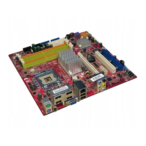
- Page 1 Q35MDO/G33MDH/Q33M MS-7358 ( V1.X ) Mainboard...
-
Page 2: Trademarks
Alternatively, please try the following help resources for further guidance. Visit the MSI website for FAQ, technical guide, BIOS updates, driver updates, an d ot h er i n f orm at i on: h t t p: / / g l o ba l . -
Page 3: Safety Instructions
Safety Instructions Always read the safety instructions carefully. Keep this User’s Manual for future reference. Keep this equipment away from humidity. Lay this equipment on a reliable flat surface before setting it up. The openings on the enclosure are for air convection hence protects the equip- ment from overheating. -
Page 4: Fcc-B Radio Frequency Interference Statement
VOIR LA NOTICE D’INSTALLATION AVANT DE RACCORDER AU RESEAU. Micro-Star International MS-7358 This device complies with Part 15 of the FCC Rules. Operation is subject to the following two conditions: (1) this device may not cause harmful interference, and (2) this device must accept any interference received, including interference that may cause undesired operation. -
Page 5: Weee (Waste Electrical And Electronic Equipment) Statement
WEEE (Waste Electrical and Electronic Equipment) Statement... -
Page 8: Table Of Contents
CONTENTS Copyright Notice ......................ii Trademarks ........................ii Revision History ......................ii Technical Support ......................ii Safety Instructions ......................iii FCC-B Radio Frequency Interference Statement ............iv W EEE (Waste Electrical and Electronic Equipment) Statement ........v Chapter 1. Getting Started ..................1-1 Mainboard Specifications ................... - Page 9 Appendix B. Dual Core Center ................B-1 Activating Dual Core Center ................B-2 Main ........................B-3 DOT (Dynamic OverClocking) ................B-5 Clock ........................B-6 Voltage ......................... B-7 FAN Speed ......................B-8 Temperature ......................B-9 User Profile ......................B-10 Appendix C Intel ICH9R/ICH9DO SATA RAID ............C-1 Introduction ......................
-
Page 10: Chapter 1. Getting Started
Getting Started Chapter 1 Getting Started Thank you for choosing the Q35MDO / G33MDH / Q33M Series (MS-7358 v1.X) ATX mainboard. The Q35MDO / G33MDH / Q33M Series mainboards are based on Intel ® Q35/G33/Q33 & ICH9R/ICH9DO/ICH9DH chipsets for op- timal system efficiency. -
Page 11: Mainboard Specifications
- Supports EIST Technology - Supports Hyper-Threading (HT) Technology - Supports Intel Dual Core Technology up to 1333 MHz (For the latest information about CPU, please visit http://global. msi.com.tw/index.php?func=cpuform) Supported FSB - 1333/ 1066/ 800 MHz Chipset - North Bridge: Intel Q33/Q35/G33 chipset ®... -
Page 12: Getting Started
Getting Started TPM (optional) - Supports TPM by INFINEON SLB9635TT12 Floppy - 1 floppy port - Supports 1 FDD with 360KB, 720KB, 1.2MB, 1.44MB and 2.88MB Connectors Back panel - 1 PS/2 mouse port - 1 PS/2 keyboard port - 1 VGA port - 2 e-SATA ports - 6 USB 2.0 Ports - 1 LAN jack (10/100/1000) -
Page 13: Mainboard Layout
PCI_ E1 LAN CHIP BATT JCASE1 JSPI1 PCI 1 Intel ICH9R/ ICH9DO/ ICH9DH PCI 2 VT6308P Codec (optional) JBAT1 J1394_1 JSPD1 JU SB3 JAUD1 CD_IN1 JUSB1 JU SB2 (optional) JFP1 JFP2 Q35MDO / G33MDH / Q33M Series (MS-7358 v1.X) ATX Mainboard... -
Page 14: Packing Checklist
Getting Started Packing Checklist MSI Driver/Utility CD SATA Cable (Optional) MSI motherboard Standard Cable for Power Cable Back IO Shield IDE Devices User’s Guide 1394 Bracket (Optional) USB Bracket (Optional) * The pictures are for reference only and may vary from the packing... -
Page 15: Chapter 2. Hardware Setup
Hardware Setup Chapter 2 Hardware Setup This chapter provides you with the information about hardware setup procedures. While doing the installation, be careful in holding the components and follow the installation procedures. For some components, if you install in the wrong orientation, the components will not work properly. -
Page 16: Quick Components Guide
M S-7358 M ainboard Quick Components Guide JPW1, CPU, CPUFAN1, DIMM, JCOM1, p.2-9 p.2-3 p.2-14 p.2-7 p.2-17 FDD1, p.2-12 Back Panel, p.2-10 IDE1, p.2-12 JPWR3, p.2-9 PCI_E, p.2-20 SYSFAN1, p.2-14 PCI, SATA1~5, p.2-20 p.2-13 JSPD1, J1394_1, JUSB1~3, JFP1, JFP2, p.2-15 p.2-15 p.2-18 p.2-16... -
Page 17: Cpu (Central Processing Unit)
W hen you are installing the CPU, make sure to install the cooler to prevent overheating. If you do not have the CPU cooler, consult your dealer before turning on the computer. For the latest information about CPU, please visit http://global.msi.com.tw/index.php? func=cpuform Important Overheating Overheating will seriously damage the CPU and system. -
Page 18: Cpu & Cooler Installation
M S-7358 M ainboard CPU & Cooler Installation W hen you are installing the CPU, make sure the CPU has a cooler attached on the top to prevent overheating. Meanwhile, do not forget to apply some thermal paste on CPU before installing the heat sink/cooler fan for better heat dispersion. Follow the steps below to install the CPU &... - Page 19 Hardware Setup 5. Lift the load lever up and open the 6. After confirming the CPU direction load plate. for correct mating, put down the CPU in the socket housing frame. Be sure to grasp on the edge of the CPU base. Note that the align- ment keys are matched.
- Page 20 M S-7358 M ainboard 9. Press down the load lever lightly 10. Align the holes on the mainboard onto the load plate, and then se- with the heatsink. Push down the cure the lever with the hook under c ooler u nti l i ts f ou r c lip s g et retention tab.
-
Page 21: Memory
Hardware Setup Memory These DIMM slots are used for installing memory modules. For more information on compatible components, please visit http://global.msi.com. tw/index.php?func=testreport DDR2 240-pin, 1.8V 64x2=128 pin 56x2=112 pin Single-Channel: All DIMMs in GREEN Dual-Channel: Channel A in GREEN; Channel B in ORANGE... -
Page 22: Installing Memory Modules
M S-7358 M ainboard Installing Memory Modules 1. The memory module has only one notch on the center and will only fit in the right orientation. 2. Insert the memory module vertically into the DIMM slot. Then push it in until the golden finger on the memory module is deeply inserted in the DIMM slot. -
Page 23: Power Supply
Hardware Setup Power Supply ATX 24-Pin Power Connector: JPWR3 pin 13 This connector allows you to connect an ATX 24-pin power supply. To connect the ATX 24-pin power supply, make sure the plug of the power supply is inserted in the proper orientation and the pins are aligned. -
Page 24: Back Panel
M S-7358 M ainboard Back Panel USB Ports RS-Out L-In M ou se eSATA Port CS-Out Keyboard L-Out 1394 Port VGA Port USB Ports SS-Out (optional) M ouse/Keyboard The standard PS/2 mouse/keyboard DIN connector is for a PS/2 mouse/keyboard. ® ®... - Page 25 Hardware Setup Audio Ports These audio connectors are used for audio devices. You can differentiate the color of the audio jacks for different audio sound effects. Line-In (Blue) - Line In is used for external CD player, tapeplayer or other audio devices. Line-Out (Green) - Line Out, is a connector for speakers or headphones.
-
Page 26: Connectors
M S-7358 M ainboard Connectors Floppy Disk Drive Connector: FDD1 This connector supports 360KB, 720KB, 1.2MB, 1.44MB or 2.88MB floppy disk drive. FDD1 IDE Connector: IDE1 This connector supports IDE hard disk drives, optical disk drives and other IDE devices. IDE1 Important If you install two IDE devices on the same cable, you must configure the... - Page 27 Hardware Setup Serial ATA Connector: SATA1 ~ SATA5 This connector is a high-speed Serial ATA interface port. Each connector can connect to one Serial ATA device. SATA1 SATA2 SATA2 supported by Marvell 88SE6111 SATA3 SATA5 SATA4 SATA1,3,4,5 supported by ICH9R/ICH9DO/ICH9DH Important Please do not fold the Serial ATA cable into 90-degree angle.
- Page 28 M S-7358 M ainboard Fan Power Connectors: CPUFAN1, SYSFAN1 The fan power connectors support system cooling fan with +12V. W hen connecting the wire to the connectors, always note that the red wire is the positive and should be connected to the +12V; the black wire is Ground and should be connected to GND. If the mainboard has a System Hardware Monitor chipset on-board, you must use a specially designed fan with speed sensor to take advantage of the CPU fan control.
- Page 29 Hardware Setup IEEE1394 Connector: J1394_1(optional) This connector allows you to connect the IEEE1394 device via an optional IEEE1394 bracket. Pin Definition SIGNAL SIGNAL TPA+ TPA- Ground Ground J1394_1 TPB+ TPB- Cable power Cable power Key (no pin) Ground IEEE1394 Bracket (Optional) S/PDIF-Out Connector: JSPD1 This connector is used to connect S/PDIF (Sony &...
-
Page 30: Front Panel Connectors: Jfp1, Jfp2
M S-7358 M ainboard Front Panel Connectors: JFP1, JFP2 These connectors are for electrical connection to the front panel switches and LEDs. The JFP1 is compliant with Intel ® Front Panel I/O Connectivity Design Guide. Power Power Speaker Switch JFP2 JFP1 Power Reset... - Page 31 Hardware Setup Front Panel Audio Connector: JAUD1 This connector allows you to connect the front panel audio and is compliant with Intel ® Front Panel I/O Connectivity Design Guide. JAUD1 HD Audio Pin Definition SIGNAL DESCRIPTION MIC_L Microphone - Left channel Ground MIC_R Microphone - Right channel...
- Page 32 M S-7358 M ainboard Front USB Connector: JUSB1 ~ 3 These connectors, compliant with Intel ® I/O Connectivity Design Guide, is ideal for connecting high-speed USB interface peripherals such as USB HDD, digital cameras, M P3 players, printers, modems and the like. Pin Definition SIGNAL SIGNAL...
-
Page 33: Jumpers
Hardware Setup Jumper Clear CMOS Jumper: JBAT1 There is a CMOS RAM onboard that has a power supply from an external battery to keep the data of system configuration. W ith the CMOS RAM, the system can auto- matically boot OS every time it is turned on. If you want to clear the system configuration, set the jumper to clear data. -
Page 34: Slots
M S-7358 M ainboard Slots PCI (Peripheral Component Interconnect) Express Slot The PCI Express slot supports the PCI Express interface expansion card. The PCI Express x 16 slot supports up to 4.0 GB/s transfer rate. The PCI Express x 1 slot supports up to 250 MB/s transfer rate. PCI Express x16 Slot PCI Express x1 Slot PCI (Peripheral Component Interconnect) Slot... -
Page 35: Pci Interrupt Request Routing
Hardware Setup PCI Interrupt Request Routing The IRQ, acronym of interrupt request line and pronounced I-R-Q, are hardware lines over which devices can send interrupt signals to the microprocessor. The PCI IRQ pins are typically connected to the PCI bus pins as follows: Order 1 Order 2 Order 3... -
Page 36: Chapter 3. Bios Setup
BIOS Setup Chapter 3 BIOS Setup This chapter provides information on the BIOS Setup program and allows you to configure the system for optimum use. You may need to run the Setup program when: ² An error message appears on the screen during the system booting up, and requests you to run SETUP. -
Page 37: Entering Setup
M S-7358 M ainboard Entering Setup Power on the computer and the system will start POST (Power On Self Test) process. W hen the message below appears on the screen, press <DEL> key to enter Setup. Press DEL to enter SETUP If the message disappears before you respond and you still wish to enter Setup, restart the system by turning it OFF and On or pressing the RESET button. -
Page 38: Control Keys
BIOS Setup Control Keys < ↑> Move to the previous item < ↓> Move to the next item < ←> Move to the item in the left hand < →> Move to the item in the right hand <Enter> Select the item <Esc>... -
Page 39: The Main Menu
M S-7358 M ainboard The Main Menu Standard CM OS Features Use this menu for basic system configurations, such as time, date etc. Advanced BIOS Features Use this menu to setup the items of AMI ® special enhanced features. Integrated Peripherals Use this menu to specify your settings for integrated peripherals. - Page 40 BIOS Setup Load Optimized Defaults Use this menu to load the default values set by the mainboard manufacturer specifi- cally for optimal performance of the mainboard. BIOS Setting Password Use this menu to set the password for BIOS. Save & Exit Setup Save changes to CMOS and exit setup.
-
Page 41: Standard Cmos Features
M S-7358 M ainboard Standard CMOS Features The items in Standard CMOS Features Menu includes some basic setup items. Use the arrow keys to highlight the item and then use the <PgUp> or <PgDn> keys to select the value you want in each item. Date (MM:DD:YY) This allows you to set the system to the date that you want (usually the current date). - Page 42 BIOS Setup Device / Vender / Size It will showing the device information that you connected to the SATA connector. LBA/Large M ode This allows you to enable or disable the LBA Mode. Setting to Auto enables LBA mode if the device supports it and the devices is not already formatted with LBA mode disabled.
- Page 43 M S-7358 M ainboard System Information Press <Enter> to enter the sub-menu, and the following screen appears. This sub-menu shows the CPU information, BIOS version and memory status of your system (read only).
-
Page 44: Advanced Bios Features
BIOS Setup Advanced BIOS Features Full Screen LOGO Display This item enables you to show the company logo on the bootup screen. Settings are: [Enabled] Shows a still image (logo) on the full screen at boot. [Disabled] Shows the POST messages at boot. Quick Booting Setting the item to [Enabled] allows the system to boot within 10 seconds since it will skip some check items. - Page 45 M S-7358 M ainboard MPS Table Version This field allows you to select which MPS (Multi-Processor Specification) version to be used for the operating system. You need to select the MPS version supported by your operating system. To find out which version to use, consult the vendor of your operating system.
- Page 46 BIOS Setup HPET The HPET (High Precision Event Timers) is a component that is part of the chipset. You can to enable it, and will provide you with the means to get to it via the various ACPI methods. VGA Share Memory Size The system shares memory to the onboard VGA card.
-
Page 47: Integrated Peripherals
M S-7358 M ainboard Integrated Peripherals USB Controller This setting allows you to enable/disable the onboard USB controller. USB Device Legacy Support Select [Enabled] if you need to use a USB-interfaced device in the operating system. Onboard LAN Controller This item is used to enable/disable the onboard LAN controller. LAN Option ROM This item is used to decide whether to invoke the Boot ROM of the LAN controller. - Page 48 BIOS Setup PCI IDE BusMaster This item allows you to enable/ disable BIOS to used PCI busmastering for reading/ writing to IDE drives. Oc-Chip SATA Controller These items allow users to enable or disable the SATA controller. RAID M ode This item is used to enable/disable the RAID function for SATA devices.
-
Page 49: Power Management Setup
M S-7358 M ainboard Power Management Setup Important S3-related functions described in this section are available only when your BIOS supports S3 sleep mode. ACPI Function This item is to activate the ACPI (Advanced Configuration and Power Management Interface) Function. If your operating system is ACPI-aware, such as W indows 2000/ XP, select [Enabled]. - Page 50 BIOS Setup Re-Call VGA BIOS From S3 W hen ACPI Standby State is set to [S3], users can select the options in this field. Selecting [Yes] allows BIOS to call VGABIOS to initialize the VGA card when system wakes up (resumes) from S3 sleep state. The system resume time is shortened when you disable the function, but system will need an VGA driver to initialize the VGA card.
- Page 51 M S-7358 M ainboard Resume From S3 By PS/2 M ouse This setting determines whether the system will be awakened from what power saving modes when input signal of the PS/2 mouse is detected. Resume From S3 By Onboard LAN This setting determines whether the system will be awakened from what power saving modes when input signal of the onboard LAN is detected.
-
Page 52: Pnp/Pci Configurations
BIOS Setup PNP/PCI Configurations This section describes configuring the PCI bus system and PnP (Plug & Play) feature. PCI, or Peripheral Component Interconnect, is a system which allows I/O devices to operate at speeds nearing the speed the CPU itself uses when communicating with its special components. - Page 53 M S-7358 M ainboard IRQ Resource Setup Press <Enter> to enter the sub-menu and the following screen appears. IRQ 3/4/5/7/9/10/11/14/15 These items specify the bus where the specified IRQ line is used. The settings determine if AMIBIOS should remove an IRQ from the pool of avail- able IRQs passed to devices that are configurable by the system BIOS.
-
Page 54: H/W Monitor
BIOS Setup H/W Monitor Chassis Intrusion The field enables or disables the feature of recording the chassis intrusion status and issuing a warning message if the chassis is once opened. To clear the warning message, set the field to [Reset]. The setting of the field will automatically return to [Enabled] later. -
Page 55: Frequency/Voltage Control
M S-7358 M ainboard Frequency/Voltage Control Important Change these settings only if you are familiar with the chipset. Current CPU / DRAM Frequency These items show the current clocks of CPU and Memory speed. Read-only. overclocking steps. These items allow users to select the speed up range of each step. - Page 56 BIOS Setup Disabled for optimal system stability and performance. But if you are plagued by EMI, set to Enabled for EMI reduction. Remember to disable Spread Spectrum if you are overclocking because even a slight jitter can introduce a temporary boost in clock speed which may just cause your overclocked processor to lock up.
-
Page 57: Load Fail-Safe/ Optimized Defaults
M S-7358 M ainboard Load Fail-Safe/ Optimized Defaults The two options on the main menu allow users to restore all of the BIOS settings to the default Fail-Safe or Optimized values. The Optimized Defaults are the default values set by the mainboard manufacturer specifically for optimal performance of the mainboard. -
Page 58: Bios Setting Password
BIOS Setup BIOS Setting Password W hen you select this function, a message as below will appear on the screen: Type the password, up to six characters in length, and press <Enter>. The password typed now will replace any previously set password from CMOS memory. You will be prompted to confirm the password. -
Page 59: Appendix A Realtek Alc888 Audio
Realtek ALC888 Audio Appendix A Realtek ALC888 Audio The Realtek ALC888 provides 10-channel DAC that si- multaneously supports 7.1 sound playback and 2 chan- nels of independent s tereo s ound output (multiple streaming) through the Front-Out-Left and Front-Out- Right channels. -
Page 60: Installing The Realtek Hd Audio Driver
M S-7358 M ainboard Installing the Realtek HD Audio Driver You need to install the driver for Realtek ALC888 codec to function properly before you can get access to 2-, 4-, 6-, 8- channel or 7.1+2 channel audio operations. Follow the procedures described below to install the drivers for different operating systems. - Page 61 Realtek ALC888 Audio 3. Click Next to install the Realtek High Definition Audio Driver. Click here 4. Click Finish to restart the system. S el ec t t hi s option Click here...
-
Page 62: Software Configuration
M S-7358 M ainboard Software Configuration After installing the audio driver, you are able to use the 2-, 4-, 6- or 8- channel audio feature now. Click the audio icon from the system tray at the lower-right corner of the screen to activate the HD Audio Configuration. It is also available to enable the audio driver by clicking the Realtek HD Audio M anager from the Control Panel. -
Page 63: Sound Effect
Realtek ALC888 Audio Sound Effect Here you can select a sound effect you like from the Environment list. Environment Simulation You will be able to enjoy different sound experience by pulling down the arrow, totally 23 kinds of sound effect will be shown for selection. Realtek HD Audio Sound Manager also provides five popular settings “Stone Corridor”, “Bathroom”, “Sewer pipe”, “Arena”... - Page 64 M S-7358 M ainboard Equalizer Selection Equalizer frees users from default settings; users may create their owned preferred settings by utilizing this tool. 10 bands of equalizer, ranging from 100Hz to 16KHz. Save Reset The settings are saved 10 bands of equalizer permanently for future would go back to the de- fault setting...
- Page 65 Realtek ALC888 Audio Frequently Used Equalizer Setting Realtek recognizes the needs that you might have. By leveraging our long experience at audio field, Realtek HD Audio Sound Manager provides you certain optimized equal- izer settings that are frequently used for your quick enjoyment. [How to Use It] Other than the buttons “Pop”...
- Page 66 M S-7358 M ainboard Mixer In the Mixer part, you may adjust the volumes of the rear and front panels individually. 1. Adjust Volume You can adjust the volume of the speakers that you pluged in front or rear panel by select the Realtek HD Audio rear output or Realtek HD Audio front output items.
- Page 67 Realtek ALC888 Audio W hen you are playing the first audio source (for example: use W indows Media Player to play DVD/VCD), the output will be played from the rear panel, which is the default setting. Then you must to select the Realtek HD Audio front output from the scroll list first, and use a different program to play the second audio source (for example: use Winamp to play MP3 files).
-
Page 68: Playback Control
M S-7358 M ainboard 3. Playback control Playback device Tool Mute This function is to let you freely decide which ports to output the sound. And this is essential when multi- streaming playback enabled. - Realtek HD Audio Rear Output - Realtek HD Audio Front Output M u te You may choose to mute single or multiple volume controls or to completely mute... - Page 69 Realtek ALC888 Audio 4. Recording control Recording device Tool Mute -Back Line in/Mic, Front Lin in -Realtek HD Audio Input M u te You may choose to mute single or multiple volume controls or to completely mute sound input. Tool - Show the following volume controls This is to let you freely decide which volume control items to be displayed.
- Page 70 M S-7358 M ainboard Audio I/O In this tab, you can easily configure your multi-channel audio function and speakers. You can choose a desired multi-channel operation here. a. Headphone for the common headphone b. 2CH Speaker for Stereo-Speaker Output c. 4CH Speaker for 4-Speaker Output d.
- Page 71 Realtek ALC888 Audio Connector Settings Click to access connector settings. Disable front panel jack detection (option) Find no function on front panel jacks? Please check if front jacks on your system are so-called AC’97 jacks. If so, please check this item to disable front panel jack detection. M ute rear panel output when front headphone plugged in.
- Page 72 M S-7358 M ainboard S/PDIF Short for Sony/Philips Digital Interface, a standard audio file transfer format. S/PDIF allows the transfer of digital audio signals from one device to another without having to be converted first to an analog format. Maintaining the viability of a digital signal prevents the quality of the signal from degrading when it is converted to analog.
- Page 73 Realtek ALC888 Audio Test Speakers You can select the speaker by clicking it to test its functionality. The one you select will light up and make testing sound. If any speaker fails to make sound, then check whether the cable is inserted firmly to the connector or replace the bad speakers with good ones.
- Page 74 M S-7358 M ainboard Microphone In this tab you may set the function of the microphone. Select the Noise Suppres- sion to remove the possible noise during recording, or select Acoustic Echo Can- cellation to cancel the acoustic echo druing recording. Acoustic Echo Cancellation prevents playback sound from being recorded by microphone together with your sound.
-
Page 75: D Audio Demo
Realtek ALC888 Audio 3D Audio Demo In this tab you may adjust your 3D positional audio before playing 3D audio applica- tions like gaming. You may also select different environment to choose the most suitable environment you like. A-17... - Page 76 M S-7358 M ainboard Information In this tab it provides some information about this HD Audio Configuration utility, including Audio Driver Version, DirectX Version, Audio Controller & Audio Codec. You may also select the language of this utility by choosing from the Language list. Also there is a selection Show icon in system tray.
-
Page 77: Hardware Setup
Realtek ALC888 Audio Hardware Setup Connecting the Speakers W hen you have set the Multi-Channel Audio Function mode properly in the software utility, connect your speakers to the correct phone jacks in accordance with the setting in software utility. n 2-Channel M ode for Stereo-Speaker Output Refer to the following diagram and caption for the function of each phone jack on the back panel when 2-Channel Mode is selected. - Page 78 M S-7358 M ainboard n 4-Channel M ode for 4-Speaker Output 4-Channel Analog Audio Output Line In Line Out (Front channels) Line Out (Rear channels) No function No function A-20...
- Page 79 Realtek ALC888 Audio n 6-Channel M ode for 6-Speaker Output 6-Channel Analog Audio Output Line In Line Out (Front channels) Line Out (Rear channels) Line Out (Center and Subwoofer channel) No function A-21...
- Page 80 M S-7358 M ainboard n 8-Channel M ode for 8-Speaker Output 8-Channel Analog Audio Output Line In Line Out (Front channels) Line Out (Rear channels) Line Out (Center and Subwoofer channel) Line Out (Side channels) Important To enable 7.1 channel audio-out function on Vista operating system, you have to install the Realtek Audio Driver.
-
Page 81: Appendix B Dual Core Center
Dual Core Center Dual CoreCenter, the most useful and powerful utility that MSI has spent muc h researc h and ef forts to develop, helps users to monitor or configure the hard- ware status of MSI Mainboard & MSI Graphics card in windows, such as CPU/GPU clock, voltage, fan speed and temperature. -
Page 82: Activating Dual Core Center
Activating Dual Core Center Once you have your Dual Core Center installed (locate the setup source file in the setup CD accompanying with your mainboard, path: Utility --> MSI Utility --> Dual Core Center), it will have an icon in the system tray, a short cut icon on the desktop, and a short cut path in your “Start-up”... -
Page 83: Main
Dual Core Center Main Before using this utility, we have to remind you: only when installing the MSI V044 (V044 has to install with the version 8.26 or newer driver)/ V046 or V060 graphics card can activate the full function of this utility. If you install a graphics card of other brand, only hardware status of the MSI mainboard would be available. - Page 84 M S-7358 M ainboard AV/ Game/ Office/ Silence/ Cool MSI provides five common settings for different environments. The settings had been set to optimal values to reac h better performanc e in eac h environment. Click the button you need.
-
Page 85: Dot (Dynamic Overclocking
Dual Core Center DOT (Dynamic OverClocking) Dynamic Overclocking Technology is an automatic overclocking function, included in the MSI ’s newly developed Dual CoreCenter Technology. It is designed to detect the loading of CPU/ GPU while running programs, and to over-clock automatically. When... -
Page 86: Clock
M S-7358 M ainboard Clock In the Clock sub-menu, you can see clock status (including FSB/ CPU clock of mainboard and GPU/ memory clock of graphics card) of your system. And you can select desired value for overclocking. There will be several items for you to select for overclocking after you click button. -
Page 87: Voltage
Dual Core Center Voltage In the Voltage sub-menu, you can see voltage status (including Vcore, memory, GPU voltage... etc.) of your system, and you can select desired value for overclocking. It will show several items to select for overclocking after you click the button. -
Page 88: Fan Speed
M S-7358 M ainboard FAN Speed In the FAN Speed sub-menu, you can read fan status of your system. Select higher speed for better cooling effect. There are several sections for you to change the fan speed to a section after clicking button. -
Page 89: Temperature
Dual Core Center Temperature In the Temperature sub-menu, you can see temperature status of your system. On the underside, it shows the graphs of the temperatures. Only the curves of the item which the button is lit up with red color will be shown. -
Page 90: User Profile
M S-7358 M ainboard User Profile In the User Profile sub-menu, click the setting button that besides the user profile bar, and the next screen will appear. Here you can define the clock/ fan speed/ voltage by your need, click the button to choose a value quickly, or click the plus / minus sign button to... - Page 91 Dual Core Center Use the draw bar to set the max system temperature. W hen the system temperature exceeds the threshold you defined, the system will pop up a warning message and shut down the system. Use the draw bar to set the minimal fan speed. When the fan speed is lower than the threshold you defined, the system will pop up a warning message.
-
Page 92: Appendix C Intel Ich9R/Ich9Do Sata Raid
Intel ICH9R/ICH9DO SATA RAID Appendix C Intel ICH9R / ICH9DO SATA RAID This appendix will assist users in configuring and en- abling RAID functionality on platforms The ICH9R / ICH9DO RAID solution supports RAID level 0 (striping), RAID level 1 (mirroring), RAID level 5 (striping with parity) and RAID level 10 (striping and mirroring). -
Page 93: Introduction
M S-7358 M ainboard Introduction The ICH9R / ICH9DO provides a hybrid solution that combines 6 independent SATAII ports for support of up to 6 Serial ATAII (Serial ATAII RAID) drives. Serial ATAII (SATAII) is the latest generation of the ATA interface. SATA hard drives deliver blistering transfer speeds up to 300MB/sec. -
Page 94: Bios Configuration
Intel ICH9R/ICH9DO SATA RAID BIOS Configuration The Intel Matrix Storage Manager Option ROM should be integrated with the system BIOS on all motherboards with a supported Intel chipset. The Intel Matrix Stroage Manager Option ROM is the Intel RAID implementation and provides BIOS and DOS disk services. - Page 95 M S-7358 M ainboard After pressing the <Ctrl> and <I> keys simultaneously, the following window will appear: (1) Create RAID Volume Select option 1 “Create RAID Volume” and press <Enter> key. The following screen appears. Then in the Name field, specify a RAID Volume name and then press the <TAB>...
- Page 96 Intel ICH9R/ICH9DO SATA RAID In the Disk field, press <Enter> key and the following screen appears. Use <Space> key to select the disks you want to create for the RAID volume, then click <Enter> key to finish selection. Then select the strip value for the RAID array by using the “upper arrow” or “down arrow”...
- Page 97 M S-7358 M ainboard Important Since you want to create two volumes (Intel Matrix RAID Technology), this default size (maximum) needs to be reduced. Type in a new size for the first volume. As an example: if you want the first volume to span the first half of the two disks, re-type the size to be half of what is shown by default.
- Page 98 Intel ICH9R/ICH9DO SATA RAID (2) Delete RAID Volume Here you can delete the RAID volume, but please be noted that all data on RAID drives will be lost. Important If your system currently boots to RAID and you delete the RAID volume in the Intel RAID Option ROM, your system will become unbootable.
- Page 99 M S-7358 M ainboard (3) Reset Disks to Non-RAID Select option 3 Reset Disks to Non-RAID and press <Enter> to delete the RAID volume and remove any RAID structures from the drives. The following screen appears: Press <Y> key to accept the selection. Important 1.
-
Page 100: Installing Driver
Please follow the instruction below to make an “Intel RAID Driver” for ® yourself. 1. Insert the MSI CD into the CD-ROM drive. 2. Click the “Browse CD” on the Setup screen. 3. Copy all the contents in \\IDE\Intel\ICH9R\Floppy to a formatted floppy diskette. - Page 101 M S-7358 M ainboard † Existing Windows Vista/XP/2000 Driver Installation 1. Insert the MSI CD into the CD-ROM drive. 2. The CD will auto-run and the setup screen will appear. 3. Under the Driver tab, click on Intel IAA RAID Edition.
-
Page 102: Installing Software
For this reason, you cannot remove or un-install this driver from the system after installation; however, you will have the ability to un-install all other non-driver components. Insert the MSI CD and click on the Intel IAA RAID Editor to install the software. Click on this item C-11... - Page 103 M S-7358 M ainboard The InstallShield Wizard will begin automatically for installation showed as following: Click on the Next button to proceed the installation in the welcoming window. C-12...
- Page 104 Intel ICH9R/ICH9DO SATA RAID The window shows the components to be installed. Click Next button to continue. After reading the license agreement in the following window, click Yes button to continue. C-13...
- Page 105 M S-7358 M ainboard The following window appears to show the Readme File Information. It shows the system requirements and installation information. Once the installation is complete, the following window appears. C-14...
-
Page 106: Raid Migration Instructions
Intel ICH9R/ICH9DO SATA RAID RAID Migration Instructions The Intel Matrix Storage Console offers the flexibility to upgrade from a single Serial ATA (SATA) hard drive to RAID configuration when an additional SATA hard drive is added to the system. This process will create a new RAID volume from an existing disk. -
Page 107: Create Raid Volume From Existing Disk
M S-7358 M ainboard Create RAID Volume from Existing Disk To create a RAID volume from an existing disk, choose Action --> Create RAID Volume from Existing Hard Drive. The Create RAID Volume from Existing Hard Drive Wizard pops up to lead you for the following procedure. - Page 108 Intel ICH9R/ICH9DO SATA RAID (1) Step 1: Configure Volume Here you can configure the new RAID volume by entering the volume name, selecting the RAID level and strip size. † RAID Volume Name: A desired RAID volume name needs to be typed in where the ‘RAID_Volume1’ text currently appears above.
- Page 109 M S-7358 M ainboard expensive (requiring read-in prior to write, in order to be able to calculate the correct parity information), or similar to RAID-1 writes. The write efficiency depends heavily on the amount of memory in the machine, and the usage pattern of the array.
- Page 110 Intel ICH9R/ICH9DO SATA RAID (3) Select Member Hard Drive(s) Then select the member disk (the target disk) that you wish to use and then click “- -->” to move it to the Selected field. Then click Next to continue. Please note that the existing data on the selected hard drive(s) will be deleted permanently.
- Page 111 M S-7358 M ainboard (4) Specify Volume Size Specify the amount of available array space to be used by the new RAID volume. You may enter the amount in the space or use the slider to specify. It is recommended you use 100% of the available space for the optimized usage.
- Page 112 Intel ICH9R/ICH9DO SATA RAID (6) Start Migration The migration process may take up to two hours to complete depending on the size of the disks being used and the strip size selected. A dialogue window will appear stating that the migration process may take considerable time to complete, meanwhile a popup dialogue at the taskbar will also show the migration status.
-
Page 113: Degraded Raid Array
M S-7358 M ainboard Degraded RAID Array A RAID 1, RAID 5 or RAID 10 volume is reported as degraded when one of its hard drive members fails or is temporarily disconnected, and data mirroring is lost. As a result, the system can only utilize theremaining functional hard drive member. To re- establish data mirroring and restore data redundancy, refer to the procedure below that corresponds to the current situation. - Page 114 Intel ICH9R/ICH9DO SATA RAID 5. Exit Intel RAID Option ROM, and then reboot to W indows system. 6. W hen prompted to rebuild the RAID volume, click 'Yes'. 7. The Intel(R) Storage Utility will be launched. Right-click the new hard drive and select 'Rebuild to this Disk'.
Need help?
Do you have a question about the MS-7358 and is the answer not in the manual?
Questions and answers